Table of Contents
Advertisement
Advertisement
Table of Contents

Subscribe to Our Youtube Channel
Related Manuals for Mindray CAL 8000


Summary of Contents for Mindray CAL 8000
- Page 1 CAL 8000 Auto Sample Processing System Operator’s Manual...
- Page 3 Contents of this manual are subject to changes without prior notice. All information contained in this manual is believed to be correct. Mindray shall not be liable for errors contained herein nor for incidental or consequential damages in connection with the furnishing, performance, or use of this manual.
- Page 4 It is important for the hospital or organization that employs this equipment to carry out a reasonable service/maintenance plan. Neglect of this may result in machine breakdown or injury of human health. Be sure to operate the system under the situation specified in this manual; otherwise, the system will not work normally and the analysis results will be unreliable, which would damage the system components and cause personal injury.
- Page 5 FITNESS FOR ANY PARTICULAR PURPOSE. Exemptions Mindray's obligation or liability under this warranty does not include any transportation or other charges or liability for direct, indirect or consequential damages or delay resulting from the improper use or application of the product or the use of parts or accessories not approved by Mindray or repairs by people other than Mindray authorized personnel.
- Page 6 Customer Service Department Manufacturer: Shenzhen Mindray Bio-Medical Electronics Co., Ltd. Mindray Building, Keji 12th Road South, High-tech industrial park, Nanshan, Address: Shenzhen 518057,P.R.China Website: www.mindray.com service@mindray.com E-mail Address: Tel: +86 755 81888998 Fax: +86 755 26582680 EC-Representative: Shanghai International Holding Corp. GmbH(Europe) Eiffestraβe 80, Hamburg 20537, Germany...
-
Page 7: Table Of Contents
Who Should Read This Manual ................1-2 How to Find Information ..................1-3 Safety Information ....................1-4 Symbols ......................... 1-7 Understanding the CAL 8000 System ..............2-1 Introduction ......................2-1 System Configuration .................... 2-2 Assemblies and Modules ..................2-3 2.3.1 Loading Module .................. - Page 8 Table of Contents Reviewing and Processing Sample Results ............. 7-1 Servicing Your System ..................8-1 Introduction ......................8-1 Cleaning......................... 8-2 Replacing ....................... 8-3 Troubleshooting ....................9-1 Introduction ......................9-1 Error Information and Handling ................9-2 Data Managing Unit (DMU) ................10-1 10.1 Overview ......................
- Page 9 Table of Contents B.14.3 USB Flash Disk ................... B-7 Index ........................C-1...
-
Page 11: Using This Manual
This chapter explains how to use your Operator's Manual of CAL 8000 Auto Sample Processing System (hereby referred to as CAL 8000), which is shipped with your CAL 8000 Auto Sample Processing System and contains reference information about CAL 8000 and procedures for operating, troubleshooting and maintaining the system. -
Page 12: Who Should Read This Manual
Using This Manual 1.2 Who Should Read This Manual This manual is intended to be read by clinical laboratory professionals to: learn about the CAL 8000 hardware and software. perform daily operating tasks. perform system maintenance and troubleshooting. -
Page 13: How To Find Information
Sample Results learn about how to service the CAL 8000 8 Servicing Your System learn about how to solve the problems of the CAL 8000 9 Troubleshooting learn about new functions of the DMU after the analyzer is 10 Data Managing Unit (DMU) -
Page 14: Safety Information
Using This Manual 1.4 Safety Information The following symbols are used to indicate danger and alert information in this manual. When you see… Meaning read the statement below the symbol. The statement is alerting you to a potentially biohazardous condition. read the statement below the symbol. - Page 15 Using This Manual 1.4.2 Protection from Other Hazards WARNING If any abnormal smell or fog are observed, power off the system and disconnect the power plug immediately, or else fire, electric shock or other hazards may occur. Do not touch the power cords inside the system, and make sure your hands are dry when operating the system to avoid electric shock.
- Page 16 If the system stop running due to errors, the operator may deal with the errors as instructed by the Operator's Manual; in case of errors not specified in the manual, contact Mindray customer service department. Please use the system strictly as instructed by this manual.
-
Page 17: Symbols
Using This Manual 1.5 Symbols You will find the following symbols in this manual: When you see… Meaning read the statement below the symbol. The statement is alerting you to a potentially biohazardous condition. read the statement below the symbol. The statement is WARNING alerting you to an operating hazard that can cause personnel injury. - Page 18 Using This Manual DATE OF MANUFACTURE MANUFACTURER TEMPERATURE LIMITATION HUMIDITY LIMITATION ATMOSPHERIC PRESSURE LIMITATION THE FOLLOWING DEFINITION OF THE WEEE LABEL APPLIES TO EU MEMBER STATES ONLY: THE USE OF THIS SYMBOL INDICATES THAT THIS PRODUCT SHOULD TREATED HOUSEHOLD WASTE. ENSURING THAT THIS...
- Page 19 Using This Manual Type Label Connotation Location WARNING Power 1. Next to the power inlet of 1. CONNECT ONLY TO Warning the loading unit PROPERLY EARTH 2. Next to the power inlet of GROUNDED OUTLET. the unloading unit AVOID ELECTRIC SHOCK, DISCONNECT 3.
- Page 20 Using This Manual Type Label Connotation Location Transfer To avoid injury, do not put your right track hands between the interior and nonterminal analyzer track movement exterior transfer tracks when the cover, next to the transfer warning system is in operation! track 2.
- Page 21 Using This Manual Type Label Connotation Location Cabinet Be aware for pinching while On the top door rim of each door opening or closing the door! cabinet movement warning 1-11...
- Page 22 Using This Manual Type Label Connotation Location Display To avoid injury, do not put your On the main body of the supporting hand around the joints of the display supporting arm supporting arm while the arm is movement moving! warning 1-12...
- Page 23 Using This Manual Type Label Connotation Location Biological On the top covers of the Warning Hazard loading module, unloading Biological risk module, each track module 1-13...
- Page 24 Using This Manual Type Label Connotation Location Biological Warning On the front cover Hazard Biological risk Vent safety Warning On the side board warning avoid damaging next to the vent Supplementary Reagent Loading Module, do not block the vent at its side.
- Page 25 Using This Manual Connector Caution: Keep the connectors On the side board protection away from collision while next warning transporting the module. reagent connectors CAUTION Make sure the symbols are in good condition during daily use and maintenance. 1-15...
-
Page 27: Understanding The Cal 8000 System
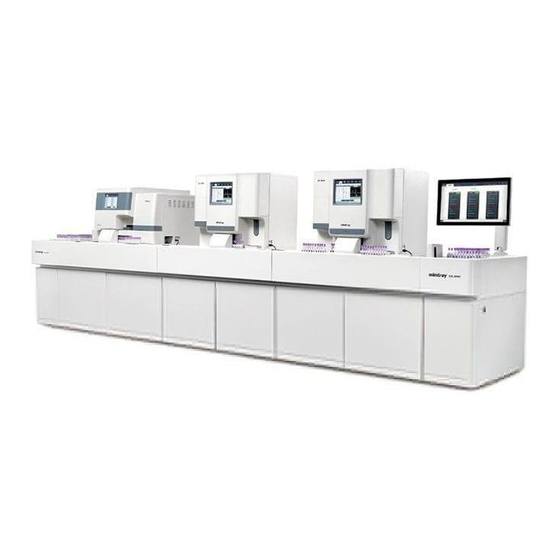
Understanding the CAL 8000 System 2.1 Introduction CAL 8000 Auto Sample Processing System forms a processing line together with Auto Hematology Analyzer (hereby referred to as "Analyzer") and Auto Slide Maker & Stainer (hereby referred to as "SM&S"), which achieves the automatic dispatching, distribution, transport and reclaiming of in-vitro diagnostic samples, and management of the devices connected. -
Page 28: System Configuration
Understanding the CAL 8000 System 2.2 System Configuration The number of track modules in the system is determined by the number of Analyzers and SM&S connected in the auto sample processing line, 6 track modules can be configured at most to transmit and distribute samples for 6 external devices connected. -
Page 29: Assemblies And Modules
Understanding the CAL 8000 System 2.3 Assemblies and Modules CAL 8000 The Auto Sample Processing System mainly includes the loading module, track module (multiple choices of configuration), unloading module, control and management module and accessories. Figure 2-2 Front of the Auto Sample Processing System (configuration: 2+1) - Page 30 Understanding the CAL 8000 System Figure 2-3 Switch and Port in the Front of the Auto Sample Processing System (configuration: 2+1) 1 --- Power Switch of the Auto Sample 2 --- Power Switch of the computer Processing System Power Switch of the Auto Sample Processing System...
-
Page 31: Loading Module
Understanding the CAL 8000 System Figure 2-4 Switches and Ports in the Back of the Auto Sample Processing System (configuration: 2+1) ---Network port computer 2 --- Loading assembly power switch (connecting LIS) 3 ---Network port of the exchanger 4 --- Pneumatic unit control port... - Page 32 Understanding the CAL 8000 System accommodates sample tube racks, reads barcodes of tube racks by barcode scanner and sends the racks to specified track module. Figure 2-5 Loading Module 1 --- Supporting arm assembly 2 --- Display 3 --- Loading assembly...
- Page 33 Understanding the CAL 8000 System Figure 2-6Loading Assembly 1 --- Display unit 2 --- Loading station unit 3 --- Key and indicator unit 4 --- Direction change unit 5 --- Pushing unit 6 --- Barcode scanner unit 7 --- Loading unit ...
- Page 34 Understanding the CAL 8000 System Figure 2-7Key and indicator unit of the loading assembly 1 --- Indicator 2 --- Reset/Mute key 3 --- Push key Ports unit The ports unit consists of station power switch, debug port and network port.
-
Page 35: Track Module
Understanding the CAL 8000 System 2.3.2 Track Module The track module consists of track unit, support track unit and the cabinet. It receives sample racks sent by the loading module, transports them to the analyzer for analysis, or to the SM&S for slide making and staining, and then transports the processed sample racks to the... - Page 36 Understanding the CAL 8000 System Track Module Configuration Nonterminal analyzer track module Figure 2-10 Nonterminal analyzer track module 1 --- Analyzer 2 --- Nonterminal analyzer track assembly 3 --- Cabinet door 4 --- Reagent carriage and reagents 5 ---Waste carriage and waste...
- Page 37 Understanding the CAL 8000 System Nonterminal SM&S track module Figure 2-11 Nonterminal SM&S track module 1 --- SM&S 2 --- Nonterminal SM&S track assembly 3 ---Pneumatic unit carriage and pneumatic 4 --- Cabinet door unit 5 --- Waste carriage and waste...
- Page 38 Understanding the CAL 8000 System Terminal track module Figure 2-12 Terminal Track Module (Analyzer) 1 --- Analyzer 2 --- Terminal track assembly 3 --- Cabinet door Reagent carriage reagent containers 5 --- Waste carriage and waste container 6 --- Pneumatic unit carriage and pneumatic...
- Page 39 Understanding the CAL 8000 System Figure 2-13 Terminal Track Module (SM&S) 1 --- SM&S 2 --- Terminal track assembly 3 ---Pneumatic unit carriage and pneumatic 4 --- Cabinet door unit 5 --- Waste carriage and waste container Reagent carriage reagent...
- Page 40 Understanding the CAL 8000 System Figure 2-14 Left Front View of Nonterminal Track 1 --- Status indicator 2 --- Reset/Mute key 3 --- Unit off-the-line key 4 --- Interior track 5 --- Exterior track Figure 2-15 Left Front View of Terminal Track...
- Page 41 Understanding the CAL 8000 System analyzer or SM&S with sample processing. Figure 2-16 Introduction of the Nonterminal Track 1 --- Anterior transfer track area 2 --- Loading buffer area 3 --- Analyzing area 4 --- Unloading buffer area 5 --- Exterior track waiting area...
-
Page 42: Unloading Module
Understanding the CAL 8000 System 5 --- Exterior track waiting area Figure 2-18 Tube Rack Moving Path of Nonterminal Track Figure 2-19 Tube Rack Moving Path of Terminal Track 2.3.3 Unloading Module The unloading module includes unloading assembly and unloading assembly cabinet. It receives sample tube racks that have been processed from the unloading storage region of the track module, so that users may collect them. - Page 43 Understanding the CAL 8000 System Figure 2-20 Unloading Module 1 --- Unloading assembly 2 --- Exchanger 3 --- Pressure gauge 4 --- Cabinet door The unloading assembly is the exit of the sample processing line, the analyzed tube racks stays here temporarily until you remove them. It can accommodate 20 tube racks at most.
- Page 44 Understanding the CAL 8000 System Figure 2-21 Unloading Assembly 1 --- Unloading station 2 --- Receiving unit 3 --- Unloading unit 4 --- Key and indicator unit Key and indicator unit The key and indicator unit contains two keys and an indicator.
- Page 45 Understanding the CAL 8000 System Figure 2-22 Key and indicator unit of the unloading assembly 1 --- Indicator 2 --- Reset/Mute key 3 --- Manual unloading key Ports unit The ports unit consists of the unloading assembly power switch, pneumatic unit port, debug port and network port.
-
Page 46: Control And Management Module (Cmu)
Understanding the CAL 8000 System Figure 2-23 Ports Unit of the Unloading Assembly 1 --- Network port 2 --- Debug port 3 --- Pneumatic unit control port 4 --- Station power switch 2.3.4 Control and Management Module (CMU) The CMU is the software system integrated in PC. You may run the CMU from an external display to monitor the modules and devices of the sample processing line, track sample flow, set up orders and view samples that have not been analyzed. -
Page 47: System Accessories
Understanding the CAL 8000 System 2.3.5 System Accessories Pneumatic Unit Figure 2-24 Front of the Pneumatic Unit 1 --- Safety valve 2 --- Operation indicator 2-21... - Page 48 Understanding the CAL 8000 System Figure 2-25 Back of the Pneumatic Unit 1 --- Power switch 2 --- Power socket 3 --- Control port 4 --- Vacuum port 5 --- Pressure port Tube Rack See 4.4.1Specifications of Applicable Tubes and Tube Racks for tube rack specifications.
-
Page 49: System Function
Understanding the CAL 8000 System 2.4 System Function 2.4.1 Tube Rack Loading Able to accommodate up to 20 tube racks (200 tubes) with to-be-analyzed samples. 2.4.2 Tube Rack Unloading Able to accommodate up to 20 tube racks (200 tubes) with analyzed samples. - Page 50 Understanding the CAL 8000 System The touch screen is able to move in varied directions, which increases the flexibility of operation by users. 2.4.11 Tube rack Transportation Able to transport tube racks from the loading module to the track module, and then the unloading module.
-
Page 51: Software Interfaces And Operations (Cmu Software)
Tab Area Includes “Instrument Status”, “Sample Tracking”, “Order Setup” and “Log” tabs. Instrument Status This area displays the status of each module of CAL 8000 and each instrument (including reagents) connected to it. Sample flow tracking This area displays the "Sample ID", "Mode", "Time of Analysis", "Position" and whether reexam of the sample is required. - Page 52 Understanding the CAL 8000 System Sample Analysis Area Include the information of “Not analyzed sample(s)”, “Suspect Samples” and “Barcode Unidentified Sample”. Icon Area The title panel displays CMU titles and buttons. Name Icon Function Pause/Continue Pause/Continue the loading Shutdown Shut down the auto sample processing...
- Page 53 Understanding the CAL 8000 System Click the arrow button on the scroll bar. Move the pointer to the slide bar, left click the mouse and hold, then scroll the bar at will. Click the blank area on the scroll bar.
- Page 54 Understanding the CAL 8000 System After modify the settings, click "yes", and the dialog box will be closed with the change saved; click "No", and the dialog box will be closed without saving the change; click “Cancel” to close the dialog box without saving the change, and go back to the previous screen.
-
Page 55: Installing Your System
Installing Your System 3.1 Introduction WARNING Installation by personnel not authorized or trained by Mindray may cause personal injury or damage your system. Do not install your system without the presence of Mindray-authorized personnel. The installation, authorization, upgrade and modification of the system software must be performed by Mindray-authorized personnel. -
Page 56: Installation Requirements
Installing Your System 3.2 Installation Requirements 3.2.1 Space Requirements While installing the system, make sure there is enough space left for service and maintaining operations, as well as for the system to dissipate heat and for the fluidic tubing to be properly placed without extrusion. - Page 57 Installing Your System Nonterminal 100V-240V~ 50/60Hz 100VA SM&S Track Module 100V-240V~ 50/60Hz 100VA Terminal Track Module Compressor a.c. 110V/115V ±10% 60Hz ±2Hz 600VA a.c. 220V/230V ±10% 50Hz ±2Hz 450VA 60Hz ±2Hz 300VA 3.2.3 General Environment Working Storage Operation Environment Environment Environment Ambient 15℃~32℃...
-
Page 58: Moving And Installing The System
Please only use the external PC for sample analysis and the related purposes. Moving and installation of the system shall be conducted by Mindray-authorized personnel. Do not move or install your system without the presence of Mindray-authorized personnel. -
Page 59: Connecting The System
Refer to the Operator's Manual of the analyzer or SM&S for the connections of the device in the sample processing line, its accessories and/or reagents. The connection of each module of the CAL 8000 shall be conducted by Mindray-authorized personnel. -
Page 61: Preparations Before Using
Preparations Before Using 4.1 Introduction This chapter introduces the preparations required before using the CAL 8000, including notes before use, sample preparation, and preparation of tubes and tube racks. -
Page 62: Notes Before Using
Preparations Before Using 4.2 Notes before Using Do not put any heavy object or press heavily on any part of the system to avoid affecting sample transportation or analysis, or distorting any component. Do not disconnect any connection cord to avoid errors. ... -
Page 63: Sample Preparation
Some tubes may not adapt to the tube rack (e.g. tubes with unique caps), in such case, contact Mindray customer service department. Tube Rack To ensure proper running of the system, be sure to use the standard configured tube rack of the CAL 8000. See the following figure for size of the tube rack:... - Page 64 Preparations Before Using 55mm 200mm 25mm Figure 4-2 Size of Tube Rack 4.4.2 Placing Barcodes Before analyzing samples, barcodes must be stuck on sample tubes for sample identification. To ensure good readability of the barcode, you must place the label properly. CAUTION ...
- Page 65 Preparations Before Using below shall be followed: The label shall be stuck properly, as shown in Figure 4-3. Do not stick several labels to one tube. The surface of the label shall not be wrinkled. Do not use barcode label which is easily peeled to prevent the label from peeling.
- Page 66 Preparations Before Using figure. 4.4.4 Preparing Slides and Slide Baskets (SM&S Configured) See the operator’s manual of the slide maker & stainer.
-
Page 67: Operating Your System
Operating Your System 5.1 Introduction This chapter introduces the daily operating process of the CAL 8000 from startup to shutdown. A flow chart presenting the common daily operating process is shown below: Start up the system See 5.3 Startup Run daily QC of the analyzer See Operator’s Manual of the analyzer... -
Page 68: Checks Before Starting The System
Operating Your System 5.2 Checks before Starting the System Perform the following checks before turning on the system. All the samples, controls, calibrators, reagents, wastes and areas contacted them are potentially biohazardous. Wear proper personal protective equipment (e.g. gloves, lab coat, etc.) and follow safe laboratory procedures when handling them and the contacted areas in the laboratory. -
Page 69: Startup
5.3 Startup Start up the system as per the following procedure: Turn on the power switch of the CAL 8000. Open the cabinet door of the loading module, and turn on the power switch of the PC inside the cabinet. -
Page 70: Starting Analysis
Operating Your System 5.4 Starting Analysis Before starting the analysis, check: whether there are clumps in the sample, and whether the sample volume is sufficient for analysis; whether the sample ID barcodes are stuck to the tubes to be analyzed as instructed by 4.4Preparing the Tubes and Tube Racks. -
Page 71: Finishing Analysis
Operating Your System 5.5 Finishing Analysis Close the system as per the following procedure: Exit the SPU software of all analyzers in turn. The procedure is as follows: 1) Tap "Menu">"Shutdown" on the main screen. 2) Tap "Yes" to perform the shutdown procedure; the dialog box will be closed automatically. -
Page 72: Notes During Analysis
Operating Your System 5.6 Notes during Analysis Do not open any cover of the system during analysis to avoid errors. Do not take away tube racks during analysis Do not take away tube racks when they are being transported from the loading tray to the scanning position or when they are on any track module;... -
Page 73: Inserting A Stat Sample
Operating Your System 5.7 Inserting a STAT Sample When a STAT sample needs to be analyzed immediately when the sample processing line is working, you can either analyze it in open-vial using the STAT function of the analyzer, or insert a new tube rack loaded with the STAT sample (see the steps below for details). Place the well prepared STAT sample tube (see the operator’s manual of the analyzer for how to prepare samples) in a tube rack. -
Page 74: Daily Quality Control Of The Analyzers
Operating Your System 5.8 Daily Quality Control of the Analyzers In an auto sample processing line configured with more than one analyzer, the daily quality control of the analyzers can be performed by the way below. Place the well prepared vial of control (see the operator’s manual of the analyzer and instructions for use of the control for how to prepare controls) in a special QC tube rack. -
Page 75: Standby
When all instruments connected by the CAL 8000 are in standby mode, and the system is in idle state for more than 30 minutes, all modules of CAL 8000 will go to the standby mode. To exit standby, place a tube on the loading tray (not applicable when the autoloading function is disabled or the loading module has error), or make any of the instrument in the processing line exit the standby mode (see the operator’s manual of the instrument for how to exit... -
Page 77: Operating The Control And Management Module (Cmu)
This chapter introduces the functions and operations of the CMU module of CAL 8000. -
Page 78: Monitoring System Status
SPS Module Monitor The status of the CAL 8000 modules and instruments are shown by the indicating bars: when the bar is green, the module is working properly; when the bar is red, the module has error(s); when the bar is grey, the module is power-off/not started. - Page 79 Instrument Monitor The status of the CAL 8000 modules and instruments are shown by the indicating bars: when the bar is green, the module is working properly; when the bar is red, the module has error(s);...
- Page 80 Operating the Control and Management Module (CMU) when the bar is grey, the module is power-off/not started. Checking the error information Tap the status monitor area of the module you want to check, and the dialog box below pops up, showing the “Error Info.” and the “IP address” of the module. Tap “Close”...
- Page 81 Operating the Control and Management Module (CMU) Tap on this area and the dialog box below pops up, showing the reagent staus details. Tap “Close” to close the dialog box.
-
Page 82: Monitoring Sample Analysis
Operating the Control and Management Module (CMU) 6.3 Monitoring Sample Analysis 6.3.1 Sample flow tracking In this tab, you can check the current position of a sample, and export the position information of samples in specified period of time. The indications of column heads in the sample flow tracking table are shown as follows: Column Head Indication Sample ID... - Page 83 Operating the Control and Management Module (CMU) Click “Export”, and the dialog below will pop up. Specify the “Date Range”, and the enter or browse to the directory you want to save the exported file. Click “OK” to close the dialog box and start exporting. ...
- Page 84 Operating the Control and Management Module (CMU) Adding a new order You can add a new order as follows: Click "Add", a new line will be added to the order list. Define the "Rack Barcode From" and "To" in the added line, and then set up analysis mode as needed.
- Page 85 Operating the Control and Management Module (CMU) If the switches for both Instrument 1 and 2 are on, the QC tube rack will be transported to both instruments for analysis in turn while running the QC count. 6.3.3 Checking Special Sample Information When the samples are being processed by the auto sample processing system, you may need to check the information of the some special samples.
- Page 86 Operating the Control and Management Module (CMU) Barcode unidentified samples You can check the “Sample ID”, sample “Position”, time and instrument of the analysis, as well test panel. 6.3.4 Checking the Logs The log records the key operations performed on the system. It provides the operators an access to review the operation history and service personnel the facilitation of troubleshooting.
- Page 87 Operating the Control and Management Module (CMU) delete them. Select or enter the starting and ending dates to view the logs in the specified date range. 6-11...
-
Page 89: Reviewing And Processing Sample Results
Reviewing and Processing Sample Results After finishing analysis of a sample, the sample processing line automatically stores results to the sample processing unit (SPU or the main unit) of the analyzer, and transmits the results to the data management unit (DMU) in real-time. Operators may use DMU software to review, report and sort sample results of all analyzers. -
Page 91: Servicing Your System
Improper maintenance may damage the system. Maintenance procedures shall be performed as instructed by this Operator's Manual. In case of problems not specified in this manual, contact Mindray Customer Service Department or Mindray specified professionals for assistance. Only Mindray-supplied parts can be used for maintenance. Should you have any problem, contact Mindray Customer Service Department. -
Page 92: Cleaning
Mindray will not provide any warranty. Mindray does not claim the validity of the listed chemicals in infection control. For effective control of infection, please consult the Infection Prevention Department of the hospital or the epidemic professionals. -
Page 93: Replacing
After replacing the reagent container, check the tubing connected to the cap assembly and make sure it is not bent over. After the instruments are connected into the auto sample processing line by CAL 8000, the reagent containers (except the fluorescent reagents of the analyzer) and the waste containers are placed in the cabinet of the corresponding track module. - Page 94 Replace the waste container or the reagent container as instructed by the operator’s manual of the corresponding instrument. 8.3.3 Replacing the Fuse If the fuse of the system is damaged, contact Mindray Customer Service Department or your local distributor for replacement. WARNING ...
-
Page 95: Troubleshooting
Troubleshooting 9.1 Introduction This chapter contains information that is helpful in locating and correcting problems that may occur during operation of your system. NOTE This chapter is not a complete service manual and is limited to problems that are readily diagnosed and/or corrected by the user of the system. -
Page 96: Error Information And Handling
Troubleshooting 9.2 Error Information and Handling Each of the CAL 8000 loading, unloading and track modules has a reset/mute key. When there is an error with a module, press the reset/mute key of this module for less than 2 seconds to mute the alarm sound; or press and hold the reset/mute key for 2 seconds or more to mute the alarm sound and the system will try removing the error automatically. - Page 97 Troubleshooting 1. Power off the system and restart it after a while. Multiple unloading failed 2. If the error still exists, Contact Mindray Customer Service Department. 1. Power off the system and restart it after a while. Loading mechanism 2. If the error still exists, Contact Mindray Customer operating failed Service Department.
-
Page 99: Data Managing Unit (Dmu)
Data Managing Unit (DMU) 10.1 Overview Compared with the DMU of stand-alone analyzers, the DMU analyzers in the auto sample processing line has some special functions to provide necessary supports for the interaction with the sample processing system and other instruments in the line. This chapter introduces the special functions of the DMU in the auto sample processing line. -
Page 100: Reexam Record
Data Managing Unit (DMU) 10.2 Reexam Record A reexam record is a list of samples which have been used to make slides on the slide maker & stainer. The record contains patient and parameter information for the operator to attain information about the sample in a convenient way. - Page 101 Data Managing Unit (DMU) Select patient information Click the “Select Patient Info.” button, and the dialog below pops up. Select the patient information items you want to be included in the reexam record. Click “OK” to save and exit. ...
-
Page 102: Reexam Record Printing Status
Data Managing Unit (DMU) Select the parameters the result of which you want to be included in the reexam record. Click “OK” to save and exit. 10.2.2 Reexam Record Printing Status In the “Review” and “Report” screens of the DMU for auto sample processing line, there is a “Reexam Record Printing Status”... - Page 103 Data Managing Unit (DMU) Select “Samples with Unprinted Reexam Record of the Day” or “Selected Records” as needed. Click “OK” to exit and start printing. 10-5...
-
Page 104: Acquire Patient Info. From Lis After The Sample Id Editing
Data Managing Unit (DMU) 10.3 Acquire patient info. from LIS after the sample ID Editing For the DMU of the sample processing line, there is a checkbox “Acquire patient info. from LIS after the sample ID is edited”. If this check box is selected, once the patient ID is edited, the system will automatically acquire the patient information from LIS using the new ID. -
Page 105: Serial No. In Lis
Data Managing Unit (DMU) 10.4 Serial No. in LIS For the convenience of the user to match the samples in the DMU to samples in LIS, there is a “Serial No.” column in the “Review” and “Report” screens of the DMU for auto sample processing line. -
Page 106: Sample Traceability
Data Managing Unit (DMU) 10.5 Sample Traceability The sample traceability function enables the users to trace the matching between samples and the information of reagents used for its analysis/corresponding QC information, as well as the matching between the QC results and the reagents used for the analysis. 10.5.1 Tracing the Information of A Certain Sample Click the “View”... -
Page 107: Tracing Samples Corresponding To Specified Batch Of
Data Managing Unit (DMU) Checking the reagent information of selected sample In this tab, you can check the information of the reagents used for the analysis of the selected sample. For open-reagent models, if the user does not input the reagent information after replacing a new container, the information here will be null. -
Page 108: Tracing Reagent Information Used For Control Analysis
Data Managing Unit (DMU) 1) Select the “QC” radio button. 2) Specify the desired “Lot No.” of the control. Click “OK” to close the dialog box, and the software will search for matching samples and display them in the table area. 10.5.3 Tracing Reagent Information Used for Control Analysis In L-J QC Table screen, click “Reagent”, and the dialog box below pops up. -
Page 109: Supplementary Reagent Loading (Srl) Module (Optional)
Supplementary Reagent Loading (SRL) Module (Optional) 11.1 Overview The Supplementary Reagent Loading Module (hereinafter called SRL or SRL module) is an optional module which stores a fixed volume of each reagent. When the error of no reagent is reported, if a SRL module is configured, it will support the analyzer to keep running until the reagent inside the SRL module is used up, during which process the operator need to replace the reagent container. -
Page 110: Structure And Interfaces
Supplementary Reagent Loading (SRL) Module (Optional) 11.2 Structure and Interfaces 1 --- Indicator 2 --- Power switch 3 --- Reserved interface 4 --- Pneumatic unit control interface 5 --- Reagent outlets 6 --- Pneumatic unit interface (vacuum) 7 --- Reagent inlets ... - Page 111 Supplementary Reagent Loading (SRL) Module (Optional) Provide the connection to the pneumatic unit of CAL8000. Reagent inlets Provide the connection to the reagent containers. There are printings showing the corresponding reagent names, and the interfaces are color-coded in the same way as the cable connectors.
-
Page 112: Checking The Pressure Of The Srl Module
Supplementary Reagent Loading (SRL) Module (Optional) 11.3 Checking the Pressure of the SRL Module When the SRL module is configured, tap "Menu" > "Status" > "Temp.&Pressure" to go to the "Temp.&Pressure" screen, where the operator can check the vacuum pressure of "SRL Cistern (VAC)"... -
Page 113: Errors Related To The Srl Module
Supplementary Reagent Loading (SRL) Module (Optional) 11.4 Errors Related to the SRL Module The table below lists the errors might be reported after the SRL module is configured and the corresponding help messages. Error Name Help Message 0x00006029 1. Shut down the analyzer power and SRL module power directly, Serial port and restart them later. -
Page 115: A Glossary
Glossary Control and management module of the Auto Sample Processing System. It monitors the modules and devices of the sample processing line, tracks sample flow, sets up orders and views samples that have not been analyzed. Data management unit of Auto Hematology Analyzer, also called the PC. It runs data management operations, including worklist editing, analysis results reviewing, analysis report generating, and LIS/HIS communication. -
Page 117: Specifications
Specifications B.1 Classification According to the CE classification, the CAL 8000 Auto Processing System belongs to In vitro diagnostic medical devices other than those covered by Annex II. B.2 Ports 2 network ports 1 pneumatic unit control port B.3 Tubes... -
Page 118: Operating Environment
Specifications B.6 Operating Environment Ambient temperature: 15℃~32℃ Optimal operating humidity: 30%~85% Atmospheric pressure: 70kPa~106kPa B.7 Storage Environment Ambient temperature: -10℃~40℃ Relative humidity: 10%~90% Atmospheric pressure: 50kPa~106kPa B.8 Running Environment Ambient temperature: 5℃~40℃ Relative humidity: 10%~90% ... -
Page 119: Contraindication
Specifications Width (mm) Height Depth (mm) Weight (Kg) (mm) ≤1470 ≤1030 8000 (without Varies with Varies with pneumatic unit) specific specific configurations configurations ≤310 ≤480 ≤430 ≤20 Pneumatic Unit ≤1190 ≤880 ≤1030 ≤260 Nonterminal analyzer track module ≤1350 ≤880 ≤1030 ≤350 Nonterminal SM&S... - Page 120 Specifications Not use check digit No more than 20 digits (sample ID) No more than 19 digits (sample ID)+1 digit (check digit) = Use check digit no more than 20 digits Not use check digit No more than 20 digits (sample ID) CODE39 No more than 19 digits (sample ID)+1 digit (check digit) = Use check digit...
- Page 121 Specifications...
-
Page 122: Emc Description
Specifications B.12 EMC Description Do not use this device in close proximity to sources of strong electromagnetic radiation (e.g. unshielded intentional RF sources), as these may interfere with the proper operation. This equipment complies with the emission and immunity requirements of the EN 61326-1:2006 and EN 61326-2-6:2006. -
Page 123: Printer (Optional
Specifications Size: length<465mm, width<190mm, height<25mm B.14.2 Printer (Optional) B.14.3 USB Flash Disk... - Page 125 Index Basic assemblies and modules Operating Your System, 5-1 control and data management module Order Setup, 6-7, 6-10 (CMU), 2-20 Preparation of tubes and tube racks, 4-3 loading module, 2-5 Replacing, 8-3 track module, 2-9 Replacing Reagent Container/Package, unloading module, 2-16 Basic Assemblies and Modules, 2-3 Replacing the Fuse, 8-4 accessories, 2-21...
- Page 126 P/N: 046-005587-00 (5.0)
Need help?
Do you have a question about the CAL 8000 and is the answer not in the manual?
Questions and answers