Table of Contents
Advertisement
Quick Links
- 1 Installation Manual
- 2 Function Description
- 3 Product Technical Specification
- 4 Wall Mounting
- 5 Plumbing Fixture
- 6 Electrical Installation
- 7 Inspection, Maintenance & Care for the Appliance
- 8 Most Frequent Function Failures and Their Causes
- Download this manual
See also:
Operation & Installation Manual
OPERATING AND
INSTALLATION MANUAL
TANK-TYPE WATER HEATER FOR VERTICAL
OKCE 80
OKCE 100
OKCE 125
OKCE 160
Družstevní závody Dražice-strojírna s.r.o.
(Works Cooperative - Dražice - Machine Plant, Ltd.)
Dražice 69, 294 71 Benátky nad Jizerou
tel.: +420 / 326 370 911
fax: +420 / 326 370 980
e-mail:
export@dzd.cz
MOUNTING
Electric water heaters
4 kW/400 V
OKCE 200
OKHE 80
OKHE 100
OKHE 125
OKHE 160
Advertisement
Table of Contents

Related Manuals for Drazice OKCE 80


Summary of Contents for Drazice OKCE 80
-
Page 1: Installation Manual
OPERATING AND INSTALLATION MANUAL TANK-TYPE WATER HEATER FOR VERTICAL MOUNTING Electric water heaters 4 kW/400 V OKCE 80 OKCE 200 OKHE 80 OKCE 100 OKHE 100 OKCE 125 OKHE 125 OKCE 160 OKHE 160 Družstevní závody Dražice-strojírna s.r.o. (Works Cooperative - Dražice - Machine Plant, Ltd.) Dražice 69, 294 71 Benátky nad Jizerou... -
Page 2: Table Of Contents
CONTENTS PRODUCT TECHNICAL SPECIFICATION ....................... 4 FUNCTION DESCRIPTION ........................4 ADVICE FOR CUSTOMERS ........................4 1.2.1 HOT WATER CONSUMPTION ..................... 4 1.2.2 ENERGY SAVING ......................... 4 1.2.3 EMERGENCY POWER CONSUMPTION ..................4 DESIGN AND GENERAL HEATER DIMENSIONS ................... 6 OPERATION AND FITTING INSTRUCTIONS ....................9 OPERATING CONDITIONS ........................ - Page 3 CAREFULLY READ THIS MANUAL BEFORE INSTALLING THE WATER HEATER! Dear Customer, The Works Cooperative of Dražice - Machine Plant, Ltd., would like to thank you for your decision to use a product of our brand. With this guide, we will introduce you to the use, construction, maintenance and other information on electrical water heaters.
-
Page 4: Product Technical Specification
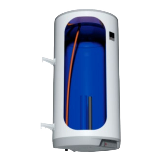
1 PRODUCT TECHNICAL SPECIFICATION 1.1 FUNCTION DESCRIPTION Tank type water heater (the heater hereinafter) is designed for the accumulation heating of service water by electric energy. Water is heated by an electric element in an enamelled thermally insulated tank at the time defined by the power supplier. The element is at the time of heating controlled by a thermostat the temperature of which can be adjusted continuously (within the range between 5 °C and 74 °C). - Page 5 OKCE 80 OKCE 100 OKCE 125 OKCE 160 OKCE 200 TYPE OKHE 80 OKHE 100 OKHE 125 OKHE 160 VOLUME MAX OPERATING OVERPRESSURE IN THE TANK ELECTRICAL CONNECTION 3/N/PE ~ 400V/50Hz RECOMMENDED BREAKER 3x10 A INPUT 4000 EL. PROTECTION IP 44...
-
Page 6: Design And General Heater Dimensions
1.3 DESIGN AND GENERAL HEATER DIMENSIONS The heater tanks are made of a steel plate and tested by 1.5 MPa multiple of operation pressure value. The inside of the receptacle is enamelled. A flange is welded onto the bottom of the tank with a flange lid screwed to it. - Page 7 OKCE 80, OKCE 100, OKCE 125, OKCE 160, OKCE 200 Upper and lower Hinge 200L Upper hinge 50 - 160L 4 anchoring screws 2 anchoring screws Dimensions 450mm and F check before drilling Figure 2 3/4" outer OKCE 80...
- Page 8 OKHE 80, OKHE 100, OKHE 125, OKHE 160 Figure 3 3/4" outer OKHE 80 OKHE 100 OKHE 125 OKHE 160 1050 1235 1000 Table 3 - 8 -...
-
Page 9: Operation And Fitting Instructions
2 OPERATION AND FITTING INSTRUCTIONS 2.1 OPERATING CONDITIONS The tank shall only be used in accordance with the conditions specified on the power plate and in instructions for electric wiring. Besides legally acknowledged national regulations and standards, also conditions for connection defined in local electric and water works have to be adhered to, as well as the installation and operation manual. -
Page 10: Plumbing Fixture
Universal suspension The use of the suspension even for the screw spacing during the replacement with a heater of another type. The heater verticality after the release of the connecting screws can be aligned by means of slight turning. Figure 5 If the hot water heater is mounted in a tight, small space, or in an intermediate ceiling, etc., you have to make sure that the connecting side of the appliance (connections to water supply, area for electric plugging) remained accessible and no heat accumulation occurs. - Page 11 It is necessary to check the safety valve each time before putting it into operation. It is checked by manual moving of the membrane from the seat, turning the make-and-break device button always in the direction of the arrow. After being turned, the button must click back into a notch. Proper function of the make-and-break device results in water draining through the safety valve outlet pipe.
-
Page 12: Electrical Installation
2.4 ELECTRICAL INSTALLATION 2.4.1 GENERAL INFORMATION FOR ELECTRICAL INSTALLATION Perform the connection according to the scheme. Factory connection must not be changed! (Figure 9). In the electric wiring casing remove the partition corresponding with the input wire diameter Ø8 or Ø10 (Figure 8). -
Page 13: Operating Activity
2.5 OPERATING ACTIVITY After the heater is connected to electric network, the heating element starts heating water. The element is turned on and off by a thermostat. After reaching the temperature set, the thermostat switches off the electric circuit and discontinues water heating. The control light signals if the element is in operation (light is on) or if it is off (the light goes out). -
Page 14: Putting Out Of Service, Discharge
2.7 PUTTING OUT OF SERVICE, DISCHARGE If the hot water heater is put out of service for a longer time, or if it is not going to be used it has to be drained and disconnected from the electric supply network on all poles. The switch for the supply lead or the fuse cut-outs have to be shut off. -
Page 15: Most Frequent Function Failures And Their Causes
If water contains too many minerals, an expert has to come to remove the scale that forms inside the tank, as well as free sediments. This has to be performed after one or two years of operation. The cleaning is carried out through the hole in the flange - dismantle the flange lid and clean the tank. -
Page 16: Operation Of Thermostat
Electric circuit closing indicator lamp Thermostat knob Tipping plastic guard Figure 10 Electrical installation covers for heaters OKCE 80, OKCE 100, OKCE 125, OKCE 160 OKHE 80, OKHE 100, OKHE 125, OKHE 160 Electric circuit closing indicator lamp Thermostat knob... -
Page 17: Temperature Setting
Thermostat and no other part of the control panel is not a bearing part which can be used for any handling with the heater. 3.1.1 TEMPERATURE SETTING Water temperature is set by turning the thermostat knob. The desired symbol is adjusted against the fixed point on the control panel (Figure 12, Figure 13). -
Page 18: Important Notices
4 IMPORTANT NOTICES 4.1 INSTALLATION REGULATIONS Without a confirmation of performed electrical installation issued by an authorised company, the warranty certificate shall be void. Check and exchange the Mg anode regularly. You have to apply for approval of a local power supplier to connect the heater. No stop valves can be put between the heater and the safety valve. -
Page 19: Disposal Of Packaging Material And Non-Functioning Product
4.3 DISPOSAL OF PACKAGING MATERIAL AND NON-FUNCTIONING PRODUCT A service fee for providing return and recovery of packaging material has been paid for the packaging in which the product was delivered. The service fee was paid pursuant to Act No 477/2001 Coll., as amended, at EKO-KOM a.s. The client number of the company is F06020274.
Need help?
Do you have a question about the OKCE 80 and is the answer not in the manual?
Questions and answers