Drazice OKC 80 Operation And Installation Manual
Tank-type water heaters
for vertical mounting
Hide thumbs
Also See for OKC 80:
- Operation and installation manual (20 pages) ,
- Operating and installation manual (20 pages) ,
- Operation and installation manual (18 pages)
Table of Contents
Advertisement
OPERATION AND
INSTALLATION MANUAL
TANK-TYPE WATER HEATERS
FOR VERTICAL MOUNTING
OKC 80
OKC 100
OKC 125
OKC 160
OKC 180
OKC 200
Družstevní závody Dražice - strojírna s.r.o.
Dražice 69, 294 71 Benátky nad Jizerou
tel.: +420 / 326 370 990
fax: +420 / 326 370 980
e-mail: prodej@dzd.cz
4 kW/400 V
Combined
OKC 100/1m2
OKC 125/1m2
OKC 160/1m2
OKC 180/1m2
OKC 200/1m2
Electric
OKCE 80
OKCE 100
OKCE 125
OKCE 160
OKCE 180
OKCE 200
Advertisement
Table of Contents

Related Manuals for Drazice OKC 80


Summary of Contents for Drazice OKC 80
-
Page 1: Installation Manual
OPERATION AND INSTALLATION MANUAL TANK-TYPE WATER HEATERS FOR VERTICAL MOUNTING 4 kW/400 V Combined Electric OKC 80 OKCE 80 OKC 100 OKC 100/1m2 OKCE 100 OKC 125 OKC 125/1m2 OKCE 125 OKC 160 OKC 160/1m2 OKCE 160 OKC 180 OKC 180/1m2... -
Page 2: Table Of Contents
CONTENTS TECHNICAL SPECIFICATION OF PRODUCT ....................4 FUNCTION DESCRIPTION ........................4 ADVICE FOR CUSTOMERS ......................... 5 1.2.1 HOT WATER CONSUMPTION ....................5 1.2.2 ENERGY SAVING ........................5 1.2.3 EMERGENCY POWER CONSUMPTION..................5 DESIGN AND GENERAL HEATER DIMENSIONS .................. 6 OPERATION AND FITTING INSTRUCTIONS ....................11 OPERATING CONDITIONS ....................... - Page 3 READ CAREFULLY THE BELOW INSTRUCTIONS PRIOR TO THE INSTALLATION THE HEATER! Dear Customer, The Works Cooperative of Dražice – Machine Plant, Ltd., would like to thank you for your decision to use a product of our brand. With this guide, we will introduce you to the use, construction, maintenance and other information on electrical water heaters.
-
Page 4: Technical Specification Of Product
1 TECHNICAL SPECIFICATION OF PRODUCT 1.1 FUNCTION DESCRIPTION The heater is designed for accumulation heating of service water using electricity or thermal energy via an exchanger (for the combined design only). Water is heated by an electric element (or a heat exchanger) in an enamelled thermally insulated accumulator at the time defined by the power supplier. -
Page 5: Advice For Customers
1.2 ADVICE FOR CUSTOMERS 1.2.1 HOT WATER CONSUMPTION Consumption of hot water in households depends on the number of people, amount of sanitary equipment, length, diameter and insulation of piping in the flat, or on individual habits of users. The cheapest option of water heating comes at the time when the electricity rate is reduced. -
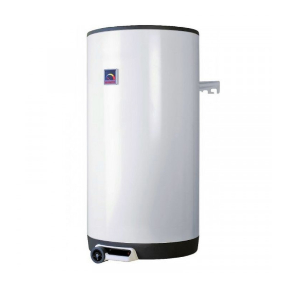
Page 6: Design And General Heater Dimensions
(kWh/ CAPACIT (kWh/ Y CLASS HEATING 24hr/l) Y (l) CONTENTS 24h) (hours) FROM 15°C TO 65°C (kWh) OKC 80 OKC 100; OKC 100/1m OKC 125; OKC 125/1m OKC 160; OKC 160/1m OKC 180; OKC 10.6 180/1m OKC 200; OKC 200/1m... - Page 7 The temperature of water can be set using the thermostat. Heat exchanger(s) is/are welded onto the pressure tank. Description of basic parts of the heater – Figure 1, Figure 2. Heater dimensions – (Figure 1, Figure 2) and (Table 3, Table 4) OKC 80 OKC 100 OKC 125 OKC 160...
- Page 8 TYPE OKC 80 OKC 100 OKC 125 OKC 160 OKC 180 OKC 200 EXCHANGER HEAT 0.41 0.68 0.68 0.68 0.68 0.68 SURFACE RATED THERMAL OUTPUT AT HEATING WATER TEMPERATURE 9000 17000 17000 17000 17000 17000 OF 80°C AND FLOW 720 TIME OF HEATING BY EXCHANGER FROM 10°C...
- Page 9 OKC 80, OKC 100, OKC 125, OKC 160, OKC 180, OKC 200, OKC 100/1m , OKC 125/1m , OKC 160/1m , OKC 180/1m , OKC 200/1m Upper and lower hinge 160,180, Upper hinge and support 200L 4 anchor bolts 80-125L 2 anchor bolts...
- Page 10 Upper and lower hinge Upper hinge and 160,180, 200L support 4 anchor bolts 80-125L Dimensions 450mm and E 2 anchor bolts Check before drilling Figure 2 OKCE OKCE OKCE OKCE 80 OKCE 160 OKCE 180 1046 1235 1187 1287 1041 1230 1182 1282...
-
Page 11: Operation And Fitting Instructions
2 OPERATION AND FITTING INSTRUCTIONS 2.1 OPERATING CONDITIONS The tank shall only be used in accordance with the conditions specified on the performance plate and in instructions for electric wiring. Besides legally acknowledged national regulations and standards, also conditions for connection defined in local electric and water works have to be adhered to, as well as the installation and operation manual. -
Page 12: Plumbing Fixture
Figure 3 2.3 PLUMBING FIXTURE Connection of heaters to plumbing fixtures is illustrated on Figure 4. For potential disconnection of the heater, the service water inlets and outlets must be provided with screw coupling Js 3/4“. Safety valve is mounted on the cold water inlet identified with a blue ring. - Page 13 the heater and the safety valve. During the assembly, follow the guide provided by the safety equipment manufacturer. It is necessary to check the safety valve each time before putting it into operation. It is checked by manual moving of the membrane from the seat, turning the make-and-break device button always to the right.
-
Page 14: Electric Wiring
Heaters must be provided with a discharge valve mounted on the cold service water inlet to the heater for potential disassembly or repair. When assembling the security equipment, follow Standards. 0 - Air outlet valve U – Shut-off valve P1 - Safety valve with backflow flap P2 - Safety valve for heating circuit M - Manometer Z –... -
Page 15: Connection Of Indirect Heater To Hot Water Heating System
Figure 5 2.5 CONNECTION OF INDIRECT HEATER TO HOT WATER HEATING SYSTEM It is recommended to install stop valves on the heating water inlet and outlet (for possible dismantling of the heater). The valves have to be as close to the heater as possible to avoid higher thermal losses (Figure 6). -
Page 16: First Heater Commissioning
2.6 FIRST HEATER COMMISSIONING After connecting the heater to the water supply, the hot water heating system, the electric network, and after testing its safety valve (based on the valve manual attached), the heater may be put into operation. Before opening the power supply, the tank must be filled with water. -
Page 17: Inspection, Maintenance & Care For The Appliance
Drainage of service water shall be performed after closing the shut-off valve in the cold water supply piping (through the discharge valve for safety valve combination), and with simultaneous opening of all hot water valves of connected fittings. Hot water may outflow during the drainage! If there is a risk of frost it has to be considered that not only the water in the hot water heater and in the hot water piping may get frozen but also the water in the entire cold water supply piping. -
Page 18: Most Frequent Function Failures And Their Causes
2.9 MOST FREQUENT FUNCTION FAILURES AND THEIR CAUSES Potential failures – Table 6 FAILURE SYMPTOM SOLUTION LED is on Water is cold the temperature set on the thermostat is too low heating element failure Water is cold LED is not on no supply voltage ... -
Page 19: Operation Of Thermostat
3. OPERATION OF THERMOSTAT 3.1 OPERATING MODES 3.1.1 SERVICING Service devices of heaters of 80 to 200 l capacity are located under the transparent guard of the control panel. (Figure 7). Thermostat knob Electric circuit closing indicator lamp Tipping plastic guard Figure 7 3.1.2 TEMPEATURE SETTING Water temperature is set by turning the thermostat knob. -
Page 20: Limiting The Regulation Range; Locked Settings
3.1.3 LIMITING THE REGULATION RANGE; LOCKED SETTINGS For various safety reasons (unintentional scalding, preventing children or unauthorised person from handling), the regulation range can be limited, or the setting on the thermostat blocked (Figure 9). Regulation limited To block the setting Figure 9 To limit regulation off the thermostat knob (it will be tough at first) and you will find two cylindrical pins Ø2,15mm on... -
Page 21: Disposal Of Packaging Material And Functionless Product
All electric installation handling, adjustment and replacement of the regulation elements shall only be performed by an authorised service company. The thermal fuse must not be turned off! In case of thermostat defect, the thermal fuse interrupts electric power input to the heating element if the water temperature in the heater exceeds 90 °C. ...
Need help?
Do you have a question about the OKC 80 and is the answer not in the manual?
Questions and answers