Table of Contents
Advertisement
Quick Links
OPERATION AND
INSTALLATION MANUAL
TANK-TYPE WATER HEATERS FOR VERTICAL
Družstevní závody Dražice - strojírna s.r.o.
Dražice 69, 294 71 Benátky nad Jizerou
tel.: +420 / 326 370 990
fax: +420 / 326 370 980
e-mail: prodej@dzd.cz
MOUNTING
Electric water heaters
OKCE 50
OKCE 80
OKCE 100
OKCE 125
OKCE 160
OKHE 80
OKHE 100
OKHE 125
OKHE 160
Advertisement
Table of Contents

Related Manuals for Drazice OKCE 50


Summary of Contents for Drazice OKCE 50
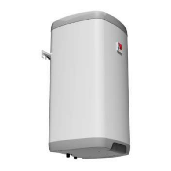
- Page 1 OPERATION AND INSTALLATION MANUAL TANK-TYPE WATER HEATERS FOR VERTICAL MOUNTING Electric water heaters OKCE 50 OKCE 80 OKHE 80 OKCE 100 OKHE 100 OKCE 125 OKHE 125 OKCE 160 OKHE 160 Družstevní závody Dražice - strojírna s.r.o. Dražice 69, 294 71 Benátky nad Jizerou tel.: +420 / 326 370 990...
-
Page 2: Table Of Contents
CONTENTS TECHNICAL SPECIFICATION OF PRODUCT ....................4 FUNCTION DESCRIPTION ........................4 ADVICE FOR CUSTOMERS ........................4 1.2.1 HOT WATER CONSUMPTION ..................... 4 1.2.2 ENERGY SAVING ......................... 4 1.2.3 EMERGENCY POWER CONSUMPTION ..................4 DESIGN AND GENERAL HEATER DIMENSIONS ................... 6 OPERATION AND FITTING INSTRUCTIONS .................... - Page 3 READ CAREFULLY THE BELOW INSTRUCTIONS PRIOR TO THE INSTALLATION THE HEATER! Dear Customer, The Works Cooperative of Dražice – Machine Plant, Ltd., would like to thank you for your decision to use a product of our brand. With this guide, we will introduce you to the use, construction, maintenance and other information on electrical water heaters.
-
Page 4: Technical Specification Of Product
1 TECHNICAL SPECIFICATION OF PRODUCT 1.1 FUNCTION DESCRIPTION The heater is designed for accumulation heating of service water using electricity. Water is heated by an electric element in an enamelled thermally insulated tank at the time defined by the power supplier. The element is at the time of heating controlled by a thermostat the temperature of which can be adjusted continuously (within the range between 5°C and 74°C). -
Page 5: Okce
OKCE OKCE OKCE OKCE OKCE OKCE OKCE TYPE 100/ 125/ 160/ OKHE OKHE OKHE OKHE CAPACITY 152/155 MAX OPERATING OVERPRESSURE IN THE TANK MAX OPERATING OVERPRESSURE IN EXCHANGER* ELECTRIC 1 PE-N 230V/50Hz CONNECTION INPUT 2000 2200 IP 45 EL.PROTECTION MAX HSW °C TEMPERATURE RECOMMENDED... -
Page 6: Design And General Heater Dimensions
1.3 DESIGN AND GENERAL HEATER DIMENSIONS The heater tank is made of a steel plate and tested by 0.9 MPa overpressure. The inside of the tank is enamelled. A flange is welded onto the bottom of the tank with a flange lid screwed to it. A sealing ring is inserted between the flange lid and the flange. - Page 7 Technical description: OKCE 50 – 200, OKHE 80 - 160 Upper suspension and support 50-160L 2 anchor bolts Upper lower suspension 180, 200 I Figure 2 4 anchor bolts Dimensions 450mm and E Double check before drilling OKCE OKCE 80/...
-
Page 8: Operation And Fitting Instructions
2 OPERATION AND FITTING INSTRUCTIONS 2.1 OPERATING CONDITIONS The tank shall only be used in accordance with the conditions specified on the power plate and in instructions for electric wiring. Besides legally acknowledged national regulations and standards, also conditions for connection defined in local electric and water works have to be adhered to, as well as the installation and operation manual. -
Page 9: Plumbing Fixture
If the hot water heater is mounted in a tight, small space, or in an intermediate ceiling, etc., you have to make sure that the connecting side of the appliance (connections to water supply, area for electric plugging) remained accessible and no heat accumulation occurs. Free space of up to 500 mm from the bottom edge of the heater has to be available under the heater. - Page 10 Please find necessary pressure values in the below Table 3. For proper safety valve operation, a backflow valve (Figure 4) must be mounted on the inlet pipes, preventing spontaneous heater draining and hot water penetrating back into the water main. We recommend that the hot water distribution from the heater was as short as possible to minimise heat losses.
-
Page 11: Electric Installation
2.4 ELECTRIC INSTALLATION 2.4.1 GENERAL INFORMATION FOR ELECTRIC INSTALLATION Perform the connection according to the scheme. Factory connection must not be changed! (Figure 6 In the electric wiring casing remove the partition corresponding with the input wire diameter of 8 or 10 (Figure 5). -
Page 12: Connection Of Heater To Hot Water Heating System
2.5 CONNECTION OF HEATER TO HOT WATER HEATING SYSTEM After the heater is connected to electric network, the heating element starts heating water. The element is turned on and off by a thermostat. After reaching the temperature set, the thermostat switches off the electric circuit and thus discontinues water heating. -
Page 13: Putting Out Of Service, Discharge
Procedure of putting the heater into operation: 1. Check the water main and wiring. Check proper placement of operating and safety thermostat sensors. The sensors must be inserted all the way in; first the operating and then the safety thermostat. 2. -
Page 14: Inspection, Maintenance & Care For The Appliance
2.8 INSPECTION, MAINTENANCE & CARE FOR THE APPLIANCE During the heating process the water that increases its volume during the heating must visibly drip off the safety valve outlet (in non-pressurised connection this water drips off the combination faucet valve). In full heating (about 74°C) the volumetric water gain is approx. -
Page 15: Most Frequent Function Failures And Their Causes
2.9 MOST FREQUENT FUNCTION FAILURES AND THEIR CAUSES FAILURE SYMPTOM CONTROL LIGHT SOLUTION Water is cold light on The temperature set on the thermostat is too low; heating element failure Water is cold light off No supply voltage; ... -
Page 16: Operation Of Thermostat
3 OPERATION OF THERMOSTAT 3.1 SERVICING 3.1.1 SERVICE HEATER DEVICES The service devices are located under the plastic guard of the control panel (Figure 8). Thermostat knob Electric circuit closing indicator lamp Tipping plastic guard Figure 8 3.1.2 TEMPERATURE SETTING Water temperature is set by turning the thermostat knob. -
Page 17: Important Notices
4 IMPORTANT NOTICES 4.1 INSTALLATION REGULATIONS Without a confirmation of performed electrical installation issued by an authorised company, the warranty certificate shall be void. Check and exchange the Mg anode regularly. You have to apply for approval of a local power supplier to connect the heater. No stop valves can be put between the heater and the safety valve. -
Page 18: Product Accessories
5 PRODUCT ACCESSORIES The product is supplied together with a safety valve and a thermometer. The above parts are packed and placed in the packaging in the top part of the heater. It is in your own interest to check the completeness of the accessories. 12-2-2015 - 18 -...
Need help?
Do you have a question about the OKCE 50 and is the answer not in the manual?
Questions and answers