Table of Contents
Advertisement
Quick Links
OPERATING AND
INSTALLATION MANUAL
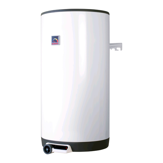
TANK-TYPE WATER HEATER FOR VERTICAL
OKCE 50
OKCE 80
OKCE 100
OKCE 125
OKCE 160
Družstevní závody Dražice - strojírna s.r.o.
Dražice 69, 294 71 Benátky nad Jizerou
Phone.: +420 /326 370 990
Fax: +420 / 326 370 980
e-mail: prodej@dzd.cz
MOUNTING
Electric water heaters
OKCE 200
OKHE 80
OKHE 100
OKHE 125
OKHE 160
Advertisement
Table of Contents


Need help?
Do you have a question about the OKCE 50 and is the answer not in the manual?
Questions and answers