
Related Manuals for Festo EXCM-10-***-E


Summary of Contents for Festo EXCM-10-***-E
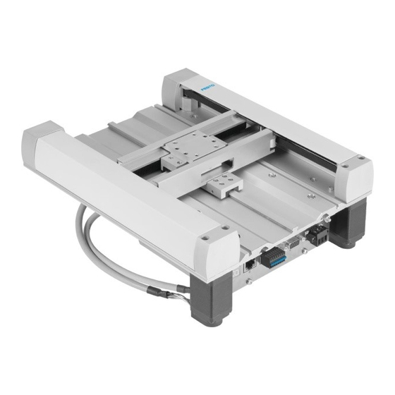
- Page 1 Planar surface gantry with controller EXCM-10/-30-...-E Description Commissioning 8068047 1612b [8068049]...
- Page 2 Text designations: • Activities that may be carried out in any order 1. Activities that should be carried out in the order stated – General lists è Result of an action/References to more detailed information Festo – EXCM-10/-30-...-E-EN – 1612b –...
-
Page 3: Table Of Contents
........... . Festo – EXCM-10/-30-...-E-EN – 1612b – English... - Page 4 ............Festo – EXCM-10/-30-...-E-EN – 1612b – English...
- Page 5 ..............Festo – EXCM-10/-30-...-E-EN – 1612b – English...
- Page 6 You can find the specifications of the version status as follows: – Hardware version and firmware version in the Festo Configuration Tool (FCT) with act ive online connection to the controller on the “Controller” page.
-
Page 7: Safety And Requirements For Product Use
• Switch off the supply voltage before mounting and installation work. Switch on sup ply voltage only when mounting and installation work are completely finished. • Never unplug or plug in a product when powered! • Observe the handling specifications for electrostatically sensitive devices. Festo – EXCM-10/-30-...-E-EN – 1612b – English... -
Page 8: Intended Use
Intended use The controller is used for controlling planar surface gantries with a single rotating toothed belt in ac cordance with the Festo catalogue and is used exclusively for controlling planar surface gantries of type EXCM. The functions of the controller are documented in this description. -
Page 9: Requirements For Product Use
Standards and test values that the product complies with and fulfils can be found in appendix (è A Technical data). The product-relevant EU directives can be found in the declaration of conformity. Certificates and the declaration of conformity for this product (è www.festo.com). Festo – EXCM-10/-30-...-E-EN – 1612b – English... -
Page 10: Overview
Overview Overview General properties – FCT-compatible: configuration, parameterisation and backup via Festo Configuration Tool (FCT) – Energy-optimised operation and low heat development – Separated load and logic supply (renewed homing not required after emergency stop) – LED-display components for representation of device and communication status –... -
Page 11: Monitoring Functions
+24 V +24 V Logic voltage Driver supply +24 V Activation/switch-off of the driver supply DIAG1 DIAG2 Driver supply monitoring PWM driver μP step Fig. 2.2 Switch-off functions - block diagram Festo – EXCM-10/-30-...-E-EN – 1612b – English... -
Page 12: Drive Functions
Simultaneously, the switch-off delay time be gins to run. The controller continues to control the position. Then the controller end stage is switched off after the switch-off delay. Festo – EXCM-10/-30-...-E-EN – 1612b – English... -
Page 13: Operating Modes
Additional possible functions in record selection are jogging as well as homing. The I/O, CANopen or Ethernet interface can be used as a control interface. Parameter records can only be parameterised via the Festo Configuration Tool (FCT) (è 5.3.6 Record table). -
Page 14: Measuring Reference System
The controller works in the range of the drive controller with encoder increments (EINC). In contrast, so-called interface increments (SINC) are used at all user interfaces and in the field of internal data management. 1 mm = 1000 SINC 1 EINC k 19.5 μm Festo – EXCM-10/-30-...-E-EN – 1612b – English... -
Page 15: Selection Of The Coordinate System
Axis zero point at corner point 3 Fig. 2.6 Axis zero point at corner point 4 Establishment of the axis zero point is performed exclusively through the Festo Configur ation Tool (FCT) (è 5.3.5 Component settings) . Festo – EXCM-10/-30-...-E-EN – 1612b – English... -
Page 16: Dimension Reference Points
= AZ + b Negative software limit = AZ + d Positive software limit = AZ + f TP/AP Target position/actual position = PZ + c = AZ + b + c Tab. 2.2 Calculation rules Festo – EXCM-10/-30-...-E-EN – 1612b – English... -
Page 17: General Structure
General structure 2.8.1 Control interfaces The controller has three control interfaces in order to communicate with a higher-order controller. The active control interface is established via the Festo Configuration Tool (FCT) (è 5.3.5 Component settings). – I/O interface – CANopen interface –... -
Page 18: Led Display Components
Illuminated red Error is present Warning is present or controller Flashes red (–– –– –– …) identification is active (è 5.3.9 Controller identification) Tab. 2.3 Possible statuses of the LED display - device Festo – EXCM-10/-30-...-E-EN – 1612b – English... - Page 19 (Node Guarding). Tab. 2.5 LED indicator COM - CANopen operation COM - CVE operation Status Significance (green/yellow/red) Flashes green (– · – · …) Communication active. Tab. 2.6 LED indicator COM - CVE operation Festo – EXCM-10/-30-...-E-EN – 1612b – English...
-
Page 20: 7-Segments Display
7-segments display, it may be the case that not all malfunctions are displayed. • Read the diagnostic memory (è 7.1 Diagnostic memory) in order to have all mes sages displayed. Festo – EXCM-10/-30-...-E-EN – 1612b – English... -
Page 21: System Overview
Ï Ï Ï Ï Ï Ï Ï Ï Ï Ï Higher-order control level: PLC/IPC Controller level Parameterisation and commissioning level: Drive level: planar surface gantry Festo Configuration Tool (FCT) Fig. 2.11 System overview Festo – EXCM-10/-30-...-E-EN – 1612b – English... -
Page 22: Emergency Stop Concept
The load voltage is switched off. The effective load on the drive may continue to load voltage move due to inertia, or it will fall if mounted in a vertical or sloping position. Festo – EXCM-10/-30-...-E-EN – 1612b – English... -
Page 23: Assembly
• Observe the IP protection class of the controller and of the plugs and cables (è A.1 General data or documentation of the cables). Dimensions of the controller Fig. 3.1 Dimensions Dimensions [mm] Tab. 3.1 Festo – EXCM-10/-30-...-E-EN – 1612b – English... -
Page 24: Mounting The Controller
• Observe the maximum screw-in depth in the mounting slots of 6 mm. • When tightening the screws, observe the recommended tightening torque of 1±0.1 Nm. Fig. 3.2 Distances of the mounting slots Dimensions [mm] Tab. 3.2 Festo – EXCM-10/-30-...-E-EN – 1612b – English... -
Page 25: Electrical Installation
To ensure compliance with the IP protection class (if required): • Please note that the specified IP protection class is only achieved if all plugs are assigned. Observe the tightening torques in the documentation of the cables and plugs used. Festo – EXCM-10/-30-...-E-EN – 1612b – English... -
Page 26: Connections And Interfaces
Network cable, RJ45 plug; Cat. 5 (or better) 6 CANopen interface [X3] Prepared by the customer 1) Subject to change. Only the current specifications in the Festo catalogue are relevant: www.festo.com Tab. 4.1 Cables for connections on the front (accessories) Festo – EXCM-10/-30-...-E-EN – 1612b – English... - Page 27 NEBM-M12G5-E-…-N-C1G6 (without brake) 7 Encoder motor 2 NEBM-S1G9-K-0.25-N-L2G10 NEBM-M12G8-E-…-N-S1G9 1) Subject to change. Only the current specifications in the Festo catalogue are relevant: www.festo.com Tab. 4.2 Cables for connections on the back cover (accessories) Festo – EXCM-10/-30-...-E-EN – 1612b – English...
-
Page 28: Power Supply [X1]
Damage to the device The power supply inputs have no special protection against overvoltage. • Make sure the permissible voltage tolerance is never exceeded. Technical data of the voltage supply (è A.2 Electrical data). Festo – EXCM-10/-30-...-E-EN – 1612b – English... -
Page 29: Functional Earth
Scanning rate [ms] Input current at nominal input voltage per input [mA] Max. permissible input voltage Outputs (secure against short circuit) Maximum current per output [mA] Tab. 4.5 Specification of the I/O interface [X2] Festo – EXCM-10/-30-...-E-EN – 1612b – English... -
Page 30: Canopen Interface [X3]
Ethernet interface [X5] The Ethernet interface can thereby be used both for control via the FCT and also for operation via the function CVE. Note • Use a network cable of category 5 or better. Festo – EXCM-10/-30-...-E-EN – 1612b – English... -
Page 31: Encoder Connection
BR+ is switched (24 V load) 1) Next to the motor connections is an M4 threaded pin to connect the screening of the motor cable through a cable lug Tab. 4.9 Motor connection Festo – EXCM-10/-30-...-E-EN – 1612b – English... -
Page 32: Commissioning With The Fct
Interruption of ongoing tasks due to inadequate load voltage supply. • Make sure that the tolerance of the load voltage supply at the input of the controller is complied with under full load (è A.2 Electrical data). Festo – EXCM-10/-30-...-E-EN – 1612b – English... -
Page 33: Network Connection Via Ethernet
Connection to PC/laptop 5.2.2 Network settings Network settings upon delivery Parameters Value 192.168.178.1 DHCP server Active Port (FCT) 7508 Port (CVE) 49700 Subnet mask 255.255.255.0 Gateway 0.0.0.0 (none) Tab. 5.1 Network settings upon delivery Festo – EXCM-10/-30-...-E-EN – 1612b – English... -
Page 34: Safety In The Network
FCT on the “Error management” page (malfunction number 0x32). The typical timeout is 1 s, but can be longer in slow networks, since the timeout is adjusted dynamically to the transmission rate. Festo – EXCM-10/-30-...-E-EN – 1612b – English... -
Page 35: The Festo Configuration Tool (Fct)
After installation of the FCT software on your PC/laptop, you can start it in two ways. • Double click on the FCT icon on your desktop. • Select the entry [Festo Software] [Festo Configuration Tool] in the start menu from the list of pro grams. -
Page 36: Creating A New Project
• Choose a coordinate system by determining the position of the axis zero point (è 2.7 Measuring reference system). • Specify the project zero point and the SW end positions (positive/negative) of both axes (è 2.7 Measuring reference system). Festo – EXCM-10/-30-...-E-EN – 1612b – English... -
Page 37: Record Table
(PRA) – Target position X and target position Y – Speed and acceleration – Comments (optional) Records are parameterised exclusively via the Festo Configuration Tool (FCT). 5.3.7 Teaching The current position can be taken over as parameters through the FCT: 1. -
Page 38: Firmware Update
With firmware changes, the network settings are reset to the delivery status (è 5.2.2 Network settings). • Carry out a firmware update only upon instruction by Festo Service in order to avoid unforeseeable behaviour by the planar surface gantry due to a possibly defective configuration. -
Page 39: Operation
• But observe the maintenance information of the planar surface gantry as well as possible additional components. Disposal and environment Note Environmentally friendly disposal • Observe the local regulations for environmentally friendly disposal of electronic components. Festo – EXCM-10/-30-...-E-EN – 1612b – English... -
Page 40: Communication Principle, General
Communication between a higher-order controller and the controller takes place in all operating modes through the FHPP protocol (Festo Handling and Positioning Profile) with cyclical data exchange of 8 bytes of output and 8 bytes of input data each. Output data are transferred via the control bytes CCON and CPOS and the input data via the status bytes SCON and SPOS. -
Page 41: Description Of The Control Bytes Ccon/Cpos
AXSEL. Reserved Reserved, must be 0. Reserved Reserved, must be 0. Reserved Reserved, must be 0. Tab. 6.6 Control byte CPOS Festo – EXCM-10/-30-...-E-EN – 1612b – English... -
Page 42: Description Of The Status Bytes Scon/Spos
Reserved Drive is moving Speed of the axis < limit value Speed of the axis >= limit value Reserved Reserved Reserved Reserved Homing Homing required Reference information present Tab. 6.8 Status byte SPOS Festo – EXCM-10/-30-...-E-EN – 1612b – English... -
Page 43: Timing Diagram
Reaction to 4: START = 0 (control byte CPOS bit 1) Reaction to 5: ACK = 0 (status byte SPOS bit 1) Positioning job completed: MC = 1 (status byte SPOS bit 2) Fig. 6.1 Timing diagram Festo – EXCM-10/-30-...-E-EN – 1612b – English... -
Page 44: Control Via I/O Interface
No malfunction Malfunction is present Output: acknowledgment Ready to start Positioning started Output: motion complete Positioning job active Positioning job completed Reference potential Tab. 6.9 Description of the input and output interface [X2] Festo – EXCM-10/-30-...-E-EN – 1612b – English... -
Page 45: Examples
– A low signal is applied to Pin 13 as soon as the positioning job has been started (ACK = 1). – As soon as the target position is reached, a low signal is applied to Pin 14 (MC = 1). Festo – EXCM-10/-30-...-E-EN – 1612b – English... -
Page 46: Controller Via Canopen Interface
• Use the EDS file on the accompanying data storage medium for configuration of the controller in a CANopen network. You can find a current EDS file on the Festo Internet page (è www.festo.com). Festo – EXCM-10/-30-...-E-EN – 1612b – English... -
Page 47: Examples
– As soon as the reference position is reached, bit 2 and bit 7 in the control byte SPOS must be set to the value 1 (MC = 1 and REF = 1). Homing is completed. Festo – EXCM-10/-30-...-E-EN – 1612b – English... - Page 48 • Set the bit 0 in the control byte CPOS to the value 0 (ABS/REL = 0). Positioning relative: • Set the bit 0 in the control byte CPOS to the value 1 (ABS/REL = 1). Festo – EXCM-10/-30-...-E-EN – 1612b – English...
- Page 49 5. Reset the bit 1 in the control byte CPOS to the value 0 (START = 0) as soon as bit 1 in the status byte SPOS has the value 1 (ACK = 1). Festo – EXCM-10/-30-...-E-EN – 1612b – English...
-
Page 50: Control Via Ethernet (Cve)
With the function “Control via Ethernet” (CVE), the controller can be controlled via the Ethernet inter face. The controller is pre-parameterised for this purpose with the Festo Configuration Tool (FCT). It is possible to start both homing and positioning jobs via CVE. -
Page 51: Cve Protocol
Tab. 6.16. As both directions concern an endless TCP data stream, the individual messages must be filtered out from this. Specification and strict compliance with the message length are required for this. Festo – EXCM-10/-30-...-E-EN – 1612b – English... - Page 52 Index of the CVE object to be read. 0x0F 0x10 Object subindex UINT08 Subindex of the CVE object to be read. 0x11 Reserved UINT08 Placeholder (initialise with 0). Tab. 6.13 Request “Read CVE object” Festo – EXCM-10/-30-...-E-EN – 1612b – English...
- Page 53 Data type of the read CVE object. 0x12 Data byte 1 corresponding Value of the read CVE object. to data type of … Data byte K the CVE object Tab. 6.14 Response “Read CVE object” Festo – EXCM-10/-30-...-E-EN – 1612b – English...
- Page 54 UINT08 Data type of the CVE object to be written. 0x12 Data byte 1 corresponding Value to data type of … Data byte K the CVE object Tab. 6.15 Request “Write CVE object” Festo – EXCM-10/-30-...-E-EN – 1612b – English...
- Page 55 Data type of the written CVE object. If an attempt has been made to write an object with an invalid data type, the correct data type is returned. Tab. 6.16 Response “Write CVE object” Festo – EXCM-10/-30-...-E-EN – 1612b – English...
- Page 56 The CVE object cannot be written, as it is password Remove password protection via FCT. protected. 0xE0 Control interface is blocked by FCT. Enabling the control interface in the FCT. Tab. 6.17 Confirmation (acknowledge) Festo – EXCM-10/-30-...-E-EN – 1612b – English...
-
Page 57: Examples
– As soon as this status has been reached, bit 1 in the SCON status byte (CVE object 239/0) is set to value 1 (OPEN = 1). The operation is enabled (controlled status). Festo – EXCM-10/-30-...-E-EN – 1612b – English... - Page 58 4. Reset the bit 1 in the control byte CPOS (CVE object 240/0) to the value 0 (START = 0) as soon as bit 1 in the status byte SPOS (CVE object 239/0) has the value 1 (ACK = 1). Festo – EXCM-10/-30-...-E-EN – 1612b – English...
- Page 59 5. Reset the bit 1 in the control byte CPOS (CVE object 240/0) to the value 0 (START = 0) as soon as bit 1 in the status byte SPOS (CVE object 239/0) has the value 1 (ACK = 1). Festo – EXCM-10/-30-...-E-EN – 1612b – English...
-
Page 60: Diagnostics
You can read the diagnostic memory via the Festo Configuration Tool (FCT). • Tab [Diagnostics] [“Read” button] Deleting the diagnostic memory The diagnostic memory can be deleted via the Festo Configuration Tool (FCT), whereby a “switch-on event” (malfunction 3Dh) is generated. The malfunction counter is not reset thereby. Types of malfunctions Malfunctions are distinguished between errors, warnings and information, which have different priorit... -
Page 61: Error Messages
1) è 7.4.2 Table of error messages Tab. 7.1 General error messages CANopen-specific error messages LED indicator Malfunction Priority No bus cable connected or no parameters configured. Bus OFF Warning Limit or Node Guarding Tab. 7.2 CANopen-specific error messages Festo – EXCM-10/-30-...-E-EN – 1612b – English... -
Page 62: Malfunctions: Causes And Remedy
Tab. 7.3 Error responses 7.4.2 Table of error messages You can parameterise the error messages via the Festo Configuration Tool (FCT) on the page “Parameterise error management”. Explanations for table of error messages: Can be parameterised as: F/W/I = fault/warning/information (è... - Page 63 An error has occurred during evaluation of the encoder. The current position values may be incorrect. • Execute a software reset with commutation angle search and homing. – Acknowledgement option: Cannot be acknowledged, software reset required. Parameterisable error response(s): A Festo – EXCM-10/-30-...-E-EN – 1612b – English...
- Page 64 • Travel the respective axis of the planar surface gantry in a positive direction through jog opera tion. – Acknowledgement option: Error can be acknowledged. Parameterisable error response(s): A, B, C, E, F Festo – EXCM-10/-30-...-E-EN – 1612b – English...
- Page 65 • Check the load voltage; measure voltage directly at the controller input. • In the event of a defective internal braking resistor: Replace the controller. – Acknowledgement option: Error can be acknowledged. Parameterisable error response(s): A, B Festo – EXCM-10/-30-...-E-EN – 1612b – English...
- Page 66 • Check parameterisation of the MC window. • Make sure that the drive is at rest before the start of positioning. – Acknowledgement option: Error can only be acknowledged after the cause is eliminated. Parameterisable error response(s): A Festo – EXCM-10/-30-...-E-EN – 1612b – English...
- Page 67 • Check the target data. • Check positioning area. • Check type of travel record (absolute/relative) – Acknowledgement option: Error can only be acknowledged after the cause is eliminated. Parameterisable error response(s): B, C, E, F Festo – EXCM-10/-30-...-E-EN – 1612b – English...
- Page 68 • Ascertain the version of your hardware. You can ascertain the compatible firmware designs and download the appropriate firmware from the Festo website. – For parameterisation as an error: The error can only be acknowledged after the cause is elimin...
- Page 69 • Deactivate the “Torque off ” function: Apply a voltage +24 V at Pin 2 of the emergency stop inter face [X4]. – Acknowledgement option: Error can only be acknowledged after the cause is eliminated. Parameterisable error response(s): A Festo – EXCM-10/-30-...-E-EN – 1612b – English...
- Page 70 The start-up event does not occur if the preceding entry in the diagnostic memory has already been a start-up event. • This event is only used for improved documentation of the malfunctions. Festo – EXCM-10/-30-...-E-EN – 1612b – English...
- Page 71 An internal firmware error has been detected. • Contact Festo Service. – Acknowledgement option: Error can only be acknowledged after the cause is eliminated. Parameterisable error response(s): A Tab. 7.4 Table of error messages Festo – EXCM-10/-30-...-E-EN – 1612b – English...
-
Page 72: Problems With The Ethernet Connection
Error in the power supply. • Observe the tolerances of the electrical data in the appendix (è A.2 Electrical data). Tab. 7.5 Other problems and remedies Festo – EXCM-10/-30-...-E-EN – 1612b – English... -
Page 73: A Technical Data
IEC/DIN EN 60204-1) Encoder resolution Starting at 500 pulses/revolution, through the internal electronic multiplication result in 2000 pulses/revolution (maximum encoder resolution 19μm) è Operating instructions of the drives Max. speed and torque of the motors Festo – EXCM-10/-30-...-E-EN – 1612b – English... -
Page 74: Bcanopen
Life time factor uint8 Factor for monitoring time 1014h COB-ID emergency ob uint32 COB-ID of the emergency object ject Default: 128 + Node-ID 1015h Inhibit time EMCY uint16 Inhibit time for emergency message Default: 0 Festo – EXCM-10/-30-...-E-EN – 1612b – English... - Page 75 FHPP control word uint32 0x30200008 CCON/CPOS Error number uint32 0x30210008 Actual position X uint32 0x30022008 Actual position Y uint32 0x30230008 2066h Version uint16 2072h Serial number of the String controller 20FDh User’s device name String Festo – EXCM-10/-30-...-E-EN – 1612b – English...
- Page 76 Dependent on the operating mode: or path speed Record selection: target record no. 0 … 31 Direct mode: speed [mm/s] 3002h Target position X-axis int16 Unit [0.1 mm] 3003h Target position Y-axis int16 Unit [0.1 mm] Festo – EXCM-10/-30-...-E-EN – 1612b – English...
- Page 77 Record selection: record and error number Direct mode: error number (Error number 0xFF = no error) 3022h Actual position X-axis int16 Unit [0.1 mm] 3023h Actual position Y-axis int16 Unit [0.1 mm] Tab. B.1 CANopen object overview Festo – EXCM-10/-30-...-E-EN – 1612b – English...
-
Page 78: C Control Via Ethernet (Cve)
In the record selection operating mode, the current record number is in the high byte. With direct mode, the high byte = 0. Values: 0 … 255 Default: 255 (255 is not an error, values are in the low byte) Festo – EXCM-10/-30-...-E-EN – 1612b – English... - Page 79 Index 304 Subindex 1 Setpoint position Y FHPP SINT32 R/-/-/-/- The current setpoint position Y is calculated by the controller. Unit: SINC (1 mm = 1000 SINC) Values: –2147483648 … 2147483647 Default: 0 Festo – EXCM-10/-30-...-E-EN – 1612b – English...
- Page 80 Acceleration for a direct positioning job. If a new acceleration value is not written, the value last used is taken. Unit: SINC/s² (1 mm = 1000 SINC) Values: –2147483647 … 2147483647 Default: 0 Festo – EXCM-10/-30-...-E-EN – 1612b – English...
-
Page 81: D Glossary
Parameterisation and commissioning software (FCT = Festo Configuration Tool) FHPP Communication protocol for data exchange (FHPP = Festo Handling and Positioning Profile) Following error Calculated deviation during execution of a positioning record between the target position (in accordance with previously calculated course of the path) and the actual position. - Page 82 Glossary Festo – EXCM-10/-30-...-E-EN – 1612b – English...
- Page 84 Copyright: Festo AG & Co. KG Postfach 73726 Esslingen Germany Phone: +49 711 347-0 Fax: +49 711 347-2144 e-mail: service_international@festo.com Reproduction, distribution or sale of this document or communica tion of its contents to others without express authorization is Internet: prohibited.
Need help?
Do you have a question about the EXCM-10-***-E and is the answer not in the manual?
Questions and answers