
Related Manuals for Festo CMMS-AS G2 Series


Summary of Contents for Festo CMMS-AS G2 Series
- Page 1 Motorcontroller CMMS-AS-...-G2 Description Assembly and installation 8026141 1310NH...
- Page 2 Essential or useful accessories. Information on environmentally sound usage. Text designations: • Activities that may be carried out in any order. 1. Activities that should be carried out in the order stated. – General lists. Festo – GDCP-CMMS-AS-G2-HW-EN – 1310NH – English...
-
Page 3: Table Of Contents
..............Festo – GDCP-CMMS-AS-G2-HW-EN – 1310NH – English... - Page 4 ........... . . Festo – GDCP-CMMS-AS-G2-HW-EN – 1310NH – English...
- Page 5 Before using a newer firmware version, check to see if a newer version of the FCT plug-in or user documentation is available Support Portal: http://www.festo.com/sp. Service Please consult your regional Festo contact if you have any technical problems. Product identification Rating plate CMMS-AS-…-G2 Meaning Type designation CMMS-AS-…-G2...
-
Page 6: Cmms-As
CMMS-AS-...-G2 Type codes cmms – – – – Interfaces cmms Motor controller, standard Motor technology AC synchronous Nominal current Input voltage 230 V AC Generation Second generation Fig. 1 Type codes Festo – GDCP-CMMS-AS-G2-HW-EN – 1310NH – English... - Page 7 Description of the DeviceNet interface of the motor controller P.BE-CMMS-FHPP-DN-SW-... Help on the FCT plug-in CMMS-AS User interface and functions of the CMMS-AS plug-in for the Festo Configuration Tool www.festo.com Tab. 2 Documentation for the motor controller CMMS-AS-...-G2 Festo – GDCP-CMMS-AS-G2-HW-EN – 1310NH – English...
-
Page 8: Safety And Requirements For Product Use
• Perform a risk assessment in accordance with the EC machinery directive. • Based on this risk assessment, design the safety system for the entire machine, taking into account all integrated components. This also includes the electric drives. Bypassing of safety equipment is impermissible. Festo – GDCP-CMMS-AS-G2-HW-EN – 1310NH – English... -
Page 9: Intended Use
– as an installed device in a control cabinet. In the event of damage caused by unauthorised manipulation or other than intended use, the guarantee is invalidated and the manufacturer is not liable for damages. Festo – GDCP-CMMS-AS-G2-HW-EN – 1310NH – English... -
Page 10: Requirements For Product Use
The motor controller carries the CE marking; for standards and test values Appendix A.1. The EU directives that are relevant for the product can be found in the declaration of conformity. Certificates and the declaration of conformity for this product www.festo.com. Festo – GDCP-CMMS-AS-G2-HW-EN – 1310NH – English... -
Page 11: Product Overview
PC with serial connecting cable for parameterisation and commissioning with the Festo Configuration Tool (FCT), plug-in CMMS-AS Motor EMMS-AS with encoder, cable set (motor and encoder cable NEBM) Fig. 2.1 Complete structure CMMS-AS-...-G2 Festo – GDCP-CMMS-AS-G2-HW-EN – 1310NH – English... -
Page 12: Scope Of Delivery
Number Component Motor controller CMMS-AS-...-G2 Operator package – Brief description – CD-ROM with parameterisation software “Festo Configuration Tool” (FCT), product documentation, S7 module, PROFIBUS device master data (GSD), electronic data sheet (EDS), firmware Plug assortment NEKM-C-4 (plugged onto connections) Mounting bracket Tab. -
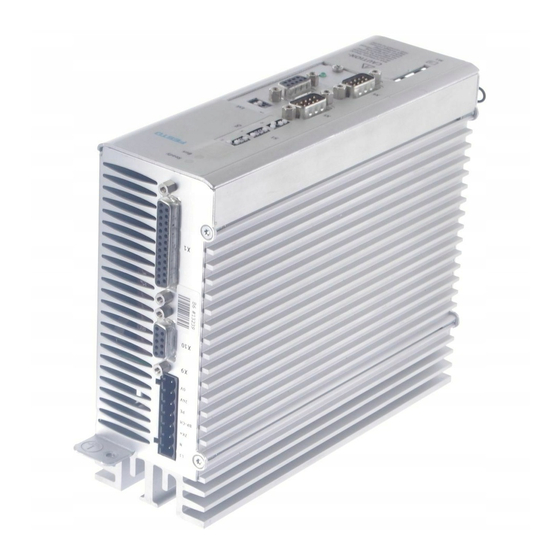
Page 13: Device View
[S1]: DIP switches for fieldbus settings and firmware update [EXT]: Slot for optional control interfaces (PROFIBUS DP, DeviceNet) [M1]: SD- memory card [X4]: CAN-Bus [X5]: RS232/RS485 Earthing screw (central PE connection) Fig. 2.2 Front view of CMMS-AS-...-G2 Festo – GDCP-CMMS-AS-G2-HW-EN – 1310NH – English... - Page 14 Product Overview [X9] Power supply [X10] Master/slave (bi-directional interface) [X1] I/O interface Fig. 2.3 Top view of CMMS-AS-...-G2 [X3] STO interface [X2] Encoder [X6] Motor Shield connection terminal Fig. 2.4 Bottom view of CMMS-AS-...-G2 Festo – GDCP-CMMS-AS-G2-HW-EN – 1310NH – English...
-
Page 15: Display And Control Elements
Warnings are automatically acknowledged when the cause is no longer present. Error messages are acknowledged via: – the parameterisation software FCT – the fieldbus (control word) – or a decreasing edge at [X1] DIN5. Festo – GDCP-CMMS-AS-G2-HW-EN – 1310NH – English... -
Page 16: Led Displays
S1.9 … 10 ON/OFF (example) Significance DIP switch S1.9 is the low-order bit. 125 kBit/s 250 kBit/s (example) 500 kBit/s 1000 kBit/s 1) Additional information Functional description GDCP-CMMS-AS-G2-FW-...: fieldbus configuration. Tab. 2.6 CAN-Bus transmission rate Festo – GDCP-CMMS-AS-G2-HW-EN – 1310NH – English... -
Page 17: Slot [Ext]
(version 1 and 2) Supported file systems FAT16 Format filename 1) Recommended are industry-suitable memory cards from the Festo accessories programme. Fig. 2.2 5 ) Tab. 2.7 Characteristics of the memory card ( Festo – GDCP-CMMS-AS-G2-HW-EN – 1310NH – English... -
Page 18: Mechanical Installation
Mechanical installation Mechanical installation Installation dimensions Fig. 3.1 Installation dimensions D1 @ D2 @ Dim. [mm] 60.1 35.8 19.7 Dim. [mm] 211.85 181 10.5 9.25 15.3 Tab. 3.1 CMMS-AS-...-G2: Installation dimensions Festo – GDCP-CMMS-AS-G2-HW-EN – 1310NH – English... -
Page 19: Assembly
• Only touch in a switched-off, cooled-off state. Note Make sure that no metal shavings, metal dust or mounting parts (screws, nuts, pieces of wire) fall into the motor controller when mounting and during operation. Festo – GDCP-CMMS-AS-G2-HW-EN – 1310NH – English... - Page 20 – The motor is operated at a higher peak load in intermittent operation (S3/S4 opera- tion according to IEC 60034-1: acceleration, constant movement with a low load, brak- ing). – An excessive temperature increase of the motor controller is prevented by forced ventilation. Festo – GDCP-CMMS-AS-G2-HW-EN – 1310NH – English...
-
Page 21: Dismantling
Caution Danger of burns from hot surfaces Dependent on the load of the motor controller, housing temperatures > 80 °C are pos- sible in operation. • Only touch in a switched-off, cooled-off state. Festo – GDCP-CMMS-AS-G2-HW-EN – 1310NH – English... -
Page 22: Electrical Installation
• Before installation: Earth the system parts and use appropriate ESD equipment (e.g. shoes, earthing straps etc.). • After installation: Seal unassigned D-sub plug connectors with protective caps (available at authorized dealers). • Observe the handling specifications for electrostatically sensitive devices. Festo – GDCP-CMMS-AS-G2-HW-EN – 1310NH – English... -
Page 23: Instructions For Safe And Emc-Compliant Installation
Instructions for safe and EMC-compliant installation The CMMS-AS-...-G2 motor controllers have been approved in accordance with product standard EN 61800-3 that is applicable to electric drives. Components from Festo have been used for this purpose (e.g. motor/encoder cables). The declaration of conformity for the EMC directive (electromagnetic compatibility) is available at www.festo.com. -
Page 24: Emc-Compliant Wiring
(master) 1) Cable length is dependent on the bit rate. Specifications relate to 1 Mbit/s. 2) With additional EMC filter: cable length up to 25 m Tab. 4.2. Tab. 4.3 EMC-compliant wiring Festo – GDCP-CMMS-AS-G2-HW-EN – 1310NH – English... -
Page 25: Protective Earthing Of The Motor Controller
• Apply the cable screening of the motor cable to the shield connection terminal of the motor controller Chapter 4.8.2. • Apply the cable screening of the encoder cable flat on the plug housing of the con- nection [X2] Chapter 4.4. Festo – GDCP-CMMS-AS-G2-HW-EN – 1310NH – English... -
Page 26: I/O Interface [X1]
DIN 12 Pin allocation Positioning (single record) Tab. 4.6 Jog/teach Tab. 4.7 Record linking Tab. 4.8 Synchronisation Tab. 4.9 1) Standard allocation of the I/O interface Tab. 4.5 Function-dependent configuration of the digital inputs. Festo – GDCP-CMMS-AS-G2-HW-EN – 1310NH – English... - Page 27 DOUT2 24 V 100 mA Start confirmed (low active) 1) Default setting, configurable in the Festo Configuration Tool (FCT). 2) Pin allocation with control via analogue input 3) Pin allocation for flying measurement Tab. 4.6 Pin allocation of the I/O interface [X1], positioning (single record)
- Page 28 24 V 100 mA Output: Controller ready for operation (high active) DOUT2 24 V 100 mA Teach confirmed 1) Default setting, configurable in the Festo Configuration Tool (FCT). Tab. 4.7 Pin allocation: I/O interface [X1], jog/teach Festo – GDCP-CMMS-AS-G2-HW-EN – 1310NH – English...
- Page 29 Output: Controller ready for operation (high active) DOUT2 24 V 100 mA Start confirmed (high active) 1) Default setting, configurable in the Festo Configuration Tool (FCT). Tab. 4.8 Pin allocation: I/O interface [X1], record linking Festo – GDCP-CMMS-AS-G2-HW-EN – 1310NH – English...
- Page 30 Output: Controller ready for operation (high active) DOUT2 24 V 100 mA Output: position synchronous (high active) 1) Default setting, configurable in the Festo Configuration Tool (FCT). Tab. 4.9 Pin allocation: I/O interface [X1], synchronisation Festo – GDCP-CMMS-AS-G2-HW-EN – 1310NH – English...
-
Page 31: Encoder [X2]
Cycle output RS485 (differential) for Ri = 120 Ω data transfer via the EnDat interface – – – – – – 1) U = Peak-to-peak voltage 2) R Internal resistance Tab. 4.11 Pin allocation: encoder [X2] Festo – GDCP-CMMS-AS-G2-HW-EN – 1310NH – English... - Page 32 • Use cables with individually twisted and screened pairs • Apply cable screening of the screened pairs to connection [X 2.3] • Apply the complete screening to the plug housing on the motor and controller side. Festo – GDCP-CMMS-AS-G2-HW-EN – 1310NH – English...
-
Page 33: Sto Interface [X3]
Pin 1 and Pin 2 at the X3 interface to operate the motor controller Tab. 4.13. This deactivates the integrated safety function! When using this circuitry for the CMMS-AS-...-G2, safety in the application must be ensured through other appropriate measures. Festo – GDCP-CMMS-AS-G2-HW-EN – 1310NH – English... -
Page 34: Circuitry With Use Of The Sto Safety Function [X3]
• Make sure that no jumpers or the like can be used parallel to the safety wiring, e.g. through the use of the maximum wire cross sections or appropriate wire end sleeves with insulating collars. • Use twin wire end sleeves for looping through lines between neighbouring devices. Festo – GDCP-CMMS-AS-G2-HW-EN – 1310NH – English... -
Page 35: Can [X4]
Connection for the cable screen – CAN GND, not galvanically isolated CANH 5 V, Ri = 60 Ω CAN high signal line – – – – – – Tab. 4.15 Pin allocation: CAN [X4] Festo – GDCP-CMMS-AS-G2-HW-EN – 1310NH – English... -
Page 36: Serial Interface Rs232/Rs485 [X5]
Positive transmission and receive signal Reference potential 0 V DC, not galvanically isolated – – – – – – – – – RS485_B – Negative transmission and receive signal Tab. 4.18 Pin allocation RS485 [X5] Festo – GDCP-CMMS-AS-G2-HW-EN – 1310NH – English... -
Page 37: Motor [X6]
Connection of the three motor phases 1) In the motor and connecting cable, reliable separation of the motor temperature sensor from the motor circuit must be ensured. Tab. 4.20 Pin allocation: Motor [X6] Festo – GDCP-CMMS-AS-G2-HW-EN – 1310NH – English... -
Page 38: Connecting The Screening Of The Motor Cable
• Observe the maximum output current provided by the motor controller ( Tab. A.13). In the event of a high power requirement, a relay must be connected between the controller and holding brake. Festo – GDCP-CMMS-AS-G2-HW-EN – 1310NH – English... - Page 39 High voltages with spark formation are created when inductive direct currents are connected via relays. Recommendation: Use an integrated RC interference suppressor, e. g. – Company: Evox RIFA – RC element: 22 Ω in series with 0.47 μF – Designation: PMR205AC6470M022 Festo – GDCP-CMMS-AS-G2-HW-EN – 1310NH – English...
-
Page 40: Power Supply [X9]
Supply for the control section, with DCDC converter, DOUT0 to DOUT3 and holding brake, max. 1.7 A Common reference potential for the logic power supply and control section Tab. 4.22 Pin allocation: voltage supply [X9] Festo – GDCP-CMMS-AS-G2-HW-EN – 1310NH – English... -
Page 41: Connection To The Supply Voltage
[X9] BR-CH +24 V +24 V GND 24 V Mains voltage 95 ... 250 V AC External braking resistor 24 V power pack Fuse Chapter A.2.1 Fig. 4.4 Connection to the supply voltage Festo – GDCP-CMMS-AS-G2-HW-EN – 1310NH – English... -
Page 42: Master/Slave Interface [X10]
Ri = 120 Ω – Negative polarity in accordance with max. 150 kHz RS422 – Screening for the connecting cable 1) Pin 4 and pin 9 are connected internally Tab. 4.24 Pin allocation: Master/slave interface [X10] Festo – GDCP-CMMS-AS-G2-HW-EN – 1310NH – English... -
Page 43: Commissioning
Danger from unexpected movement of the motor or axis • Make sure that the movement does not endanger anyone. • Parameterise the motor controller with the Festo Configuration Tool (FCT) before enabling the controller via DIN5 [X1.9]. – Bypassing of safety equipment is impermissible. -
Page 44: A Technical Appendix
To EC EMC Directive Additional certifications UL/RCM mark/BIA 1) The component is intended for industrial use. Measures for interference suppression may need to be implemented in residential areas. Tab. A.1 Technical data, general Festo – GDCP-CMMS-AS-G2-HW-EN – 1310NH – English... - Page 45 Switch-off temperature, heat sink [°C] Power section Vibration and shock resistance Operation in accordance with EN 61800-5-1, section 5.2.6.4 Transport in accordance with EN 61800-2, section 4.3.3 Tab. A.2 Technical data: Operating and ambient conditions Festo – GDCP-CMMS-AS-G2-HW-EN – 1310NH – English...
-
Page 46: Connection Data
— 1.0) Logic Output reaction time 3 ms Protective function Against polarity reversal, feedback Automatic shutdown of the output in the event of an overload; automatic restart when the short circuit has been remedied Festo – GDCP-CMMS-AS-G2-HW-EN – 1310NH – English... -
Page 47: Encoder [X2]
[Bit/U] Limit frequency SCLK [MHz] Encoder supply (from the controller) Voltage 5 (-0 % … +5 %) Current [mA] Sense line for power supply not supported Tab. A.5 Connection data: Encoder [X2] (input) Festo – GDCP-CMMS-AS-G2-HW-EN – 1310NH – English... -
Page 48: Sto Interface [X3]
(fed in at [X9], not additionally filtered or stabilised). Nominal voltage Nominal current [mA] 100 (not short-circuit proof ) Voltage drop 1 (for nominal current) Tab. A.8 Connection data: Auxiliary supply output [X3] Festo – GDCP-CMMS-AS-G2-HW-EN – 1310NH – English... -
Page 49: Can [X4]
Transmission rate [bps] 9600…115200 Factory setting Transmission rate [bps] 9600 Data bits Parity None Stop bits ESD protection Driver protected against electrostatic discharge up to 15 kV Tab. A.11 Connection data: RS232/RS485 [X5] Festo – GDCP-CMMS-AS-G2-HW-EN – 1310NH – English... -
Page 50: Motor [X6]
Short circuit/overcurrent protection Temperature protection T [°C] Load Ohmic [Ω] Inductive 10 (typical) Capacitive [nF] Switching delay [ms] Motor temperature monitoring Digital sensor (N/C contact) Cold Tab. A.12 Connection data: Motor connection [X6] Festo – GDCP-CMMS-AS-G2-HW-EN – 1310NH – English... -
Page 51: Power Supply [X9]
Logic supply Nominal voltage [V DC] 24 ± 20 % Nominal current 0.35 – Outputs load-free – Without current for holding brake Max. current (incl. holding brake) Tab. A.13 Connection data: Power supply [X9] Festo – GDCP-CMMS-AS-G2-HW-EN – 1310NH – English... -
Page 52: Master/Slave Interface [X10]
Interface According to RS422 standard Input signals A/B, CW/CCW, CLK/DIR Output signals A/B/N Angle resolution/number of lines 1 … 2048 Output impedance [Ω] Critical frequency [kHz] Tab. A.15 Connection data: Master/slave interface [X10] Festo – GDCP-CMMS-AS-G2-HW-EN – 1310NH – English... -
Page 53: B Diagnostic Messages
FCT, the standard values defined in the FCT or the configured reactions apply. A complete list of the diagnostic messages corresponding to the firmware statuses at the time of print- ing of this document can be found in section B.2 Festo – GDCP-CMMS-AS-G2-HW-EN – 1310NH – English... -
Page 54: Diagnostic Messages With Instructions For Trouble-Shooting
Configurable Cause Motor overloaded, temperature too high. – Motor too hot. – Sensor defective? Action • Check parameters (current regulator, current limits). If the error persists when the sensor is bypassed: device defective. Festo – GDCP-CMMS-AS-G2-HW-EN – 1310NH – English... - Page 55 Reaction 06-0 2320h Over-current of the intermediate circuit/output stage PS off Cause – Motor defective. – Short circuit in the cable. – Output stage defective. Action • Check motor, cable and motor controller. Festo – GDCP-CMMS-AS-G2-HW-EN – 1310NH – English...
- Page 56 Possible causes: – Excess rotational speed. – Angle encoder defective. Action If the error occurs repeatedly, the encoder is defective. Change encoder incl. encoder cable. Festo – GDCP-CMMS-AS-G2-HW-EN – 1310NH – English...
- Page 57 • Re-start CAN controller. • Check CAN configuration in the controller. • Check cabling: cable specification adhered to, broken cable, maximum cable length exceeded, correct terminating resistors, cable screening earthed, all signals terminated? Festo – GDCP-CMMS-AS-G2-HW-EN – 1310NH – English...
- Page 58 The software has taken an unexpected status. E.g. unknown state in the FHPP state machine. Action • In case of repetition, load firmware again. If the error occurs repeatedly, the hardware is defective. Festo – GDCP-CMMS-AS-G2-HW-EN – 1310NH – English...
- Page 59 If the error occurs repeatedly, the hardware is defective. • Send motor controller to the manufacturer. Error group 22 PROFIBUS Code Message Reaction 22-0 PROFIBUS initialisation error 7500h PS off Cause Field bus interface defective. Action • Please contact Technical Support. Festo – GDCP-CMMS-AS-G2-HW-EN – 1310NH – English...
- Page 60 • whether a compatible SD card is plugged in. 29-1 SD initialisation 7681h Configurable Cause – Error when initialising. – Communication not possible. Action • Plug card back in. • Check card (file format FAT 16). • If necessary, format card. Festo – GDCP-CMMS-AS-G2-HW-EN – 1310NH – English...
- Page 61 Repair by the manufacturer. 32-8 3285h Power supply failure during controller enable PS off Cause Interruption/failure in the power supply while the controller enable was active. Action • Check the mains voltage/power supply. Festo – GDCP-CMMS-AS-G2-HW-EN – 1310NH – English...
- Page 62 Unknown command found during record chaining. Action • Check parametrisation. 41-9 6192h Error in path program jump destination Configurable Cause Jump to a positioning record outside the permitted range. Action • Check parametrisation. Festo – GDCP-CMMS-AS-G2-HW-EN – 1310NH – English...
- Page 63 Positive hardware limit switch reached. Action • Check parameters, wiring and limit switches. 43-9 8612h Fault in limit switch Configurable Cause Both hardware limit switches are active simultaneously. Action • Check parameters, wiring and limit switches. Festo – GDCP-CMMS-AS-G2-HW-EN – 1310NH – English...
- Page 64 7584h DeviceNet general error PS off Cause The 24 V bus voltage is missing. Action • In addition to the motor controller, the DeviceNet interface must also be connected to 24 V DC. Festo – GDCP-CMMS-AS-G2-HW-EN – 1310NH – English...
- Page 65 • Check that the network is connected correctly and has no faults. 65-1 7582h DeviceNet communication error Configurable Cause IO connection timeout. No I/O message received within the expected time. Action • Please contact Technical Support. Festo – GDCP-CMMS-AS-G2-HW-EN – 1310NH – English...
- Page 66 Not every change is permissible. Error group 79 RS232 error Code Message Reaction 79-0 7510h RS232 communication error Configurable Cause Overrun when receiving RS232 commands. Action • Check wiring. • Check of the transmitted data. Festo – GDCP-CMMS-AS-G2-HW-EN – 1310NH – English...
-
Page 67: Error Codes Via Cia 301/402
DeviceNet communication error PS off 64-3 DeviceNet communication error PS off 64-4 DeviceNet communication error PS off 64-5 DeviceNet communication error PS off 64-6 DeviceNet communication error PS off 65-1 DeviceNet communication error Configurable Festo – GDCP-CMMS-AS-G2-HW-EN – 1310NH – English... - Page 68 Target position lies behind the positive software limit switch Configurable 43-0 Negative limit switch error Configurable 43-1 Positive limit switch error Configurable 43-9 Fault in limit switch Configurable 8681h 42-1 Position precomputation Configurable 8A81h 11-1 Homing error PS off Festo – GDCP-CMMS-AS-G2-HW-EN – 1310NH – English...
-
Page 69: Profibus Diagnostics
Following error monitoring Configurable E424 Enforce homing run 42-4 Homing required message Configurable E43x limit switches 43-0 Negative limit switch error Configurable 43-1 Positive limit switch error Configurable 43-9 Limit switch error Configurable Festo – GDCP-CMMS-AS-G2-HW-EN – 1310NH – English... - Page 70 (Motor) E040 Overtemperature 04-0 Over/under temperature of Configurable power stage power electronics E086 SINCOS-RS485 08-6 Angle encoder communication PS off communication error E088 SINCOS track signals 08-8 Internal angle encoder error PS off Festo – GDCP-CMMS-AS-G2-HW-EN – 1310NH – English...
- Page 71 ....... . Holding brake ..... . . 37, 38 Festo – GDCP-CMMS-AS-G2-HW-EN – 1310NH – English...
- Page 72 Copyright: Festo AG & Co. KG Postfach 73726 Esslingen Germany Phone: +49 711 347-0 Fax: +49 711 347-2144 e-mail: service_international@festo.com Reproduction, distribution or sale of this document or communica- tion of its contents to others without express authorization is Internet: prohibited.
Need help?
Do you have a question about the CMMS-AS G2 Series and is the answer not in the manual?
Questions and answers