Table of Contents
Advertisement
Quick Links
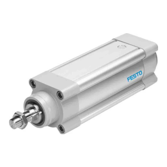
ESBF-BS/-LS
Electric cylinder
Operating instructions
8155148
2021-04d
[8155150]
Translation of the original instructions
© 2021 all rights reserved to Festo SE & Co. KG
1
Applicable Documents
All available documents for the product è www.festo.com/sp.
2
2.1
Safety instructions
– Observe labelling on the product.
– Prior to assembly, installation and maintenance work: Switch off power supply,
ensure that it is off and secure it against being switched back on.
– Store the product in a cool, dry, UV-protected and corrosion-protected environ-
ment. Ensure that storage times are kept to a minimum.
– Observe tightening torques. Unless otherwise specified, the tolerance
is ± 20 %.
2.2
Intended Use
The electric cylinder is intended to be used for positioning payloads in combina-
tion with tools or as a drive when external guides are used.
2.3
Training of qualified personnel
Work on the product may only be carried out by qualified personnel who can
evaluate the work and detect dangers. The qualified personnel have knowledge
and experience in handling electric drives and axes.
3
– Contact the regional Festo contact if you have technical problems
è www.festo.com.
– Accessories and spare parts è www.festo.com/catalogue.
4
Product overview
4.1
Function
The electric cylinder converts the rotary motion of the mounted motor into a linear
motion of the non-rotating piston rod. The lead screw converts the torque of the
motor into a feed force. The linear movement of the piston rod is precisely guided
by the guide in the bearing cap. Sensors enable the monitoring of end positions,
reference position and intermediate position.
Lead screw ESBF-LS
– Low speeds
– Self-braking with de-energised motor (without
brake)
Tab. 1: Overview of Lead Screw
Festo SE & Co. KG
Ruiter Straße 82
73734 Esslingen
Deutschland
+49 711 347-0
www.festo.com
Ball screw drive ESBF-BS
– High speeds
– High forces
4.2
Product design
ESBF product design
3
4
2
1
Fig. 1: ESBF product design (example ESBF-BS)
1 Piston rod
2 Threaded hole for mounting
3 Bearing cap
4 Cylinder profile
5 Pressure compensation port
6 Drive cover
5
Transport and Storage
NOTICE
Unexpected and unbraked movement of components
• Secure moving components for transport.
Transport and Storage Conditions
– Take product weight into account è Technical data.
Weight > 25 kg: transport with a suitable hoist (cross-brace) or with two per-
sons.
– Take the product focus into consideration.
– Store and transport the product in its original packaging.
– Store product in a cool, dry, shaded and corrosion protected environment.
– Store product in ambient conditions without oils, greases and degreasing
vapours.
– Ensure short storage times.
6
6.1
Safety
WARNING
Risk of Injury due to Unexpected Movement of Components
For vertical or slanted mounting position: when power is off, moving parts can
travel or fall uncontrolled into the lower end position.
• Bring moving parts of the product into a safe end position or secure them
against falling.
6.2
Unpacking
1. Open packaging.
2. Remove all transport materials (e.g. foils, caps, cardboard boxes).
3. Remove the product from the packaging and place it on the mounting surface.
4. Dispose of packaging and transport materials.
6.3
Transverse load on the drive shaft
When mounting the motor and motor mounting kit, do not exceed the maximum
transverse load F
of the drive shaft (for example toothed belt tension when
R
mounting the parallel kit) è 12.2 Characteristic curves.
Axial kit EAMM-A
Tab. 2: Overview of motor mountings
Requirement
– Only loosen screws or threaded pins that are described in the directions in the
instruction manuals.
– Sufficient space for reaching and mounting the pressure compensation port
è Connecting pressure compensation (ESBF -...- S1 only).
1. Select the motor and motor mounting kit from
Festoè www.festo.com/catalogue.
If other motors are used: observe the critical limits for forces, torques and
velocities.
5
6
7
8
9
10
11
7 Drive shaft
8 Threaded hole for motor
mounting kit
9 Interface for sensor bracket
10 Interface for sensor rail
11 Interface for profile mounting
Parallel kit EAMM-U
Advertisement
Table of Contents

Related Manuals for Festo ESBF-BS Series


Summary of Contents for Festo ESBF-BS Series
- Page 1 5 Pressure compensation port 11 Interface for profile mounting Translation of the original instructions 6 Drive cover © 2021 all rights reserved to Festo SE & Co. KG Transport and Storage Applicable Documents NOTICE Unexpected and unbraked movement of components •...
- Page 2 2. Fasten motor mounting kit, observe instruction manual è www.festo.com/sp. 3. Fasten the motor without tension. Support large and heavy motors. Mounting the attachment component on the piston rod Connect motor cables only on completion of mounting. When mounting the attachment component, do not exceed the maximum torque Mounting the cylinder of the piston rod.
- Page 3 Torque on the Piston Rod – Prevention of contamination in the slots. During commissioning and operation, the piston rod may only be operated 1. Select accessories è www.festo.com/catalogue. without torque. 2. Mount the sensor (reference or query): If external torques occur, an external guide must be used.
- Page 4 Lubrication 10.2 Repair Lubrication Interval and Accessories – Observe the instructions for dismantling è 11 Disassembly. – Send the electric cylinder to the Festo repair service. Lubrication Lead screw Piston rod – Information about spare parts and accessories è www.festo.com/spareparts.
- Page 5 Additional information è www.festo.com/catalogue. Size ESBF-BS-32/40 Spindle pitch Size è Max. permissible forces on the drive shaft 12.2 Characteristic curves Spindle pitch Max. transverse load Fq 1100 1100 Design Electric cylinder with ball screw drive Max. permitted forces, torques and torsional backlash on the piston rod è...
- Page 6 Fig. 10: ESBF-BS-32, feed force F as a function of the feed speed v ESBF-BS-32-...-5P ESBF-BS-32-...-10P Fig. 5: ESBF, transverse load Fq as a function of piston rod length l ESBF-BS/LS-32 ESBF-BS-80/100 ESBF-BS/LS-40 ESBF-BS/LS-50/ESBF- Fig. 11: ESBF-BS-40, feed force F as a function of the feed speed v BS-63 ESBF-BS-40-...-5P ESBF-BS-40-...-16P...
- Page 7 Fig. 21: ESBF-BS-63, pressure force F as a function of the piston rod length l ESBF-BS-63-…-5P/10P ESBF-BS-63-…-25P Fig. 15: ESBF-BS-100, feed force F as a function of the feed speed v ESBF-BS-100-...-5P ESBF-BS-100-...-40P ESBF-BS-100-...-20P Fig. 22: ESBF-BS-80, pressure force F as a function of the piston rod length l ESBF-BS-80-…-5P/15P ESBF-BS-80-…-32P Fig.
- Page 8 Fig. 27: ESBF-BS-40, feed speed v as a function of the stroke l ESBF-BS-40-...-5P ESBF-BS-40-...-16P ESBF-BS-40-...-10P Fig. 28: ESBF-BS-50, feed speed v as a function of the stroke l ESBF-BS-50-...-5P ESBF-BS-50-...-20P ESBF-BS-50-...-10P ESBF-63 1000 1200 l [mm] Fig. 29: ESBF-BS-63, feed speed v as a function of the stroke l ESBF-BS-63-...-5P ESBF-BS-63-...-25P ESBF-BS-63-...-10P...
Need help?
Do you have a question about the ESBF-BS Series and is the answer not in the manual?
Questions and answers