Table of Contents
Advertisement
Available languages
Available languages
Advertisement
Chapters
Table of Contents

Related Manuals for Festo EasyPort USB D16A


Summary of Contents for Festo EasyPort USB D16A
- Page 1 EasyPort USB Manual CD-ROM included 721876 DEENESFR...
- Page 2 Eberhardt, Löffler Graphics: Schwarzenberger Layout: 11/2008 © Festo Didactic GmbH & Co. KG, 73770 Denkendorf, Germany, 2008 Internet: www.festo-didactic.com e-mail: did@de.festo.com The copying, distribution and utilization of this document as well as the communication of its contents to others without expressed authorization is prohibited.
-
Page 3: Table Of Contents
Aufbau von EasyPort USB ____________________________ 22 Bedienelemente ____________________________________ 24 Befestigen von EasyPort USB _________________________ 25 Verbinden von EasyPort USB mit PC und Prozess _________ 26 Einstellen der Adresse am EasyPort USB ________________ 28 © Festo Didactic GmbH & Co. KG „ 721876... - Page 4 OPC-Server EasyOPC Handbuch EasyPort USB Handbuch EasyVeep USB-Treiber für EasyPort EasyPort USB ActiveX Steuerelement Beispiele zur Ansteuerung Beispiel mit Excel Beispiel mit FluidSIM Beispiel mit InTouch Beispiel mit LabVIEW Beispiel mit VC6 © Festo Didactic GmbH & Co. KG „ 721876...
-
Page 5: Einleitung
PC läuft Steuern eines simulierten Prozessmodells mit einer realen SPS Regelung eines realen Prozesses, die Regelung läuft auf dem PC Aufnehmen und Auswerten von Messwerten aus einem realen Prozess © Festo Didactic GmbH & Co. KG „ 721876... - Page 6 In all diesen Anwendungen verbindet EasyPort USB die reale Welt mit der virtuellen Welt des PC. Das Prozessinterface EasyPort USB verfügt über je 16 digitale Ein- und Ausgänge sowie 4 analoge Ein- und 2 analoge Ausgänge. © Festo Didactic GmbH & Co. KG „ 721876...
- Page 7 PORT 2 Konfiguration mit 4 EasyPort USB Modulen Für den Austausch der Prozesssignale zwischen EasyPort USB und der PC-Software steht der OPC-Server EzOPC oder das ActiveX Steuerelement von EasyPort USB zur Verfügung. © Festo Didactic GmbH & Co. KG „ 721876...
- Page 8 Simulationsbox. Auch für die virtuelle Welt stehen Ihnen unterschiedliche Softwareprogramme zur Verfügung. Es sind Programme zur Steuerung Regelung Messwerterfassung Visualisierung. In diesen vorbereiteten Konfigurationen ist EasyPort USB sehr einfach zu nutzen. © Festo Didactic GmbH & Co. KG „ 721876...
- Page 9 ‟ MPS PA digital ‟ MPS PA ‟ MPS PA ‟ MPS ‟ SPS EduTrainer ‟ TP210 ‟ TP210 ‟ TP301 ‟ SPS Board ‟ TP610 ‟ TP610 Beispielanwendungen zu EasyPort USB © Festo Didactic GmbH & Co. KG „ 721876...
- Page 10 Sie die Befehle für EasyPort USB mit einem einfachen Terminal- Programm ausführen, wie Sie anhand einer Demo-Anwendung die Methoden des ActiveX Steuerelementes nutzen, wo Sie weitere Beispiele für das Einbinden von EasyPort USB in eigene Anwendungen finden. © Festo Didactic GmbH & Co. KG „ 721876...
-
Page 11: Wichtige Hinweise
USB sicherheitsgerecht zu betreiben. Insbesondere die Sicherheitshinweise sind von allen Personen zu beachten, die mit EasyPort USB arbeiten. Darüber hinaus sind die für den Einsatzort geltenden Regeln und Vorschriften zur Unfallverhütung zu beachten. © Festo Didactic GmbH & Co. KG „ 721876... -
Page 12: Verpflichtung Des Betreibers
Sachwerten entstehen. Das Prozessinterface EasyPort USB ist nur zu benutzen: für die bestimmungsgemäße Verwendung und in sicherheitstechnisch einwandfreiem Zustand. Störungen, die die Sicherheit beeinträchtigen können, sind umgehend zu beseitigen! © Festo Didactic GmbH & Co. KG „ 721876... -
Page 13: Gewährleistung Und Haftung
Unsachgemäß durchgeführte Reparaturen Katastrophenfälle durch Fremdkörpereinwirkung und höhere Gewalt. Festo Didactic schließt hiermit jegliche Haftung für Schäden des Auszubildenden, des Ausbildungsunternehmens und/oder sonstiger Dritter aus, die bei Gebrauch/Einsatz des EasyPort USB außerhalb einer reinen Ausbildungssituation auftreten; es sei denn Festo Didactic hat solche Schäden vorsätzlich oder grob fahrlässig verursacht. -
Page 14: Sicherheitshinweise
Verwenden Sie ausschließlich die von Festo Didactic empfohlenen Verbindungskabel für die elektrischen Verbindungen zwischen dem Prozessinterface EasyPort USB und dem Prozess. Beachten Sie auch die Angaben der Datenblätter zu den angeschlossenen Geräten, insbesondere auch alle Hinweise zur Sicherheit! © Festo Didactic GmbH & Co. KG „ 721876... -
Page 15: Technische Daten
2 Eingänge als schneller Zähler nutzbar, = 20 kHz / U = 5…24 VDC Kommunikations- RS232, galvanisch getrennt schnittstellen USB2.0, galvanisch getrennt Protokoll ASCII, 115,2 kBaud,8,N,1 Technische Daten EasyPort USB allgemein © Festo Didactic GmbH & Co. KG „ 721876... -
Page 16: Syslink-Schnittstelle Für Digitale Daten
Steckbuchse 24-polig nach IEEE 488 verdrahtet. Zusätzlich kann der SysLink-Schnittstelle Eingang 0 bei Port 1 und Port 2 als schneller Zähleingang genutzt für digitale Daten werden. Die Zähleingänge können mit Spannungspegeln von 5…24 VDC betrieben werden. © Festo Didactic GmbH & Co. KG „ 721876... - Page 17 INPUT 5 INPUT 6 INPUT 6 INPUT 7 INPUT 7 0 VDC 11/12/ 0 VDC 11/12/ 23/24 23/24 24 VDC 9/10/ 24 VDC 9/10/ 21/22 21/22 Technische Daten SysLink-Schnittstelle für digitale Signale © Festo Didactic GmbH & Co. KG „ 721876...
-
Page 18: Sub D Buchse Für Analoge Daten
Anschluss Sub D 15-polig, Buchse Port 3 OUTPUT 0 OUTPUT 1 (frei) (frei) INPUT 1 INPUT 2 (frei) (frei) +10 VDC REF (frei) (frei) INPUT 3 INPUT 4 Technische Daten Sub D-Buchse für analoge Signale © Festo Didactic GmbH & Co. KG „ 721876... -
Page 19: Datenschnittstellen Zum Pc
Adressen der EasyPort-Module unterschiedlich sind. Erlaubt sind die Adressen 1 bis 4. Für den Anschluss von EasyPort USB an den USB-Port des PC bzw. eines Hub verwenden Sie beigelegtes USB-Kabel A-B. © Festo Didactic GmbH & Co. KG „ 721876... -
Page 20: Stromversorgung
Sie kann entweder über die Ports 1 und 2 oder über zwei getrennte Stromversorgung Schraubklemmen, die an der Rückseite von EasyPort USB angebracht sind, erfolgen. Zwei Kabel mit 4 mm Sicherheitsstecker sind beigelegt. © Festo Didactic GmbH & Co. KG „ 721876... -
Page 21: Transport/Auspacken/Lieferumfang
Prozesssimulation EasyVeep, Software EzOPC, USB-Treiber, ActiveX- Steuerelement als Programmierschnittstelle zu EasyPort USB mit Online-Hilfe und Programmbeispielen Handbuch EasyPort USB Den Lieferumfang entsprechend dem Lieferschein und der Bestellung überprüfen. Mögliche Abweichungen sind unverzüglich Festo Didactic zu melden. © Festo Didactic GmbH & Co. KG „ 721876... -
Page 22: Aufbau Und Funktion
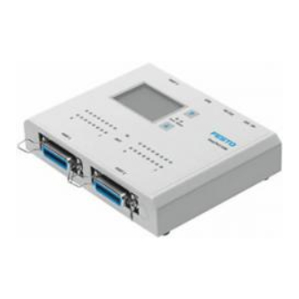
(9) LEDs für die Zustandsanzeige der digitalen Ausgänge (gelb) (10) LEDs für die Zustandsanzeige der digitalen Eingänge (grün) (11) LCD Anzeige für analoge Signale und Adresse des EasyPort Aufbau EasyPort USB © Festo Didactic GmbH & Co. KG „ 721876... - Page 23 Zwei Tasten zum Einstellen des Analogkanals, zum Auswählen der physikalischen Einheit des Analogwertes und zum Einstellen der Adresse des EasyPort USB Nicht im Lieferumfang enthalten sind Netzgerät 24 VDC Anschlusskabel für die SysLink-Schnittstelle Anschlusskabel für Sub D Buchse © Festo Didactic GmbH & Co. KG „ 721876...
-
Page 24: Bedienelemente
Zustand nach Einschalten, das EasyPort USB Modul kommuniziert noch nicht ‟ Blinken pulsierend: EasyPort USB Modul ist adressiert. Die Adresse wird im Abstand von 2 s durch eine Anzahl kurzer Leuchtsignale angezeigt. © Festo Didactic GmbH & Co. KG „ 721876... -
Page 25: Befestigen Von Easyport Usb
Durch den Adapter mit der Bestell-Nr. 549806 kann das EasyPort USB Modul direkt auf einer Profilplatte befestigt werden. Befestigen von Der Adapter wird über drei M4 Schrauben am Boden des EasyPort USB EasyPort USB Moduls befestigt. © Festo Didactic GmbH & Co. KG „ 721876... -
Page 26: Verbinden Von Easyport Usb Mit Pc Und Prozess
Verbinden von EasyPort USB mit PC und Prozess Für die Verbindung von EasyPort USB mit dem realen Steuerungsprozess stehen unterschiedliche E/A-Datenkabel zur Verfügung. Welches E/A-Kabel Sie benötigen, hängt von der steuerungstechnischen Anwendung ab. © Festo Didactic GmbH & Co. KG „ 721876... - Page 27 E/A-Kabel einsetzen müssen. Um die digitalen E/A-Kabel besser unterscheiden zu können, besitzt das gekreuzte digitale E/A-Kabel eine schwarze Kennung am Kabelende. Kabel für das Verbinden von EasyPort USB mit PC und Prozess © Festo Didactic GmbH & Co. KG „ 721876...
-
Page 28: Einstellen Der Adresse Am Easyport Usb
Werkseitig voreingestellt ist die Adresse 1 für jedes EasyPort USB Prozessinterface. PORT 3 RS 232 24V 0V EasyPort USB Error Status PORT 1 PORT 2 LCD Display von EasyPort USB mit Anzeige der Adresse © Festo Didactic GmbH & Co. KG „ 721876... -
Page 29: Inbetriebnahme
‟ Stellen Sie mit den Pfeiltasten eine Adresse von 1 bis 4 ein. ‟ Verlassen Sie den Adressmodus durch gleichzeitiges Drücken der beiden Pfeiltasten. 5. Verbinden Sie den PC mit dem EasyPort USB. Verwenden Sie dazu das beigelegte USB-Kabel. © Festo Didactic GmbH & Co. KG „ 721876... - Page 30 Erst wenn Ihnen der unten abgebildete Dialog angezeigt wird, installieren Sie die USB-Treiber von der mitgelieferten CD-ROM. Legen Sie dazu die EasyPort CD-ROM ein. Sobald das CD-ROM Laufwerk betriebsbereit ist, klicken Sie auf die Schaltfläche Weiter. © Festo Didactic GmbH & Co. KG „ 721876...
- Page 31 6. Inbetriebnahme 7. Die erforderliche Softwarekomponente wird gesucht. Nach erfolgreicher Installation klicken Sie auf die Schaltfläche Fertig stellen. © Festo Didactic GmbH & Co. KG „ 721876...
- Page 32 Installieren Sie auch hier die Software nicht über einen Windows Update, sondern immer von der mitgelieferten EasyPort CD-ROM. Wird Ihnen der unten abgebildete Dialog angezeigt und ist die EasyPort CD-ROM eingelegt, dann klicken Sie auf die Schalfläche Weiter. © Festo Didactic GmbH & Co. KG „ 721876...
- Page 33 Ihrem PC installiert. Damit können Sie EasyPort USB in Verbindung mit Ihrem PC nutzen. 11. Mit der EasyPort Demo-Anwendung können Sie auf einfache Weise eine Verbindung zu EasyPort USB herstellen und EasyPort USB initialisieren. © Festo Didactic GmbH & Co. KG „ 721876...
- Page 34 EasyPort CD-ROM wird die Demo-Anwendung auf Ihren PC kopiert. 13. Klicken Sie auf die Schaltfläche Connect, um die Verbindung zwischen der EasyPort Demo-Anwendung und dem EasyPort USB herzustellen. Gleichzeitig wird das EasyPort USB Modul initialisiert. © Festo Didactic GmbH & Co. KG „ 721876...
- Page 35 Wenn der PC, zu dem die USB-Verbindung von EasyPort besteht, ausgeschaltet wird, sollte auch das USB-Kabel abgezogen werden. Erst nach Neustart des PC und des Softwareprogramms, das mit EasyPort USB kommunizieren soll, das USB-Kabel wieder einstecken. © Festo Didactic GmbH & Co. KG „ 721876...
-
Page 36: Softwareschnittstellen Zu Easyport Usb
Programm direkt angesprochen werden ActiveX Steuerelement beschreibt die Zugriffsfunktionen und ist damit die Programmierschnittstelle zu EasyPort USB EzOPC EzOPC ist ein OPC-Server und stellt die Kommunikationsverbindungen für vorbereitete Anwendungen mit Festo Didactic Produkten her © Festo Didactic GmbH & Co. KG „ 721876... - Page 37 Visual Basic und C++. Aber auch Programme zur Messwerterfassung und ‟Auswertung wie zum Beispiel LabVIEW oder Visualisierungssysteme bieten diese Schnittstelle an. Wenn Sie EasyPort USB zusammen mit anderen Festo Didactic Produkten einsetzen, können Sie auf einfache Weise die Kommunikation zwischen den Kommunikationspartnern erstellen. Sie nutzen dazu den OPC-Server EzOPC, ein Programm mit einer grafischen Bedienoberfläche.
-
Page 38: Kommunikation Über Ezopc
OPC steht für open connectivity via open standards und ist eine etablierte Standardschnittstelle in der Automatisierungstechnik. Sie sorgt für einen effizienten Datenfluss zwischen Windows-Applikationen und Automatisierungsgeräten. Softwareschnittstelle: EzOPC © Festo Didactic GmbH & Co. KG „ 721876... - Page 39 Datenaustausch geschieht über EasyPort und EzOPC. Die virtuelle Steuerung ist das „Herz“ des EzOPC. Sie stellt das virtuelle Klemmbrett dar, das den Signalbereich des einen Kommunikationspartners mit dem Signalbereich des anderen Kommunikationspartners verbindet. © Festo Didactic GmbH & Co. KG „ 721876...
- Page 40 Wenn kein automatischer Start ausgeführt wird, dann starten Sie das Programm Start.exe auf der CD-ROM. 3. Es erscheint der Starbildschirm. Wählen Sie die Sprache aus, in der Sie das Softwareprogramm EzOPC installieren wollen. Klicken Sie auf die entsprechende Schaltfläche. © Festo Didactic GmbH & Co. KG „ 721876...
- Page 41 Programmbeispiele angeboten. Klicken Sie unter Anwendungen auf Installieren von OPC-Server EzOPC. 5. Für EzOPC wird standardmäßig die Programmgruppe EzOPC im Startmenü angelegt. Dort finden Sie auch die zugehörige Online- Hilfe zu EzOPC. © Festo Didactic GmbH & Co. KG „ 721876...
-
Page 42: Activex Steuerelement Zu Easyport Usb
HTML. Aber auch Systeme zur Messwerterfassung wie zum Beispiel LabVIEW oder Visualiserungssysteme unterstützen die COM- Schnittstelle. Softwareschnittstelle: ActiveX Steuerelement Das ActiveX Steuerelement und seine Methoden sind ausführlich beschrieben in der Online-Hilfe. © Festo Didactic GmbH & Co. KG „ 721876... -
Page 43: Installation Des Activex Steuerelementes
Klicken Sie auf Installieren von EasyPort ActiveX Steuerelement. 5. Für das EasyPort ActiveX Steuerelement wird standardmäßig die Programmgruppe EasyPort im Startmenü angelegt. Dort finden Sie auch die zugehörige Online-Hilfe und eine Demo-Anwendung zum ActiveX Steuerelement. © Festo Didactic GmbH & Co. KG „ 721876... -
Page 44: Beispiel: Easyport Demo-Anwendung
Mit der Installation des ActiveX Steuerelementes von EasyPort wird auch die Demo-Anwendung auf Ihren PC kopiert. Sie finden die Demo-Anwendung im Startmenü in der Programmgruppe EasyPort unter dem Eintrag EasyPort Demo-Anwendung. EasyPort Demo-Anwendung © Festo Didactic GmbH & Co. KG „ 721876... - Page 45 Meldung. Führen Sie daraufhin die Installation der USB-Treiber durch. Sie benötigen dazu die EasyPort CD-ROM. 4. Stellen Sie sicher, dass das ActiveX Steuerelement zu EasyPort USB auf Ihrem PC installiert ist. © Festo Didactic GmbH & Co. KG „ 721876...
- Page 46 Aufruf der Methode ein. 6. Bevor Sie Befehle ausführen können, müssen Sie die Verbindung zwischen der EasyPort Demo-Anwendung und dem EasyPort USB Modul herstellen. Klicken Sie dazu auf die Schaltfläche Connect. © Festo Didactic GmbH & Co. KG „ 721876...
- Page 47 Ausgangswort ist voreingestellt, Sie können den Wert unverändert übernehmen. Klicken Sie dann auf die Schaltfläche SetOutputWord. Die LED der Ausgänge 0 bis 3 am Port 1 von Ihrem EasyPort USB leuchten gelb. © Festo Didactic GmbH & Co. KG „ 721876...
- Page 48 GetOutputWord. Der Wert des Ausgangswortes 0 beträgt 15 und wird links neben der Methode angezeigt. 11. Wenn Sie die Kommunikation zwischen der EasyPort Demo- Anwendung und dem EasyPort USB direkt verfolgen wollen, dann klicken Sie auf die Schaltfläche ShowDebugWnd. © Festo Didactic GmbH & Co. KG „ 721876...
- Page 49 8. ActiveX Steuerelement zu EasyPort USB 12. Es wird das Fenster Trace Window angezeigt. In diesem Fenster werden die Befehle an das EasyPort USB Modul und die Antwort des EasyPort auf den Befehl protokolliert. © Festo Didactic GmbH & Co. KG „ 721876...
- Page 50 14. Wollen Sie die Verbindung zu EasyPort USB beenden, dann klicken Sie auf die Schaltfläche Disconnect. Hinweis Mit der EasyPort Demo-Anwendung können Sie schnell und komfortabel die Verbindung zu einem EasyPort USB herstellen und testen. © Festo Didactic GmbH & Co. KG „ 721876...
-
Page 51: Befehlsinterpreter Von Easyport Usb
Jeder Befehlt besteht aus einem Befehlsbuchstaben (Operator) und einer Betriebsmitteladresse (Operand). Die Betriebsmitteladresse adressiert das gewünschte Signal. Für einige ältere Befehle ist die Angabe der Adresse des EasyPort USB Moduls erforderlich, bei jüngeren Befehlen entfällt sie. © Festo Didactic GmbH & Co. KG „ 721876... -
Page 52: Befehlsstruktur
• Byte (B) • Wort (W) Ein Wort besteht aus Byte 0 und 1 und enthält die Bitadressen 0 bis 15. Byte 1 Byte 0 (Port 2) (Port 1) Wort 0 © Festo Didactic GmbH & Co. KG • 721876... - Page 53 Modul 2 auf 1 Modify-Befehlen muss ein Datenwert mitgegeben werden. Der Datenwert schließt sich an die Betriebsmitteladresse mit einem Gleichheitszeichen an. Beachten Sie: Adresszahlen und Datenwerte müssen immer hexadezimal eingegeben werden © Festo Didactic GmbH & Co. KG „ 721876...
-
Page 54: Übertragungsebene
Schreibweise wie bei einem Modify-Befehl angefügt. Nachfolgend sind einige Beispiele für Befehle und Antworten auf diese Befehle aufgeführt. Mit dargestellt in diesen Beispielen ist auch das Carriage Return Zeichen <CR>. © Festo Didactic GmbH & Co. KG „ 721876... - Page 55 MAW1.0=201<CR> AW1.0=201<CR> Datenwert ist 201 hexadezimal bzw. 513 dezimal MAB2.0.0=73<CR> AB2.0.0=73<CR> Datenwert ist 73 hexadezimal bzw. 115 dezimal MA3.0.A=1<CR> A3.0.A=1<CR> Ausgangsbit 10 wird auf 1 gesetzt. Beispiele für Modify- und Display-Befehle © Festo Didactic GmbH & Co. KG „ 721876...
-
Page 56: Befehle Zur Initialisierung Und Diagnose
Antwort Beschreibung setup0 setup1 Das EasyPort USB Modul gibt als Adresse die Adresse 1 zurück. V=2.10 Versionsnummer ausgeben Das EasyPort USB Modul gibt mit V=2.10 seine Version zurück. Initialisierung und Diagnose © Festo Didactic GmbH & Co. KG „ 721876... - Page 57 Das Easyport USB Modul ist korrekt initialisiert, als Ein- und Ausgangs- spannung sind 0…10 V eingestellt, die Taste ist gedrückt und die Anzeige des Displays ist auf normale Anzeige eingestellt. Initialisierung und Diagnose (Fortsetzung) © Festo Didactic GmbH & Co. KG „ 721876...
-
Page 58: Befehle Für Digitale Signale
Bit 0, Bit 1 und Bit 2 werden gesetzt. niederwertig: Byte 0 (Port 1) höherwertig: Byte 1 (Port 2) W (Wort) MAW1.0=101 Modify Ausgangswort 0 in EasyPort USB Modul 1 auf 101 hexadezimal bzw. 257 dezimal. © Festo Didactic GmbH & Co. KG „ 721876... - Page 59 Display Ausgangsbyte 0 von Wort 0 in EasyPort USB Modul 4 DAB2.0.1 Display Ausgangsbyte 1 von Wort 0 in Modul 2 W (Wort) DAW3.0 Display Ausgangswort 0 in EasyPort USB Modul 3 © Festo Didactic GmbH & Co. KG „ 721876...
- Page 60 EasyPort USB Modul 2, dann wird das komplette Eingangswort nach 10 ms automatisch an den PC gemeldet. MT2=00 Der Ereignismodus für EasyPort USB Modul 2 wird beendet. Eingangssignale werden nur noch auf Anforderung an den PC gemeldet. © Festo Didactic GmbH & Co. KG „ 721876...
-
Page 61: Befehle Für Analoge Signale
Zahlenbereich ist immer der Bereich von 0x0000 bis 0x7FFF (32767 dezimal). 10 V 0x0000 0x3FFF 0x7FFF Zuordnung analog-digital für Spannungsbereich 0…10 V -10 V +10 V 0x0000 0x3FFF 0x 7FFF Zuordnung analog-digital für den Spannungsbereich ‟10…+10 V © Festo Didactic GmbH & Co. KG „ 721876... - Page 62 Eingänge auf ‟10…+10 V gesetzt. Beispiel MRE2=1 Am EasyPort USB Modul mit der Adresse 2 den Spannungsbereich für die analogen Eingänge auf ‟10…+10 V setzen. Umschalten des Messbereichs für die analogen Eingänge © Festo Didactic GmbH & Co. KG „ 721876...
- Page 63 Einlesen eines analogen Eingangs wird der Befehl DEW mit Angabe der Adresse des EasyPort USB Moduls und der Kanalnummer verwendet. Aufgrund des Datenformats der analogen Eingänge ist der Wertebereich von 0x0000 bis 0x7FF8 (32760 dezimal) möglich. 12-Bit-Analogeingang Datenformat der analogen Eingänge © Festo Didactic GmbH & Co. KG „ 721876...
- Page 64 Werte am Eingangskanal 2 eingelesen. DEW<n>.8 EW<n>.8=xxxx Eingangskanal 3 einlesen mit xxxx = 0000…7FF8 Am EasyPort USB Modul mit der Adresse <n>, <n>=1…4, werden die Werte am Eingangskanal 3 eingelesen. Einlesen der analogen Eingangssignale © Festo Didactic GmbH & Co. KG „ 721876...
- Page 65 Schreiben eines Spannungswertes wird der Befehl MAW mit Angabe der Adresse des EasyPort USB Moduls, der Kanalnummer und des Wertes verwendet. Der Wertebereich für die analogen Ausgänge beträgt auch hier 0x0000 bis 0x7FF8 (32760 dezimal). 12-Bit-Analogausgang Datenformat der analogen Ausgänge © Festo Didactic GmbH & Co. KG „ 721876...
- Page 66 üblicherweise mit den Pfeiltasten direkt am EasyPort USB aus. Mit einem Befehl des Befehlsinterpreters können Sie die eingestellte Kanalwahl vorübergehend vom PC aus unterdrücken und auf einen anderen analogen Kanal umstellen. Sie verwenden dazu den Befehl MF. © Festo Didactic GmbH & Co. KG „ 721876...
- Page 67 Am LCD Display des EasyPort USB Moduls mit der Adresse <n>, <n>=1…4, werden wieder die Messwerte des analogen Kanals angezeigt, der mit den Pfeiltasten direkt am EasyPort USB eingestellt wird. Forcieren eines Analogkanals zur Anzeige am LCD Display © Festo Didactic GmbH & Co. KG „ 721876...
-
Page 68: Befehle Zum Messen Von Analogen Signalen
Alle analogen Eingangskanäle deaktivieren Am EasyPort USB Modul mit der Adresse <n>, <n>=1…4, alle analogen Eingangskanäle deaktivieren. Ein automatisches Ausgeben der Eingangswerte ist dann nicht mehr möglich. Aktivieren von analogen Eingangskanälen © Festo Didactic GmbH & Co. KG „ 721876... - Page 69 Bedeutung. Deshalb kann jedem Analogkanal eine eigene physikalische Einheit zugeordnet werden. Wird der Analogkanal zur Anzeige am LCD Display ausgewählt, dann wird die vom PC aus zugeordnete physikalische Einheit dargestellt. © Festo Didactic GmbH & Co. KG „ 721876...
- Page 70 Am LCD Display des EasyPort USB Moduls mit der Adresse <n>, <n>=1…4, wird für den analogen Eingangskanal 3 die Einheit xx angezeigt. Zuordnen einer physikalischen Einheit zur Darstellung auf dem LCD Display © Festo Didactic GmbH & Co. KG „ 721876...
- Page 71 Analogkanal anliegt, nicht verändert. Der Verstärkungsfaktor wirkt nur auf die Anzeige der Werte auf dem LCD Display. Für jede physikalische Einheit ist der Verstärkungsfaktor voreingestellt. Physikalische Einheit Voreinstellung Verstärkungsfaktor 10.0 l/min © Festo Didactic GmbH & Co. KG „ 721876...
- Page 72 Die Einheit bar wird am LCD Display angezeigt. MG1.1=6.00 Der am LCD Display von EasyPort USB Modul 1 angezeigte Messwert mit der Einheit bar wird mit dem Faktor 6.00 multipliziert. © Festo Didactic GmbH & Co. KG „ 721876...
- Page 73 Der am LCD Display des EasyPort USB Moduls mit der Adresse <n>, <n>=1…4, dargestellte Messwert mit der Einheit C wird mit dem Faktor x.xx multipliziert. Zuweisen eines Verstärkungsfaktors zur Darstellung auf dem LCD Display © Festo Didactic GmbH & Co. KG „ 721876...
-
Page 74: Befehle Für Schnellen Zähler
MC<n>.<m>=0 C<n>.<m>=0 Schnellen Zähler deaktivieren Für das EasyPort USB Modul mit der Adresse <n>, <n>=1…4, wird der schnelle Zähler mit der Nummer <m>, <m>=0,1 deaktiviert. Aktivieren und Deaktivieren des schnellen Zählers © Festo Didactic GmbH & Co. KG „ 721876... -
Page 75: Beispiel: Aufbau Einer Verbindung Zu Easyport Usb
2. Serielle Schnittstelle für den USB-Anschluss ermitteln. 3. Terminalprogramm starten. 4. Einstellungen zur seriellen Schnittstelle eintragen. 5. Befehle an EasyPort senden. Der Aufbau einer Verbindung ist exemplarisch für das Terminal- Programm HyperTerminal von Windows gezeigt. © Festo Didactic GmbH & Co. KG „ 721876... - Page 76 3. Starten Sie im Startmenü unter Systemeinstellungen den Eintrag Systemsteuerung. 4. Wählen Sie den Eintrag System aus. 5. Es öffnet sich das Fenster Systemeigenschaften. Klicken Sie im Register Hardware auf die Schaltfläche Geräte- Manager. © Festo Didactic GmbH & Co. KG „ 721876...
- Page 77 6. Unter dem Eintrag Ports (COM & LPT) entnehmen Sie, dass als serielle Schnittstelle für den USB-Anschluss COM5 verwendet wird. 7. Starten Sie nun das Programm HyperTerminal. Sie finden HyperTerminal unter Programme\Zubehör\Communications. © Festo Didactic GmbH & Co. KG „ 721876...
- Page 78 8. Als erstes legen Sie eine neue Verbindung an. Bezeichnen Sie die Verbindung mit EasyPort USB. 9. Im Folgenden werden die Einstellungen für die neue Verbindung abgefragt. Als Schnittstelle tragen Sie im Fenster Connect To die zuvor ermittelte Schnittstelle COM5 ein. © Festo Didactic GmbH & Co. KG „ 721876...
- Page 79 9. Befehlsinterpreter von EasyPort USB 10. Die erforderlichen Einstellungen für die serielle Datenübertragung über die COM-Schnittstelle finden Sie in diesem Handbuch. Korrekt sind folgende Angaben: © Festo Didactic GmbH & Co. KG „ 721876...
- Page 80 9. Befehlsinterpreter von EasyPort USB 11. Die weiteren Eigenschaften tragen Sie im Fenster Eigenschaften von EasyPort USB ein. Sie finden den Dialog im Menü File unter Properties. Klicken Sie auf das Register Settings. © Festo Didactic GmbH & Co. KG „ 721876...
- Page 81 9. Befehlsinterpreter von EasyPort USB 12. Im Register Settings klicken Sie auf die Schaltfläche ASCII Setup. © Festo Didactic GmbH & Co. KG „ 721876...
- Page 82 9. Befehlsinterpreter von EasyPort USB 13. Im Fenster ASCII Setup wählen Sie folgende Einstellungen: 14. Damit sind alle erforderlichen Daten zur Kommunikationsverbindung eingetragen. Sie können nun mit EasyPort USB kommunizieren. © Festo Didactic GmbH & Co. KG „ 721876...
- Page 83 Befehle schließen Sie mit der ENTER-Taste ab. 16. Als Antwort erhalten Sie vom EasyPort USB Modul die Zeichenkette setup1. Das bedeutet: am EasyPort USB Modul ist die Adresse 1 eingestellt. Der Cursor springt auf die nächste Zeile. © Festo Didactic GmbH & Co. KG „ 721876...
- Page 84 17. Sie können nun weitere Befehle an das EasyPort USB Modul senden und zum Beispiel den Status abfragen. Dazu senden Sie den Befehl 18. Die Antwort S=02 zeigt Ihnen, dass das EasyPort USB Modul korrekt initialisiert wurde. © Festo Didactic GmbH & Co. KG „ 721876...
- Page 85 Eingänge den Wert 3 zurück. Es sind also die Eingänge 0 und 1 von Port 1 gesetzt. 21. Wenn Sie die Kommunikationsverbindung zwischen dem Programm HyperTerminal und EasyPort USB beenden wollen, dann aktivieren Sie den Eintrag Disconnect im Menü Call. © Festo Didactic GmbH & Co. KG „ 721876...
-
Page 86: Erstellen Eigener Anwendungen
ActiveX Steuerelementes für Sie vorbereitet. Die Beispiele zeigen exemplarisch, wie Sie das ActiveX Steuerelement in Excel, LabVIEW, InTouch oder auch FluidSIM einbinden. Sobald Sie die Beispiele installiert haben, finden Sie auch diese im Startmenü in der Programmgruppe EasyPort. © Festo Didactic GmbH & Co. KG „ 721876... - Page 87 Setting the address at the EasyPort USB _______________ 112 Commissioning ____________________________________ 113 Software interfaces to EasyPort USB __________________ 120 Overview: communication with EasyPort USB ___________ 120 Communication via EzOPC ___________________________ 122 © Festo Didactic GmbH & Co. KG „ 721876...
- Page 88 USB drivers for EasyPort EasyPort USB ActiveX control Control examples ‟ Example with Excel ® ‟ Example with FluidSIM ‟ Example with InTouch ‟ Example with LabVIEW ‟ Example with VC6 © Festo Didactic GmbH & Co. KG „ 721876...
-
Page 89: Introduction
Control an actual control process with a controller which runs on a PC Control a simulated process model with an actual PLC Regulate an actual process from a PC Record and evaluate measured values from an actual process © Festo Didactic GmbH & Co. KG „ 721876... - Page 90 With all of these applications, EasyPort USB connects the actual world to the virtual PC world. The EasyPort USB process interface is equipped with 16 digital inputs and outputs, as well as 4 analogue inputs and 2 analogue outputs. © Festo Didactic GmbH & Co. KG „ 721876...
- Page 91 Configuration with 4 EasyPort USB modules The OPC server EzOPC, or EasyPort USB ActiveX control, can be used to exchange process signals between the EasyPort USB and the PC software. © Festo Didactic GmbH & Co. KG „ 721876...
- Page 92 Various software programs are also available for the virtual world. Programs are available for: Control Regulation Measured value recording Visualisation EasyPort USB is very easy to use in these preparatory configurations. © Festo Didactic GmbH & Co. KG „ 721876...
- Page 93 ‟ MPS PA ‟ SPS EduTrainer ‟ MPS PA digital/analogue ‟ MPS ‟ PLC board ‟ TP210 ‟ MPS PA ‟ TP301 ‟ TP610 ‟ TP210 ‟ TP610 Sample applications for EasyPort USB © Festo Didactic GmbH & Co. KG „ 721876...
- Page 94 How to execute commands for EasyPort USB with a simple terminal program How to make use of ActiveX control methods with the help of a demo application Where to find additional examples for incorporating EasyPort USB into your own application. © Festo Didactic GmbH & Co. KG „ 721876...
-
Page 95: Important Instructions
In particular the safety precautions must be adhered to by all persons who work with EasyPort USB. In addition, all pertinent accident prevention rules and regulations, which are applicable at the respective location of use, must be adhered to. © Festo Didactic GmbH & Co. KG „ 721876... -
Page 96: Obligations Of The Operating Company
The EasyPort USB process interface may only be used: For the intended purpose When its safety functions are in perfect condition Faults which may impair safety must be eliminated immediately! © Festo Didactic GmbH & Co. KG „ 721876... -
Page 97: Guarantee And Liability
Improperly executed repairs Disasters resulting from the influence of foreign bodies and acts of God Festo Didactic hereby excludes any and all liability for damages suffered by trainees, the training company and/or any third parties, which occur during use of EasyPort USB in situations which serve any purpose other... -
Page 98: Safety Precautions
EasyPort USB. Use EasyPort USB only in systems that automatically change to a safe state when the power is switched off. Use connecting cables recommended by Festo Didactic only for electrical connections between the EasyPort USB process interface and the process. -
Page 99: Technical Data
= 20 kHz/U = 5 to 24 V DC Communication RS 232, electrically isolated, interfaces USB 2.0, electrically isolated Protocol ASCII, 115.2 kBaud, 8, N, 1 Technical data for EasyPort USB, general © Festo Didactic GmbH & Co. KG „ 721876... -
Page 100: Syslink Interface For Digital Data
0 at ports 1 and 2 can be used as high-speed counter for digital data inputs. The counter inputs can be operated with voltage levels ranging from 5 to 24 V DC. © Festo Didactic GmbH & Co. KG „ 721876... - Page 101 INPUT 7 INPUT 7 0 V DC 11/12/ 0 V DC 11/12/ 23/24 23/24 24 V DC 9/10/ 24 V DC 9/10/ 21/22 21/22 Technical data, SysLink interface for digital signals © Festo Didactic GmbH & Co. KG „ 721876...
-
Page 102: Sub-D Socket For Analogue Data
Port 3 OUTPUT 0 OUTPUT 1 (unused) (unused) INPUT 1 INPUT 2 (unused) (unused) +10 V DC ref. (unused) (unused) INPUT 3 INPUT 4 Technical data, Sub-D socket for analogue signals © Festo Didactic GmbH & Co. KG „ 721876... -
Page 103: Data Interfaces To The Pc
In this case, make sure that each EasyPort module has a different address. Addresses 1 through 4 are permissible. Use the included USB A-B cable to connect the EasyPort USB to the USB port at the PC, or to a USB hub. © Festo Didactic GmbH & Co. KG „ 721876... -
Page 104: Power Supply
1 and 2, or via two isolated screw terminals which are Power supply located on the back of the EasyPort USB. Two cables with 4 mm safety plugs are included. © Festo Didactic GmbH & Co. KG „ 721876... -
Page 105: Transport, Unpacking, Scope Of Delivery
Transport The EasyPort USB process interface is shipped in a carton. The carton must be secured against drops and falling. The freight forwarder and Festo Didactic must be notified immediately of any damage during transport. Unpacking Inspect the EasyPort USB process interface for possible damage after unpacking. -
Page 106: Layout And Function
(9) LEDs for indicating the status of the digital outputs (yellow) (10) LEDs for indicating the status of the digital inputs (green) (11) LCD panel for EasyPort analogue signals and addresses EasyPort USB layout © Festo Didactic GmbH & Co. KG „ 721876... - Page 107 EasyPort USB Not included in scope of delivery: 24 V DC power supply unit Connecting cable for SysLink interface Connecting cable for Sub-D socket © Festo Didactic GmbH & Co. KG „ 721876...
-
Page 108: Control Elements
Status immediately after start-up, the EasyPort USB module has not yet started communicating. ‟ Pulsating flashing: The EasyPort USB module has been addressed. The address is indicated every 2 seconds by a series of briefly flashing light signals. © Festo Didactic GmbH & Co. KG „ 721876... -
Page 109: Mounting The Easyport Usb
The EasyPort USB module can be mounted directly on a profile plate; the adapter is available under order number 549806. Mounting the The adapter is secured to the bottom of the EasyPort USB module with EasyPort USB three M4 screws. © Festo Didactic GmbH & Co. KG „ 721876... -
Page 110: Connecting The Easyport Usb To The Pc And The Process
Connecting the EasyPort USB to the PC and the process Various I/O data cables are available for connecting the EasyPort USB to the actual control process. Which I/O cable you will need depends on the control application. © Festo Didactic GmbH & Co. KG „ 721876... - Page 111 The digital crossover cable has a black mark on the end to make it easier to differentiate between the digital I/O cables. Cables for connecting EasyPort USB to the PC and the process © Festo Didactic GmbH & Co. KG „ 721876...
-
Page 112: Setting The Address At The Easyport Usb
All EasyPort USB process interfaces are set to a default address of 1 at the factory. PORT 3 24V 0V RS 232 EasyPort USB Error Status PORT 1 PORT 2 LCD panel at EasyPort USB with address display © Festo Didactic GmbH & Co. KG „ 721876... -
Page 113: Commissioning
‟ Select an address within a range of 1...4 with the scroll buttons. ‟ Exit the address setting mode by simultaneously pressing both scroll buttons. 5. Connect the EasyPort USB to the PC using the USB cable included. © Festo Didactic GmbH & Co. KG „ 721876... - Page 114 Install the USB drivers from the included CD ROM after the dialogue box shown below appears. Insert the EasyPort CD ROM into the CD drive to this end. As soon as the CD drive is ready for operation, click the Next button. © Festo Didactic GmbH & Co. KG „ 721876...
- Page 115 6. Commissioning 7. The wizard searches for the required software component. Click on the Finish button after installation has been completed. © Festo Didactic GmbH & Co. KG „ 721876...
- Page 116 Windows update, but rather from the included EasyPort CD ROM. When then dialogue box shown below appears, and after the EasyPort CD ROM has been inserted into the CD drive, click the Next button. © Festo Didactic GmbH & Co. KG „ 721876...
- Page 117 PC. You can now use EasyPort USB in combination with your PC. 11. The EasyPort demo application makes it easy to establish a connection with EasyPort USB and to initialise EasyPort USB. © Festo Didactic GmbH & Co. KG „ 721876...
- Page 118 13. Click on the Connect button in order to establish a connection between the EasyPort demo application and the EasyPort USB. The EasyPort USB module is initialised at the same time. © Festo Didactic GmbH & Co. KG „ 721876...
- Page 119 If the PC with the EasyPort’s USB connection is shut down, the USB cable should also be disconnected. The USB cable should not be plugged in again until the PC and the software, which communicates with the EasyPort USB, have been restarted. © Festo Didactic GmbH & Co. KG „ 721876...
-
Page 120: Software Interfaces To Easyport Usb
ActiveX control defines the access functions, and is thus the programming interface to EasyPort USB. EzOPC EzOPC is an OPC server which establishes communications connections for prepared applications with Festo Didactic products. © Festo Didactic GmbH & Co. KG „ 721876... - Page 121 LabVIEW, as well as visualisation systems. If you use EasyPort USB in combination with other Festo Didactic products, communication between them is easy to establish. The EzOPC server, a program with graphic user interface, is used to do this.
-
Page 122: Communication Via Ezopc
OPC stands for open connectivity via open standards, and is a well established standard interface in the field of automation technology. It ensures an efficient flow of data between Windows applications and automation equipment. Software interface: EzOPC © Festo Didactic GmbH & Co. KG „ 721876... - Page 123 Sample configuration: Process models in CIROS are controlled by an external PLC. Data is exchanged via EasyPort and EzOPC. The virtual controller is the “heart” of EzOPC. It represents a virtual switchboard which connects the signal range of one communicating partner with that of the other. © Festo Didactic GmbH & Co. KG „ 721876...
- Page 124 If installation is not started automatically, double click on the Start.exe file on the CD ROM. 3. The initial window appears. Select the language in which EzOPC software will be installed by clicking on the appropriate button. © Festo Didactic GmbH & Co. KG „ 721876...
- Page 125 Click on Install next to OPC-Server EzOPC under Applications. 5. The EzOPC program group is added to the Start menu as a standard feature for EzOPC. Online help for EzOPC can be accessed from this program group. © Festo Didactic GmbH & Co. KG „ 721876...
-
Page 126: Activex Control For Easyport Usb
But the COM port is also supported by measured value recording systems such as LabVIEW, as well as visualisation systems. Software interface: ActiveX control ActiveX control and its methods are described in detail in the online help. © Festo Didactic GmbH & Co. KG „ 721876... -
Page 127: Installing Activex Control
5. The EasyPort program group is added to the Start menu as a standard feature for EasyPort ActiveX control. Online help and a demo application for ActiveX control can be accessed from this program group. © Festo Didactic GmbH & Co. KG „ 721876... -
Page 128: Example: Easyport Demo Application
The demo application is also copied to your PC when ActiveX control for EasyPort is installed. The demo application can be started by clicking on EasyPort demo application in the EasyPort program group in the Start menu. EasyPort demo application © Festo Didactic GmbH & Co. KG „ 721876... - Page 129 USB drivers. You’ll need the EasyPort CD ROM to this end. 4. Make sure that ActiveX control for EasyPort USB has been installed on your PC. © Festo Didactic GmbH & Co. KG „ 721876...
- Page 130 6. A connection must be established between the EasyPort demo application and the EasyPort USB module before commands can be executed. Click on the Connect button to do this. © Festo Didactic GmbH & Co. KG „ 721876...
- Page 131 0. Address 0 is preset for the output word, and can be accepted without change. Then click on the SetOutputWord button. The LEDs for outputs 0 through 3 at port 1 of the EasyPort USB light up yellow. © Festo Didactic GmbH & Co. KG „ 721876...
- Page 132 0 has a value of 15, which is displayed to the left of the method. 11. If you want to follow communication between the EasyPort demo application and the EasyPort USB directly, click on the ShowDebugWnd button © Festo Didactic GmbH & Co. KG „ 721876...
- Page 133 8. ActiveX control for EasyPort USB 12. The Trace Window appears. Commands transmitted to the EasyPort USB module and its responses are shown in this window. © Festo Didactic GmbH & Co. KG „ 721876...
- Page 134 14. If you want to terminate the connection to the EasyPort USB, click on the Disconnect button. Note Connection with an EasyPort USB can be quickly and conveniently established and tested with the EasyPort demo application. © Festo Didactic GmbH & Co. KG „ 721876...
-
Page 135: Easyport Usb Command Interpreter
(operand). The resource address addresses the desired signal. The address of the EasyPort USB module must be entered for several older commands, but this is not required for newer commands. © Festo Didactic GmbH & Co. KG „ 721876... -
Page 136: Command Structure
• Byte (B) • Word (W) A word consists of bytes 0 and 1, and contains bit addresses 0 through 15. Byte 1 Byte 0 (port 2) (port 1) Word 0 © Festo Didactic GmbH & Co. KG • 721876... - Page 137 Modify commands must be provided with a data value. The data value follows the resource address and is preceded with an equal sign. Please note: Address numbers and data values must always be entered in hexadecimal format. © Festo Didactic GmbH & Co. KG „ 721876...
-
Page 138: Transmission Level
Several examples of commands and responses to them are listed below. The carriage return symbol <CR> is also included in these examples. © Festo Didactic GmbH & Co. KG „ 721876... - Page 139 Data value is 201 hexadecimal or 513 decimal MAB2.0.0=73<CR> AB2.0.0=73<CR> Data value is 73 hexadecimal or 115 decimal MA3.0.A=1<CR> A3.0.A=1<CR> Output bit 10 is set to 1. Examples of modify and display commands © Festo Didactic GmbH & Co. KG „ 721876...
-
Page 140: Commands For Initialisation And Diagnostics
The EasyPort USB module responds with address 1 as its address. V=2.10 Read out version number The EasyPort USB module responds with V=2.10 as its version. Initialisation and diagnostics © Festo Didactic GmbH & Co. KG „ 721876... - Page 141 The EasyPort USB module is correctly initialised, input and output voltage have been set to 0...10 V, the button is pressed and the normal display is activated. Initialisation and diagnostics (continued) © Festo Didactic GmbH & Co. KG „ 721876...
-
Page 142: Commands For Digital Signals
0, bit 1 and bit 2 are set. Lower order: byte 0 (port 1) Higher order: byte 1 (port 2) W (word) MAW1.0=101 Change output word 0 at EasyPort USB module 1 to 101 hexadecimal or 257 decimal. © Festo Didactic GmbH & Co. KG „ 721876... - Page 143 Display output byte 0 from word 0 at EasyPort USB module 4. DAB2.0.1 Display output byte 1 from word 0 at module 2. W (word) DAW3.0 Display output word 0 at EasyPort USB module 3. © Festo Didactic GmbH & Co. KG „ 721876...
- Page 144 10 ms. MT2=00 The event mode for EasyPort USB module 2 is exited. From now on, input signals are only sent to the PC on request. © Festo Didactic GmbH & Co. KG „ 721876...
-
Page 145: Commands For Analogue Signals
0x0000 to 0x7FFF (32767 decimal). 10 V 0x0000 0x3FFF 0x7FFF Analogue-to-digital assignment for the 0...10 V range -10 V +10 V 0x0000 0x3FFF 0x 7FFF Analogue-to-digital assignment for the ‟10...+10 V range © Festo Didactic GmbH & Co. KG „ 721876... - Page 146 <n> (<n> = 1...4). Example MRE2=1 Set the voltage range for the analogue inputs at the EasyPort USB module with address 2 to ‟10...+10 V. Switching the measuring range for the analogue inputs © Festo Didactic GmbH & Co. KG „ 721876...
- Page 147 Due to the data format used by the analogue inputs, a value range of 0x0000 to 0x7FF8 (32760 decimal) is possible. 12 bit analogue input Data format of the analogue inputs © Festo Didactic GmbH & Co. KG „ 721876...
- Page 148 Read in input channel 3 where xxxx = Values at input channel 3 are read in at the EasyPort USB 0000...7FF8 module with address <n> (<n> = 1...4). Reading in analogue input signals © Festo Didactic GmbH & Co. KG „ 721876...
- Page 149 In this case, the range of values for the analogue outputs is also 0x0000 to 0x7FF8 (32760 decimal). 12 bit analogue output Data format of the analogue outputs © Festo Didactic GmbH & Co. KG „ 721876...
- Page 150 The selected channel can be temporarily suppressed with a command from the command interpreter issued from the PC, and the display can be switched to another analogue channel with the MF command. © Festo Didactic GmbH & Co. KG „ 721876...
- Page 151 USB using the scroll buttons are once again displayed on the LCD panel of the EasyPort USB module with address <n> (<n> = 1...4). Forcing analogue channel display on the LCD © Festo Didactic GmbH & Co. KG „ 721876...
-
Page 152: Commands For Measuring Analogue Signals
Deactivate all analogue input channels Deactivate all analogue input channels at the EasyPort USB module with address <n> (<n> = 1...4). Automatic read-out of input values is then no longer possible. Activating analogue input channels © Festo Didactic GmbH & Co. KG „ 721876... - Page 153 When an analogue channel is selected for display on the LCD, the associated physical unit of measurement that has been assigned at the PC is displayed. © Festo Didactic GmbH & Co. KG „ 721876...
- Page 154 The unit of measurement xx is displayed for analogue input channel 3 on the LCD of the EasyPort USB module with address <n> (<n> = 1...4). Assigning a physical unit of measurement for display on the LCD © Festo Didactic GmbH & Co. KG „ 721876...
- Page 155 Multiplication only affects how the values are displayed on the LCD. The gain factor is preset for each physical unit of measurement. Physical unit of measurement Preset gain factor 10.0 l/min © Festo Didactic GmbH & Co. KG „ 721876...
- Page 156 LCD. MG1.1=6.00 The measured value with the unit of measurement bar which is displayed on the LCD of EasyPort USB module 1 is multiplied by a factor of 6.00. © Festo Didactic GmbH & Co. KG „ 721876...
- Page 157 C which is displayed on the LCD of the EasyPort USB module with address <n> (<n> = 1...4) is multiplied by a factor of x.xx. Assigning a gain factor for display on the LCD © Festo Didactic GmbH & Co. KG „ 721876...
-
Page 158: Commands For High-Speed Counters
MC<n>.<m>=0 C<n>.<m>=0 Deactivate high-speed counter High-speed counter number <m> (<m> =0, 1) is deactivated for the EasyPort USB module with address <n> (<n> = 1...4). Activating and deactivating the high-speed counter © Festo Didactic GmbH & Co. KG „ 721876... -
Page 159: Example: Establishing A Connection To The Easyport Usb
4. Enter the settings for the serial port. 5. Transmit commands to the EasyPort. The Windows terminal program HyperTerminal is used as a representative example of how a connection is established. © Festo Didactic GmbH & Co. KG „ 721876... - Page 160 3. Go to the Start menu, click on Settings and then on Control Panel. 4. Click on System. 5. The System Properties dialog box is then opened. Click on Device Manager under the Hardware tab. © Festo Didactic GmbH & Co. KG „ 721876...
- Page 161 6. The entries under Ports (COM & LPT) indicates that COM5 is used as the USB serial port. 7. Start the HyperTerminal program. The HyperTerminal can be accessed by clicking on Programs, Accessories and Communication after opening the Start menu. © Festo Didactic GmbH & Co. KG „ 721876...
- Page 162 9. The settings for the new connection must then be entered. In the Connect To dialogue box, enter the serial USB port determined earlier, i.e. COM5, as the port in Connect using. © Festo Didactic GmbH & Co. KG „ 721876...
- Page 163 9. EasyPort USB command interpreter 10. The settings required for serial data transmission via the COM port are included in this manual. The following entries are correct: © Festo Didactic GmbH & Co. KG „ 721876...
- Page 164 9. EasyPort USB command interpreter 11. Further properties are entered in the EasyPort USB Properties dialogue box. This can be found under Properties in the File menu. Click on the Settings tab. © Festo Didactic GmbH & Co. KG „ 721876...
- Page 165 9. EasyPort USB command interpreter 12. Then click on ASCII Setup in the Settings tab. © Festo Didactic GmbH & Co. KG „ 721876...
- Page 166 9. EasyPort USB command interpreter 13. Enter the following settings in the ASCII Setup dialogue box: 14. All data required for the communications link have now been entered. You can now communicate with EasyPort USB. © Festo Didactic GmbH & Co. KG „ 721876...
- Page 167 16. The EasyPort USB module returns the setup1 string as a response. This means that address 1 has been assigned to the EasyPort USB module. The cursor jumps to the next line. © Festo Didactic GmbH & Co. KG „ 721876...
- Page 168 17. You can now send other commands to the EasyPort USB module and, for example, query its status. To do this, enter the DS command. 18. A response of S=02 indicates that the EasyPort USB module has been correctly initialised. © Festo Didactic GmbH & Co. KG „ 721876...
- Page 169 This means that inputs 0 and 1 at port 1 are set. 21. When you’re ready to end communication between the HyperTerminal program and EasyPort USB, click on Disconnect in the Call menu. © Festo Didactic GmbH & Co. KG „ 721876...
-
Page 170: Creating Your Own Applications
The examples typically show how ActiveX control can be ® incorporated into Excel, LabVIEW, InTouch and FluidSIM As soon as the examples have been initialised, they also appear in the EasyPort program group in the Start menu. © Festo Didactic GmbH & Co. KG „ 721876... - Page 171 Ajuste de la dirección en el EasyPort USB _______________ 196 Puesta en funcionamiento ___________________________ 197 Interfaces de software para EasyPort USB ______________ 204 Información general: comunicación con EasyPort USB ____ 204 Comunicación a través de EzOPC _____________________ 206 © Festo Didactic GmbH & Co. KG „ 721876...
-
Page 172: Opc-Server Easyopc
Controlador USB para EasyPort Elemento de control EasyPort USB ActiveX Ejemplos de activación ‟ Ejemplo con Excel ‟ Ejemplo con FluidSIM ‟ Ejemplo con InTouch ‟ Ejemplo con LabVIEW ‟ Ejemplo con VC6 © Festo Didactic GmbH & Co. KG „ 721876... -
Page 173: Introducción
Control de un modelo de proceso simulado mediante un PLC real Regulación de un proceso real; la regulación funciona en el PC Captación y evaluación de datos de medición provenientes de un proceso real © Festo Didactic GmbH & Co. KG „ 721876... - Page 174 En todas estas aplicaciones, el EasyPort USB une el mundo real con el mundo virtual del PC. La interface de procesos EasyPort USB dispone de 16 entradas y salidas digitales, así como de 4 entradas analógicas y 2 salidas analógicas. © Festo Didactic GmbH & Co. KG „ 721876...
- Page 175 Para transmitir las señales de los procesos entre el EasyPort USB y el software del PC se dispone del server OPC EzOPC o del elemento de control ActiveX del EasyPort USB. © Festo Didactic GmbH & Co. KG „ 721876...
- Page 176 También puede disponerse de diversos programas de software para el mundo virtual. Se trata de programas para los siguientes fines: Control Regulación Captación de valores de medición Visualización En esas configuraciones preparadas, es muy sencillo utilizar EasyPort USB. © Festo Didactic GmbH & Co. KG „ 721876...
- Page 177 ‟ MPS PA digital/analógica ‟ MPS ‟ SPS EduTrainer ‟ TP210 ‟ MPS PA ‟ TP301 ‟ SPS Board ‟ TP610 ‟ TP210 ‟ TP610 Ejemplos de aplicaciones con EasyPort USB © Festo Didactic GmbH & Co. KG „ 721876...
- Page 178 Ejecución de las órdenes para EasyPort USB mediante un programa sencillo de terminal Métodos de utilización del elemento de control ActiveX; explicación mediante demostración Cómo encontrar más ejemplos de la inclusión de EasyPort USB en aplicaciones propias. © Festo Didactic GmbH & Co. KG „ 721876...
-
Page 179: Indicaciones Importantes
EasyPort USB. Todos los usuarios del EasyPort USB deberán respetar las indicaciones de seguridad. Además, deberán respetarse las reglas y disposiciones de prevención de accidentes. © Festo Didactic GmbH & Co. KG „ 721876... -
Page 180: Responsabilidad Del Propietario
La interface de procesos EasyPort USB únicamente deberá utilizarse en las siguientes condiciones: Utilización correcta y convenida Utilización en estado técnico impecable ¡Cualquier fallo que pueda poner en riesgo la seguridad, deberá eliminarse de inmediato! © Festo Didactic GmbH & Co. KG „ 721876... -
Page 181: Garantías Y Responsabilidades
Utilización después de haberse producido catástrofes naturales o causas de fuerza mayor. Festo Didactic excluye cualquier responsabilidad si el estudiante, la empresa de instrucción y/o otros terceros sufren daños utilizando el EasyPort USB en condiciones que no sean puramente educativas, a menos que Festo Didactic haya ocasionado los fallos correspondientes premeditadamente o por negligencia grave. -
Page 182: Indicaciones De Seguridad
EasyPort USB y el proceso. También deberán tenerse en cuenta las indicaciones que constan en las hojas de datos correspondientes a los aparatos conectados, especialmente todas las indicaciones relacionadas con la seguridad. © Festo Didactic GmbH & Co. KG „ 721876... -
Page 183: Datos Técnicos
2 entradas utilizables como contadores rápidos, = 20 kHz/U = 5…24 VDC máx Interfaces de RS232, con separación galvánica comunicación USB2.0, con separación galvánica Protocolo ASCII, 115,2 kBaud,8,N,1 Datos técnicos generales de EasyPort USB © Festo Didactic GmbH & Co. KG „ 721876... -
Page 184: Interface Syslink Para Señales Digitales
SysLink. Además, la entrada 0 en el puerto 1 o en el puerto 2 puede señales digitales utilizarse como entrada de conteo rápido. Las entradas de conteo pueden funcionar con niveles de tensión desde 5 hasta 24 VDC. © Festo Didactic GmbH & Co. KG „ 721876... - Page 185 INPUT 6 INPUT 7 INPUT 7 0 VDC 11/12/ 0 VDC 11/12/ 23/24 23/24 24 VDC 9/10/ 24 VDC 9/10/ 21/22 21/22 Datos técnicos de la interface SysLink para señales digitales © Festo Didactic GmbH & Co. KG „ 721876...
-
Page 186: Conector Sub D Para Señales Analógicas
OUTPUT 0 OUTPUT 1 (Libre) (Libre) INPUT 1 INPUT 2 (Libre) (Libre) +10 VDC REF (Libre) (Libre) INPUT 3 INPUT 4 Datos técnicos del conector Sub D tipo zócalo, para señales analógicas © Festo Didactic GmbH & Co. KG „ 721876... -
Page 187: Interfaces De Datos Para Pc
A un hub USB pueden conectarse como máximo 4 módulos EasyPort USB. Deberá tenerse en cuenta que las direcciones de los módulos EasyPort son diferentes. Se admiten las direcciones desde 1 hasta 4. © Festo Didactic GmbH & Co. KG „ 721876... -
Page 188: Alimentación De Corriente Eléctrica
1 y 2 o mediante dos bornes Alimentación de corriente roscados separados, que se encuentran en la parte posterior del eléctrica EasyPort USB. El suministro incluye dos cables con conectores de seguridad de 4 mm. © Festo Didactic GmbH & Co. KG „ 721876... -
Page 189: Transporte/Desembalaje/Contenido
Desembalaje Después de desembalar la interface de procesos EasyPort USB, deberá verificarse si ha sufrido algún daño. En caso de ser así, deberá notificarse de inmediato al transportista y a Festo Didactic. Contenido El envío contiene los siguientes componentes: Interface de procesos EasyPort USB... -
Page 190: Composición Y Funciones
(9) LEDs para indicación del estado de las salidas digitales (amarillos) (10) LEDs para indicación del estado de las entradas digitales (verde) (11) LCD de indicación para señales analógicas y dirección del EasyPort Composición del EasyPort USB © Festo Didactic GmbH & Co. KG „ 721876... - Page 191 EasyPort USB. El suministro no incluye lo siguiente Unidad de alimentación eléctrica de 24 VDC Cable para la interface de SysLink Cable para el conector Sub D tipo zócalo © Festo Didactic GmbH & Co. KG „ 721876...
-
Page 192: Elementos De Mando
‟ Parpadeo pulsante: Se ha definido la dirección del módulo EasyPort USB. La dirección se muestra cada 2 segundos mediante una determinada cantidad de señales luminosas que se encienden brevemente. © Festo Didactic GmbH & Co. KG „ 721876... -
Page 193: Montaje Del Easyport Usb
Con el adaptador (n° de art. 549806) es posible montar el EasyPort USB directamente en el panel de prácticas perfilado. Montaje del El adaptador se fija a la parte inferior del EasyPort USB mediante tres EasyPort USB tornillos M4. © Festo Didactic GmbH & Co. KG „ 721876... -
Page 194: Conexión Del Easyport Usb Al Pc Y Al Proceso
El cable E/S depende de la tecnología del control de la aplicación. A continuación se explican las aplicaciones más frecuentes del EasyPort USB. En la gráfica se puede apreciar en qué casos debe utilizarse un cable E/S cruzado. © Festo Didactic GmbH & Co. KG „ 721876... - Page 195 Para diferenciar mejor los cables E/S digitales, el cable E/S cruzado está identificado con color negro en el extremo. Cables para conectar el EasyPort USB con un PC y con el proceso © Festo Didactic GmbH & Co. KG „ 721876...
-
Page 196: Ajuste De La Dirección En El Easyport Usb
De fábrica viene ajustada la dirección 1 en cada interface de procesos del EasyPort USB. PORT 3 RS 232 24V 0V EasyPort USB Error Status PORT 1 PORT 2 Display de LCD del EasyPort USB con indicación de la dirección © Festo Didactic GmbH & Co. KG „ 721876... -
Page 197: Puesta En Funcionamiento
‟ Abandone la modalidad de ajuste de la dirección pulsando simultáneamente las dos teclas de las flechas. 5. Conecte el PC al EasyPort USB. Para ello, utilice el cable USB incluido en el suministro. © Festo Didactic GmbH & Co. KG „ 721876... - Page 198 Cuando aparezca el diálogo que se muestra abajo, instale el controlador USB desde el CD-ROM incluido. Para ello, introduzca el CD-ROM EasyPort. Cuando la unidad de CD del ordenador está lista para funcionar, haga clic en Continuar. © Festo Didactic GmbH & Co. KG „ 721876...
- Page 199 6. Puesta en funcionamiento 7. El sistema busca el componente de software necesario. Una vez concluida la instalación con éxito, haga clic en el botón terminar. © Festo Didactic GmbH & Co. KG „ 721876...
- Page 200 En este caso, tampoco instale el software desde el update de Windows. Siempre recurra únicamente al CD-ROM de EasyPort. Cuando aparezca el diálogo que se muestra abajo estando puesto el CD de EasyPort, haga clic en Continuar. © Festo Didactic GmbH & Co. KG „ 721876...
- Page 201 EasyPort USB. Ello significa que puede utilizar el EasyPort USB conectado al PC. 11. Con la aplicación de demostración EasyPort es posible establecer de manera sencilla una conexión con el EasyPort USB e inicializar el EasyPort USB. © Festo Didactic GmbH & Co. KG „ 721876...
- Page 202 ROM de EasyPort, se copia la aplicación de demostración al PC. 13. Haga clic en el botón Conectar para establecer la conexión entre la aplicación de demostración EasyPort con el EasyPort USB. Al mismo tiempo se inicializa el módulo EasyPort USB. © Festo Didactic GmbH & Co. KG „ 721876...
- Page 203 Si se desconecta el PC con conexión USB para EasyPort, también debería retirarse el cable USB. El cable USB deberá conectarse sólo después de reiniciar el PC y activar nuevamente el programa que deberá establecer la comunicación con el EasyPort USB. © Festo Didactic GmbH & Co. KG „ 721876...
-
Page 204: Interfaces De Software Para Easyport Usb
Describe las funciones de acceso y, por lo tanto, es la interface de programación para el EasyPort USB EzOPC EzOPC es un server OPC y establece la conexión de comunicación con productos de Festo Didactic para aplicaciones preparadas © Festo Didactic GmbH & Co. KG „ 721876... - Page 205 LabVIEW o sistemas de visualización, ofrecen esta interface. Si se utiliza el EasyPort USB junto con otros productos de Festo Didactic, es sencillo establecer la comunicación. Para ello se utiliza el server OPC EzOPC, un programa con interface gráfica de usuario.
-
Page 206: Comunicación A Través De Ezopc
OPC significa open connectivity via open standards y se trata de una interface estándar utilizada en el sector de la automatización. Esta interface garantiza un eficiente flujo de datos entre aplicaciones de Windows y aparatos de automatización. Interface de software: EzOPC © Festo Didactic GmbH & Co. KG „ 721876... - Page 207 En la ayuda online de EzOPC y en los manuales de los programas de software utilizados se ofrecen informaciones detalladas para la configuración y el uso de EzOPC. © Festo Didactic GmbH & Co. KG „ 721876...
- Page 208 Start.exe que se encuentra en el CD-ROM. 3. A continuación aparece una ventana de inicio de la instalación. Seleccione el idioma para la instalación del programa de software EzOPC. Haga clic en el botón que corresponda. © Festo Didactic GmbH & Co. KG „ 721876...
- Page 209 En Aplicaciones, haga clic en Instalar OPC-Server EzOPC. 5. Al instalar EzOPC se crea por defecto un grupo de programas EzOPC en el menú de inicio. Allí también se encuentra la correspondiente ayuda online para EzOPC. © Festo Didactic GmbH & Co. KG „ 721876...
-
Page 210: Elemento De Control Activex Para Easyport Usb
LabVIEW y sistemas de visualización soportan la interface COM. Interface de software: elemento de control ActiveX El elemento de control ActiveX y los métodos de su utilización se explican en la ayuda online. © Festo Didactic GmbH & Co. KG „ 721876... -
Page 211: Instalación Del Elemento De Control Activex
5. Al instalar EasyPort ActiveX se crea de manera predeterminada un grupo de programas EasyPort en el menú Inicio. Allí también se encuentra la correspondiente ayuda online y una aplicación de demostración del elemento de control ActiveX. © Festo Didactic GmbH & Co. KG „ 721876... -
Page 212: Ejemplo: Aplicación De Demostración De Easyport
La aplicación de demostración se encuentra en el menú de inicio, en el grupo de programas EasyPort. Dentro del grupo, haga clic en Aplicación de demostración EasyPort. Aplicación de demostración EasyPort © Festo Didactic GmbH & Co. KG „ 721876... - Page 213 En ese caso, deberá realizarse la instalación de los controladores USB. Para ello deberá recurrirse al CD-ROM de EasyPort. 4. Asegúrese de que el elemento de control ActiveX para EasyPort USB esté instalado en su PC. © Festo Didactic GmbH & Co. KG „ 721876...
- Page 214 6. Antes de ejecutar las órdenes, deberá establecerse la conexión entre la aplicación de demostración EasyPort y el módulo EasyPort USB. Para ello, haga clic en Conectar. © Festo Didactic GmbH & Co. KG „ 721876...
- Page 215 0. Usted puede aceptar este valor sin modificarlo. A continuación, haga clic en el botón SetOutputWord. Se enciende el LED amarillo de las salidas 0 hasta 3 del puerto 1 del EasyPort USB. © Festo Didactic GmbH & Co. KG „ 721876...
- Page 216 11. Si desea hacer un seguimiento directo de la comunicación entre la aplicación de demostración EasyPort y el EasyPort USB, haga clic en el botón ShowDebugWnd. © Festo Didactic GmbH & Co. KG „ 721876...
- Page 217 8. Elemento de control ActiveX para EasyPort USB 12. Se abre la ventana de seguimiento Trace Window. En esta ventana constan las órdenes enviadas al módulo EasyPort USB y las repuestas del EasyPort a dichas órdenes. © Festo Didactic GmbH & Co. KG „ 721876...
- Page 218 14. Si se quiere desconectar la conexión con el EasyPort USB, deberá hacerse clic en el botón Disconnect. Indicación Con la aplicación de demostración EasyPort es posible crear y comprobar rápidamente y de manera sencilla la conexión con un EasyPort USB. © Festo Didactic GmbH & Co. KG „ 721876...
-
Page 219: Intérprete De Órdenes De Easyport Usb
115200 Bd. La estructura de las órdenes es muy sencilla: Cada orden está compuesta por una letra (operador) y una dirección (operando). El operando direcciona la señal necesaria. © Festo Didactic GmbH & Co. KG „ 721876... -
Page 220: Estructura De Órdenes
• Palabra (W) Una palabra está compuesta de byte 0 y 1 y contiene direcciones de bit desde 0 hasta 15. Byte 1 Byte 0 (puerto 2) (puerto 1) Palabra 0 © Festo Didactic GmbH & Co. KG • 721876... - Page 221 El valor de datos le sigue a la dirección del elemento, tras un signo de ecuación. Téngase en cuenta lo siguiente: los números de las direcciones y los valores de datos siempre deben introducirse de manera hexadecimal. © Festo Didactic GmbH & Co. KG „ 721876...
-
Page 222: Nivel De Transmission
Modify. A continuación se muestran algunos ejemplos de órdenes y las respectivas respuestas. En los ejemplos también consta el símbolo CR (carriage return, es decir, señal de Intro del teclado). © Festo Didactic GmbH & Co. KG „ 721876... - Page 223 513 decimal MAB2.0.0=73<CR> AB2.0.0=73<CR> El valor de los datos es 73 hexadecimal o 115 decimal MA3.0.A=1<CR> A3.0.A=1<CR> El bit de salida 10 se pone en 1 Ejemplos de órdenes Modify y Display © Festo Didactic GmbH & Co. KG „ 721876...
-
Page 224: Órdenes Para La Inicialización Y El Diagnóstico
El módulo EasyPort USB responde con la dirección 1. V=2.10 Emisión del número de versión El módulo EasyPort USB responde con su número de versión: V=2.10 Inicialización y diagnóstico © Festo Didactic GmbH & Co. KG „ 721876... - Page 225 Ajuste de la tensión de entrada y de salida: 0…10 V. La tecla está pulsada y la indicación del display está en modalidad normal. Inicialización y diagnóstico (continuación) © Festo Didactic GmbH & Co. KG „ 721876...
-
Page 226: Órdenes Para Señales Digitales
Valor bajo: byte 0 (puerto 1) Valor alto: byte 1 (puerto 2) MAW1.0=101 (Palabra) Modificar palabra de salida 0 a 101 hexadecimal o a 257 decimal en el módulo 1 de EasyPort USB. © Festo Didactic GmbH & Co. KG „ 721876... - Page 227 4 del EasyPort USB DAB2.0.1 Display byte de salida 1 de palabra 0 en módulo 2 del EasyPort USB DAW3.0 (Palabra) Display palabra de salida 0 en módulo 3 del EasyPort USB © Festo Didactic GmbH & Co. KG „ 721876...
- Page 228 PC transcurridos 10 segundos. MT2=00 Finaliza la modalidad de eventos para el módulo 2 del EasyPort USB. Las señales de entrada únicamente se transmiten al PC si se solicitan. © Festo Didactic GmbH & Co. KG „ 721876...
-
Page 229: Órdenes Para Señales Analógicas
10 V 0x0000 0x3FFF 0x7FFF Atribución analógica/digital al margen de tensión de 0…10 V -10 V +10 V 0x0000 0x3FFF 0x 7FFF Atribución analógica/digital al margen de tensión de ‟10…+10 V © Festo Didactic GmbH & Co. KG „ 721876... - Page 230 ‟10…+10 V en el módulo EasyPort USB. Ejemplo MRE2=1 Definición del margen de tensión en ‟10…+10 V en el módulo EasyPort USB con la dirección 2. Cambio del margen de medición para las entradas analógicas © Festo Didactic GmbH & Co. KG „ 721876...
- Page 231 Debido al formato de los datos de las entradas analógicas, el margen de los valores es desde 0x0000 hasta 0x7FF8 (32760 decimal). Entrada analógica de 12 bit Formato de los datos de las entradas analógicas © Festo Didactic GmbH & Co. KG „ 721876...
- Page 232 Cargar canal de entrada 3 con xxxx = 0000…7FF8 En el módulo EasyPort USB con la dirección <n>, <n>=1…4 se carga los valores en el canal de entrada 3. Cargar las señales analógicas de entrada © Festo Didactic GmbH & Co. KG „ 721876...
- Page 233 El margen de valor de las salidas analógicas es también en este caso desde 0x0000 hasta 0x7FF8 (32760 decimal). Salida analógica de 12 bit Formato de datos de las salidas analógicas © Festo Didactic GmbH & Co. KG „ 721876...
- Page 234 Con una orden del intérprete de órdenes es posible suprimir pasajeramente desde el PC el canal seleccionado y cambiar a otro canal analógico. Para ello deberá utilizarse la orden MF. © Festo Didactic GmbH & Co. KG „ 721876...
- Page 235 EasyPort USB. Forzado de un canal analógico para indicación en el display LCD © Festo Didactic GmbH & Co. KG „ 721876...
-
Page 236: Órdenes Para La Medición De Señales Analógicas
Desactivar todos los canales de entradas analógicas en el módulo EasyPort USB con la dirección <n>, <n>=1…4. Entonces ya no es posible la transmisión automática de los valores de entrada. Activación de canales de entradas analógicas © Festo Didactic GmbH & Co. KG „ 721876... - Page 237 Si se selecciona el canal analógico para la indicación en el display LCD, se muestra la magnitud física seleccionada en el PC. ¡Téngase en cuenta que no se realiza una conversión entre las magnitudes físicas! © Festo Didactic GmbH & Co. KG „ 721876...
- Page 238 Para el canal de entradas analógicas 3 se muestra la magnitud xx en el display LCD del módulo EasyPort USB con la dirección <n>, <n>=1…4. Atribución de una magnitud física para su representación en el display LCD © Festo Didactic GmbH & Co. KG „ 721876...
- Page 239 El factor de multiplicación únicamente tiene efecto en la representación de los valores en el display LCD. Para cada magnitud física existe un factor de multiplicación predeterminado. © Festo Didactic GmbH & Co. KG „ 721876...
- Page 240 1. En el display LCD aparece la presión expresada en bar. MG1.1=6.00 El valor de medición que aparece en el display del módulo 1 del EasyPort USBD se multiplica por el factor 6.00. © Festo Didactic GmbH & Co. KG „ 721876...
- Page 241 El valor de medición correspondiente a °C que aparece en el display LCD del módulos EasyPort USB con la dirección <n>, <n>=1…4 se multiplica por el factor x.xx . Atribución de un factor multiplicador para la representación en el display LCD © Festo Didactic GmbH & Co. KG „ 721876...
-
Page 242: Órdenes Para Contador Rápido
C<n>.<m>=0 Desactivación del contador rápido En el módulo EasyPort USB con la dirección <n>, <n>=1…4 se desactiva el contador rápido con el número <m>, <m>=0,1. Activación y desactivación del contador rápido © Festo Didactic GmbH & Co. KG „ 721876... -
Page 243: Ejemplo: Creación De Una Conexión Con Easyport Usb
3. Iniciar el programa de terminal. 4. Introducir los ajustes correspondientes a la interface serie. 5. Transmitir las órdenes al EasyPort. Para explicar la conexión, se recurre al ejemplo del programa Hyper Terminal de Windows. © Festo Didactic GmbH & Co. KG „ 721876... - Page 244 3. En el menú Inicio, seleccione Configuración y, a continuación, Panel de control. 4. Seleccione Sistema. 5. Se abre la ventana Propiedades del sistema. Haga clic en la pestaña Hardware y, a continuación, en el botón Administrador de dispositivos. © Festo Didactic GmbH & Co. KG „ 721876...
- Page 245 9. Intérprete de órdenes de EasyPort USB 6. En Puertos (COM & LPT) constatará que como interface serie se utiliza el puerto COM5. 7. A continuación, inicie el programa HyperTerminal. Este programa se encuentra en Programas\Accesorios\Comunicación. © Festo Didactic GmbH & Co. KG „ 721876...
- Page 246 EasyPort USB. 9. A continuación se consultan los ajustes correspondientes a la nueva conexión. En la ventana Connect To, introduzca COM 5 en Connect using, es decir, la interface que comprobó anteriormente. © Festo Didactic GmbH & Co. KG „ 721876...
- Page 247 10. Los ajustes necesarios para la transmisión de los datos en serie a través de la interface COM se explican en el presente manual. Los ajustes correctos se indican a continuación: © Festo Didactic GmbH & Co. KG „ 721876...
- Page 248 11. Las demás datos deberá introducirlos en la ventana Propiedades de EasyPort USB. El diálogo correspondiente se encuentra en el menú Archivo, en el punto Propiedades. Haga clic en la pestaña Settings. © Festo Didactic GmbH & Co. KG „ 721876...
- Page 249 9. Intérprete de órdenes de EasyPort USB 12. Después de hacer clic en la pestaña Settings, haga clic en el botón ASCII Setup. © Festo Didactic GmbH & Co. KG „ 721876...
- Page 250 13. En la ventana ASCII Setup realice los ajustes pertinentes, tal como se indica a continuación: 14. Así concluye la introducción de los datos necesarios para establecer la conexión de comunicación. A continuación, podrá comunicarse con el EasyPort USB. © Festo Didactic GmbH & Co. KG „ 721876...
- Page 251 16. A modo de respuesta se recibe del módulo EasyPort USB la cadena de caracteres setup1. Ello significa lo siguiente: en el módulo EasyPort USB se ha ajustado la dirección 1. El cursor salta a la siguiente línea. © Festo Didactic GmbH & Co. KG „ 721876...
- Page 252 17. A continuación podrá enviar más órdenes al módulo EasyPort USB y, por ejemplo, consultar el estado. Para ello, envíe la orden DS. 18. La respuesta S=02 indica que el módulo EasyPort USB fue inicializado correctamente. © Festo Didactic GmbH & Co. KG „ 721876...
- Page 253 0 y 1 del puerto 1 21. Si quiere concluir la conexión de comunicación entre el programa HyperTerminal y EasyPort USB, active Disconnect en el menú Call. © Festo Didactic GmbH & Co. KG „ 721876...
-
Page 254: Crear Aplicaciones Propias
ActiveX en Excel, LabVIEW, InTouch o FluidSIM. Una vez instalados los ejemplos, estos también aparecen en el grupo de programas EasyPort en el menú Inicio. © Festo Didactic GmbH & Co. KG „ 721876... - Page 255 Réglage de l'adresse sur l'EasyPort USB _______________ 280 Mise en service ____________________________________ 281 Interfaces logicielles avec l'EasyPort USB ______________ 288 Aperçu de la communication avec l'EasyPort USB ________ 288 Communication via EzOPC ___________________________ 290 © Festo Didactic GmbH & Co. KG „ 721876...
- Page 256 Pilotes USB pour EasyPort Contrôle ActiveX de l'EasyPort USB Exemples de pilotage ‟ Exemple avec Excel ® ‟ Exemple avec FluidSIM ‟ Exemple avec InTouch ‟ Exemple avec LabVIEW ‟ Exemple avec VC6 © Festo Didactic GmbH & Co. KG „ 721876...
-
Page 257: Introduction
API réel régulation d'un process réel par un programme tournant sur le PC acquisition et dépouillement de mesures effectuées sur un process réel. © Festo Didactic GmbH & Co. KG „ 721876... - Page 258 Dans toutes ces applications, l'EasyPort USB relie le monde réel au monde virtuel du PC. L'interface de process EasyPort USB dispose de 16 entrées et 16 sorties numériques (TOR) ainsi que de 4 entrées et 2 sorties analogiques. © Festo Didactic GmbH & Co. KG „ 721876...
- Page 259 Configuration à 4 modules EasyPort USB Pour l'échange des signaux de process entre l'EasyPort USB et le logiciel du PC, on dispose du serveur OPC EzOPC ou du contrôle ActiveX de l'EasyPort USB. © Festo Didactic GmbH & Co. KG „ 721876...
- Page 260 Comment utiliser l'EasyPort USB ? Le tableau qui suit vous montre comment utiliser l'interface de process EasyPort USB en même temps que d'autres produits Festo Didactic. Le process de commande réel peut être un process d'automatisation à actionneurs et capteurs, un API réel,...
- Page 261 ‟ MPS ‟ API EduTrainer ‟ MPS PA ‟ TP301 ‟ Tableau API ‟ TP210 ‟ MPS PA ‟ TP610 ‟ TP210 ‟ TP610 Exemples d'applications de l'EasyPort USB © Festo Didactic GmbH & Co. KG „ 721876...
- Page 262 USB avec un simple programme terminal, comment utiliser les méthodes du contrôle ActiveX à l'aide d'une application de démonstration, où trouver d'autres exemples d'intégration de l'EasyPort USB dans vos propres applications. © Festo Didactic GmbH & Co. KG „ 721876...
-
Page 263: Remarques Importantes
Les consignes de sécurité, notamment, doivent être respectées par tous ceux qui travaillent sur l'EasyPort USB. Il conviendra en outre de respecter les règles et prescriptions de prévention des accidents en vigueur sur le site considéré. © Festo Didactic GmbH & Co. KG „ 721876... -
Page 264: Engagement De L'exploitant
L'interface de process EasyPort USB ne doit s’utiliser que: pour l’usage auquel elle est destinée et en parfait état sur le plan de la sécurité. Les défauts susceptibles d’affecter la sécurité doivent être immédiatement éliminés ! © Festo Didactic GmbH & Co. KG „ 721876... -
Page 265: Garantie Et Responsabilité
à l’action de corps étrangers et force majeure. Festo Didactic décline par conséquent toute responsabilité quant aux dommages causés aux étudiants, à l’établissement de formation et/ou à des tiers du fait de l’utilisation de l'EasyPort USB en dehors du contexte d’une pure formation, à... -
Page 266: Consignes De Sécurité
électriques entre l'interface de process EasyPort USB et le process. Respectez les indications données dans les fiches techniques des appareils raccordés, en particulier toutes les consignes de sécurité! © Festo Didactic GmbH & Co. KG „ 721876... -
Page 267: Caractéristiques Techniques
= 20 kHz / U = 5…24 V CC Interfaces de RS232, à séparation galvanique communication USB2.0, à séparation galvanique Protocole ASCII, 115,2 Kbaud, 8, N, 1 Caractérisques techniques générales de l'EasyPort USB © Festo Didactic GmbH & Co. KG „ 721876... -
Page 268: Interface Syslink Pour Données Numériques
0 du port 1 et du port 2 peuvent en outre s'utiliser en entrées de pour données numériques comptage rapides. Les entrées de comptage peuvent s'utiliser avec des niveaux de tension de 5...24 V CC. © Festo Didactic GmbH & Co. KG „ 721876... - Page 269 INPUT 7 INPUT 7 0 V CC 11/12/ 0 V CC 11/12/ 23/24 23/24 24 V CC 9/10/ 24 V CC 9/10/ 21/22 21/22 Caractéristique techniques de l'interface SysLink pour données numériques © Festo Didactic GmbH & Co. KG „ 721876...
-
Page 270: Connecteur Sub D Pour Données Analogiques
OUTPUT 0 OUTPUT 1 (libre) (libre) INPUT 1 INPUT 2 (libre) (libre) +10 V CC REF. (libre) (libre) INPUT 3 INPUT 4 Caractéristiques techniques du connecteur Sub D pour signaux analogiques © Festo Didactic GmbH & Co. KG „ 721876... -
Page 271: Interfaces De Données Avec Le Pc
EasyPort sont différentes. Les adresses permises vont de 1 à 4. Pour raccorder l'EasyPort USB au port USB du PC ou à un concentrateur, utilisez le câble USB A-B fourni. © Festo Didactic GmbH & Co. KG „ 721876... -
Page 272: Alimentation
1 et 2, soit par Alimentation l'intermédiaire de deux vis disposées à l'arrière de l'EasyPort USB. Deux câble à fiches de sécurité de 4 mm sont fournis. © Festo Didactic GmbH & Co. KG „ 721876... -
Page 273: Transport/Déballage/Fourniture
USB, avec aide en ligne et exemples de programmes, manuel de l'EasyPort USB. Vérifiez la conformité de la fourniture au bon de livraison et à la commande. Les non-conformités éventuelles doivent être immédiatement signalées à Festo Didactic. © Festo Didactic GmbH & Co. KG „ 721876... -
Page 274: Présentation Et Fonctionnement
(9) LED d'indication d'état des sorties numériques (jaunes) (10) LED d'indication d'état des entrées numériques (vertes) (11) Écran LCD d'affichage des signaux analogiques et de l'adresse de l'EasyPort Présentation de l'EasyPort USB © Festo Didactic GmbH & Co. KG „ 721876... - Page 275 USB. Ne sont pas compris dans la fourniture bloc d’alimentation 24 V CC, câble de raccordement à l'interface SysLink, câble de raccordement au connecteur Sub-D. © Festo Didactic GmbH & Co. KG „ 721876...
-
Page 276: Éléments De Commande
État après mise sous tension ; le module EasyPort USB ne communique pas encore. ‟ Clignotement modulé: Le module EasyPort USB est adressé ; l'adresse est indiquée au rythme de 2 s par le nombre de signaux lumineux. © Festo Didactic GmbH & Co. KG „ 721876... -
Page 277: Fixation De L'easyport Usb
L'adaptateur référencé 549806 permet de fixer directement l'EasyPort USB sur une plaque profilée. Fixation de L'adaptateur se fixe par trois vis M4 sous le module EasyPort USB. l'EasyPort USB © Festo Didactic GmbH & Co. KG „ 721876... -
Page 278: Connexion De L'easyport Usb Au Pc Et Au Process
USB au process de commande réel. Le câble d'E/S dont vous avez besoin dépend de l'application de commande. Les applications les plus fréquentes de l'EasyPort USB sont récapitulées dans le graphique qui suit. © Festo Didactic GmbH & Co. KG „ 721876... - Page 279 Pour pouvoir mieux distinguer les câbles d'E/S numériques, le câble d'E/S numérique possède un repère noir en bout de câble. Câbles de connexion de l'EasyPort USB au PC et au process © Festo Didactic GmbH & Co. KG „ 721876...
-
Page 280: Réglage De L'adresse Sur L'easyport Usb
L'adresse est préréglée par défaut à 1 pour chaque interface de process EasyPort USB. PORT 3 RS 232 24V 0V EasyPort USB Error Status PORT 1 PORT 2 Écran LCD de l'EasyPort USB avec affichage de l'adresse © Festo Didactic GmbH & Co. KG „ 721876... -
Page 281: Mise En Service
‟ Quittez le mode réglage d'adresse en appuyant en même temps sur les deux touches fléchées. 5. Reliez le PC à l'EasyPort USB. Utilisez à cet effet le câble USB fourni. © Festo Didactic GmbH & Co. KG „ 721876... - Page 282 Installez le pilote USB à partir du CD-ROM fourni seulement lorsque le dialogue représenté ci-dessous s'affiche. Insérez pour ce faire le CD-ROM EasyPort dans le lecteur. Dès que le lecteur de CD-ROM est prêt, cliquez sur le bouton Suivant. © Festo Didactic GmbH & Co. KG „ 721876...
- Page 283 6. Mise en service 7. L'assistant recherche alors le composant logiciel nécessaire. Une fois l'installation réussie, cliquez sur le bouton Terminer. © Festo Didactic GmbH & Co. KG „ 721876...
- Page 284 à jour Windows, mais toujours à partir du CD-ROM EasyPort fourni. Lorsque le dialogue représenté ci-dessous s'affiche et que le CD- ROM EasyPort est en place, cliquez sur le bouton Suivant. © Festo Didactic GmbH & Co. KG „ 721876...
- Page 285 à présent installés sur votre PC: vous pouvez ainsi utiliser l'EasyPort USB avec votre PC. 11. L'application de démonstration de l'EasyPort vous permet d'établir aisément une liaison avec l'EasyPort USB et de l'initialiser. © Festo Didactic GmbH & Co. KG „ 721876...
- Page 286 EasyPort copie en même l'application de démonstration sur votre 13. Cliquez sur le bouton Connect pour établir la liaison entre l'application de démonstration de l'EasyPort et l'EasyPort USB. Le module EasyPort USB est en même temps initialisé. © Festo Didactic GmbH & Co. KG „ 721876...
- Page 287 En cas d'arrêt du PC auquel est raccordé l'EasyPort USB, débranchez de préférence également le câble USB. Ne rebranchez le câble USB qu'à l'issue du redémarrage du PC et du logiciel avec lequel doit communiquer l'EasyPort USB. © Festo Didactic GmbH & Co. KG „ 721876...
-
Page 288: Interfaces Logicielles Avec L'easyport Usb
USB ; l'EzOPC est un serveur OPC et établit les liaisons de communication avec des produits Festo Didactic pour des applications spécialement préparées à cet effet. © Festo Didactic GmbH & Co. KG „ 721876... - Page 289 également cette interface. Si vous utilisez l'EasyPort USB en même temps que d'autres produits Festo Didactic, vous pouvez aussi réaliser aisément la communication entre les intervenants. Il vous suffit dans ce cas d'utiliser le serveur OPC EzOPC, un programme possédant sa propre interface utilisateur graphique.
-
Page 290: Communication Via Ezopc
OPC est l'acronyme de open connectivity via open standards et est une interface standard bien connue en automatisation. Elle assure un échange efficace de données entre applications Windows et équipements d'automatisation. Interface logicielle : EzOPC © Festo Didactic GmbH & Co. KG „ 721876... - Page 291 EasyPort et EzOPC. La commande virtuelle est le « cœur » de l'EzOPC. Elle constitue le bornier virtuel reliant la gamme des signaux de l'un des interlocuteurs à celle de l'autre. © Festo Didactic GmbH & Co. KG „ 721876...
- Page 292 Si le démarrage n'est pas automatique, lancez le programme Start.exe figurant sur le CD-ROM. 3. L'écran d'accueil s'affiche. Sélectionnez la langue dans laquelle vous voulez installer le logiciel EzOPC. Cliquez sur le bouton correspondant. © Festo Didactic GmbH & Co. KG „ 721876...
- Page 293 Cliquez sous Applications sur Installation de OPC-Server EzOPC. 5. Pour EzOPC, le groupe de programmes EzOPC est automatiquement créé dans le menu Démarrer. Vous y trouverez aussi l'aide en ligne associée à EzOPC. © Festo Didactic GmbH & Co. KG „ 721876...
-
Page 294: Contrôle Activex De L'easyport Usb
LabVIEW, ou des systèmes de visualisation supportent également l'interface COM. Interface logicielle : contrôle ActiveX Le contrôle ActiveX et ses méthodes sont décrits en détail dans l'aide en ligne. © Festo Didactic GmbH & Co. KG „ 721876... -
Page 295: Installation Du Contrôle Activex
5. Pour le contrôle ActiveX EasyPort, le groupe de programmes EasyPort est automatiquement créé dans le menu Démarrer. Vous y trouverez aussi l'aide en ligne associée et une application de démonstration du contrôle ActiveX. © Festo Didactic GmbH & Co. KG „ 721876... -
Page 296: Exemple : Application De Démonstration De L'easyport
L'installation du contrôle ActiveX EasyPort copie en même l'application de démonstration sur votre PC. Vous la trouverez, dans le menu Démarrer, dans le groupe de programmes EasyPort, à l'option Application de démonstration de l'EasyPort. Application de démonstration de l'EasyPort © Festo Didactic GmbH & Co. KG „ 721876... - Page 297 Procédez alors à l'installation des pilotes USB. Il vous faut pour ce faire le CD-ROM EasyPort. 4. Faites en sorte que le contrôle ActiveX de l'EasyPort USB soit installé sur votre PC. © Festo Didactic GmbH & Co. KG „ 721876...
- Page 298 6. Avant de pouvoir faire exécuter des instructions, vous devez établir la connexion entre l'application de démonstration de l'EasyPort et le module EasyPort USB. Cliquez pour ce faire sur le bouton Connect. © Festo Didactic GmbH & Co. KG „ 721876...
- Page 299 0, et vous pouvez donc la reprendre telle quelle. Cliquez alors sur le bouton SetOutputWord. Les LED des sorties 0 à 3 sur le port 1 de votre EasyPort USB s'allument en jaune. © Festo Didactic GmbH & Co. KG „ 721876...
- Page 300 La valeur du mot de sortie 0 est 15 et s'affiche à gauche de la méthode. 11. Si vous voulez suivre directement la communication entre l'application de démonstration de l'EasyPort et l'EasyPort USB, cliquez sur le bouton ShowDebugWnd. © Festo Didactic GmbH & Co. KG „ 721876...
- Page 301 8. Contrôle ActiveX de l'EasyPort USB 12. La fenêtre Trace Window s'affiche. Cette fenêtre affiche les instructions transmises au module EasyPort USB et la réponse de l'EasyPort à chaque instruction. © Festo Didactic GmbH & Co. KG „ 721876...
- Page 302 14. Si vous voulez mettre fin à la liaison avec l'EasyPort USB, cliquez sur le bouton Disconnect. Nota L'application de démonstration de l'EasyPort vous permet d'établir et de tester rapidement et aisément la connexion à un EasyPort USB. © Festo Didactic GmbH & Co. KG „ 721876...
-
Page 303: Interpréteur D'instructions De L'easyport Usb
Notez que l'EasyPort USB fonctionne exclusivement à une vitesse fixe de 115200 bauds. La structure des instructions est simple: chaque instruction se compose d'une lettre (opérateur) et de l'adresse d'un appareil (opérande). L'adresse est celle du signal désiré. © Festo Didactic GmbH & Co. KG „ 721876... -
Page 304: Structure Des Instructions
(B), • mot (W). Un mot se compose des octets 0 et 1 et contient les adresses 0 à 15. Octet 1 Octet 0 (Port 2) (Port 1) Mot 0 © Festo Didactic GmbH & Co. KG • 721876... - Page 305 L'instruction Modify doit comporter une valeur de donnée. La valeur de donnée se rattache à l'adresse de l'appareil par un signe égal. Nota : Les adresses et données doivent toujours s'entrer en hexadécimal. © Festo Didactic GmbH & Co. KG „ 721876...
-
Page 306: Niveau De Transmission
Modify. Quelques exemples d'instructions et de réponses à ces instructions sont donnés dans le tableau qui suit. Ces exemples indiquent également le caractère Carriage Return <CR>. © Festo Didactic GmbH & Co. KG „ 721876... - Page 307 513 en décimal. MAB2.0.0=73<CR> AB2.0.0=73<CR> La valeur de donnée est 73 en hexadécimal ou 115 en décimal. MA3.0.A=1<CR> A3.0.A=1<CR> Mise à 1 du bit de sortie 10. Exemples d'instructions Modify et Display © Festo Didactic GmbH & Co. KG „ 721876...
-
Page 308: Instructions De Diagnostic Et Initialisation
Réponse Description setup0 setup1 Le module EsyPort USB retourne comme adresse l'adresse 1. V=2.10 Demande du numéro de version Le module EsyPort USB retourne par V=2.10 sa version. Initialisation et diagnostic © Festo Didactic GmbH & Co. KG „ 721876... - Page 309 Le module Easyport USB Modul est correctement initialisé, 0...10 V est réglé comme tension d'entrée et de sortie, la touche est actionnée et l'affichage à l'écran est réglé sur affichage normal. Initialisation et diagnostic (suite) © Festo Didactic GmbH & Co. KG „ 721876...
-
Page 310: Instructions Pour Signaux Numériques
Plus faible poids: octet 0 (port 1) Plus fort poids: octet 1 (port 2) W (mot) MAW1.0=101 Modify mot de sortie 0 sur module EasyPort USB 1 à 101 en hexadéciaml ou 257 en décimal. © Festo Didactic GmbH & Co. KG „ 721876... - Page 311 Display octet de sortie 0 du mot 0 sur module EasyPort USB 4 DAB2.0.1 Display octet de sortie 1 du mot 0 sur module 2 W (mot) DAW3.0 Display mot de sortie 0 sur module EasyPort USB 3 © Festo Didactic GmbH & Co. KG „ 721876...
- Page 312 PC au bout de 10 ms. MT2=00 L'instruction met fin au mode événement pour le module EasyPort USB 2. Les modifications des signaux d'entrée ne sont plus signalées au PC que sur demande. © Festo Didactic GmbH & Co. KG „ 721876...
-
Page 313: Instructions Pour Signaux Analogiques
0x0000 à 0x7FFF (32767 en décimal). 10 V 0x0000 0x3FFF 0x7FFF Correspondance analogique-numérique pour gamme de tension 0...10 V -10 V +10 V 0x0000 0x3FFF 0x 7FFF Correspondance analogique-numérique pour gamme de tension ‟10…+10 V © Festo Didactic GmbH & Co. KG „ 721876... - Page 314 Exemple MRE2=1 Sur le module EasyPort USB ayant l'adresse 2, la gamme de mesure des entrées analogiques est réglée à ‟10…+10 V. Commutation de la gamme de mesure des entrées analogiques © Festo Didactic GmbH & Co. KG „ 721876...
- Page 315 Compte tenu du format de données des entrées analogiques, la gamme de valeurs possible est de 0x0000 à 0x7FF8 (32760 en décimal). Entrée analogique sur 12 bits Format de données des entrées analogiques © Festo Didactic GmbH & Co. KG „ 721876...
- Page 316 Lecture du canal d'entrée 3 avec xxxx = 0000…7FF8 Sur le module EasyPort USB ayant l'adresse <n>, <n>=1…4, lecture des valeurs sur le canal d'entrée 3. Lecture des signaux d'entrée analogiques © Festo Didactic GmbH & Co. KG „ 721876...
- Page 317 EasyPort USB, le numéro de canal et la valeur. La plage de valeurs pour les sorties analogiques est, ici aussi, de 0x0000 à 0x7FF8 (32760 en décimal). Sortie analogique sur 12 bits Format de données des sorties analogiques © Festo Didactic GmbH & Co. KG „ 721876...
- Page 318 USB, à l'aide des touches fléchées. Une instruction de l'interpréteur vous permet de neutraliser provisoirement depuis le PC le canal sélectionné et de passer à un autre canal analogique. Pour ce faire, utilisez l'instruction MF. © Festo Didactic GmbH & Co. KG „ 721876...
- Page 319 Sur l'écran LCD du module EasyPort USB ayant l'adresse <n>, <n>=1…4, sont à nouveau affichées les valeurs mesurées du canal de sortie analogique réglé directement sur l'EasyPort USB à l'aide des touches fléchées. Forçage d'un canal analogique en vue de l'affichage à l'écran LCD © Festo Didactic GmbH & Co. KG „ 721876...
-
Page 320: Instructions De Mesure De Signaux Analogiques
Désactivation de tous les canaux d'entrée analogiques Sur le module EasyPort USB ayant l'adresse <n>, <n>=1…4, désactiver tous les canaux d'entrée analogiques. La délivrance automatique des valeurs d'entrée n'est plus alors possible. Activation de canaux d'entrée analogiques © Festo Didactic GmbH & Co. KG „ 721876... - Page 321 C'est pourquoi chaque canal analogique peut se voir attribuer sa propre unité physique. En cas de sélection du canal analogique considéré en vue de l'affichage à l'écran LCD, l'unité affichée est alors l'unité physique attribuée depuis le PC. © Festo Didactic GmbH & Co. KG „ 721876...
- Page 322 Sur l'écran LCD du module EasyPort USB ayant l'adresse <n>, <n>=1…4, l'unité affichée pour le canal d'entrée analogique 3 est xx. Attribution d'une unité physique en vue de l'affichage à l'écran LCD © Festo Didactic GmbH & Co. KG „ 721876...
- Page 323 Notez que le coefficient multiplicateur ne change pas la valeur mesurée présente sur le canal analogique. Le coefficient multiplicateur n'agit que sur l'affichage des valeurs à l'écran LCD. Le coefficient multiplicateur est réglé par défaut pour chaque unité physique. © Festo Didactic GmbH & Co. KG „ 721876...
- Page 324 1. L'unité bar est affichée à l'écran LCD. MG1.1=6.00 La valeur mesurée affichée à l'écran LCD du module EasyPort USB 1, dans l'unité bar, est multipliée par le coefficient 6.00. © Festo Didactic GmbH & Co. KG „ 721876...
- Page 325 La valeur mesurée affichée à l'écran LCD du module EasyPort USB ayant l'adresse <n>, <n>=1…4, dans l'unité C, est multipliée par le coefficient xx. Affectation d'un coefficient multiplicateur en vue de l'affichage à l'écran LCD © Festo Didactic GmbH & Co. KG „ 721876...
-
Page 326: Instructions Pour Compteurs Rapides
Démarre sur l'EasyPort USB ayant l'adresse 1 le compteur 0. MC<n>.<m>=0 C<n>.<m>=0 Désactivation d'un compteur rapide Sur le module EasyPort USB ayant l'adresse <n>, <n>=1…4, désactivation du compteur rapide numéro <m>, <m>=0,1. Activation et désactivation d'un compteur rapide © Festo Didactic GmbH & Co. KG „ 721876... -
Page 327: À L'easyport Usb
2. Déterminer l'interface série pour la connexion USB. 3. Lancer le programme terminal. 4. Paramétrer l'interface série. 5. Envoyer des instructions à l'EasyPort. L'établissement d'une connexion sera présenté en prenant l'exemple du programme terminal HyperTerminal de Windows. © Festo Didactic GmbH & Co. KG „ 721876... - Page 328 3. Lancez dans le menu Démarrer, à la rubrique Paramètres système, l'option Panneau de configuration. 4. Sélectionnez l'option Système. 5. La fenêtre Propriétés du système s'ouvre. Cliquez sous l'onglet Matériel sur le bouton Gestionnaire de périphériques. © Festo Didactic GmbH & Co. KG „ 721876...
- Page 329 9. Interpréteur d'instructions de l'EasyPort USB 6. L'option Ports (COM & LPT) vous indique que l'interface série utilisée pour la connexion USB est COM5. 7. Lancez à présent le programme HyperTerminal. Vous trouverez HyperTerminal sous Programmes\Accessoires\Communications. © Festo Didactic GmbH & Co. KG „ 721876...
- Page 330 8. Créez d'abord une nouvelle connexion. Appelez-la EasyPort USB. 9. Les paramètres de la nouvelle connexion vous sont demandés dans ce qui suit. Comme interface, entrez dans le fenêtre Connect To l'interface COM5 précédemmment déterminée. © Festo Didactic GmbH & Co. KG „ 721876...
- Page 331 9. Interpréteur d'instructions de l'EasyPort USB 10. Vous trouverez dans le présent manuel les paramètres nécessaires à la transmission série de données via l'interface COM. Les indications correctes sont les suivantes: © Festo Didactic GmbH & Co. KG „ 721876...
- Page 332 9. Interpréteur d'instructions de l'EasyPort USB 11. Entrez les autres propriétés dans la fenêtre Propriétés de l'EasyPort USB. Vous trouverez la boîte de dialogue dans le menu File, sous Properties. Cliquez sur l'onglet Settings. © Festo Didactic GmbH & Co. KG „ 721876...
- Page 333 9. Interpréteur d'instructions de l'EasyPort USB 12. Sous l'onglet Settings, cliquez sur le bouton ASCII Setup. © Festo Didactic GmbH & Co. KG „ 721876...
- Page 334 13. Dans la fenêtre ASCII Setup, choisissez les paramètres suivants: 14. Les données nécessaires à la communication par cette connexion sont ainsi complètes. Vous pouvez à présent communiquer avec l'EasyPort USB. © Festo Didactic GmbH & Co. KG „ 721876...
- Page 335 16. Vous recevez alors en réponse du module EasyPort USB la chaîne de caractères setup1. Elle signifie que l'adresse réglée sur le module EasyPort USB est l'adresse 1. Le curseur passe alors à la ligne suivante. © Festo Didactic GmbH & Co. KG „ 721876...
- Page 336 17. Vous pouvez à présent envoyer des instructions à l'EasyPort USB et lui demander, par exemple, son état. Pour ce faire, envoyez l'instruction DS. 18. La réponse S=02 vous montre que le module EasyPort USB a été correctement initialisé. © Festo Didactic GmbH & Co. KG „ 721876...
- Page 337 3. Les entrées à 1 sont donc les entrées 0 et 1 du port 1. 21. Si vous voulez mettre fin à la communication entre le programme HyperTerminal et l'EasyPort USB, activez l'option Disconnect dans le menu Call. © Festo Didactic GmbH & Co. KG „ 721876...
-
Page 338: Création De Vos Propres Applications
ActiveX dans Excel, LabVIEW, InTouch ou encore FluiSIM. Dès que vous avez installé les exemples, vous les trouverez également dans le menu Démarrer, dans le groupe de programmes EasyPort. © Festo Didactic GmbH & Co. KG „ 721876...
Need help?
Do you have a question about the EasyPort USB D16A and is the answer not in the manual?
Questions and answers