
Related Manuals for Leica TCS SP5


Summary of Contents for Leica TCS SP5
- Page 1 Leica TCS SP5 User Manual...
- Page 2 Leica Microsystems CMS GmbH Am Friedensplatz 3 68165 Mannheim Germany Telefon: +49 621 7028 0 Fax: +49 621 7028 2980 E-Mail: CLSM.support@leica-microsystems.com...
-
Page 3: Table Of Contents
....... . page 25 User Manual TCS SP5 V: 02 | Document-ID-No.:156500002... - Page 4 ......page 48 6.13 Safety label on TCS SP5 system ......page 49 6.13.1...
- Page 5 ..........page 117 User Manual TCS SP5 V: 02 | Document-ID-No.:156500002...
- Page 6 ......page 143 Safety data sheets ....page 153 User Manual TCS SP5 V: 02 | Document-ID-No.:156500002...
-
Page 7: Notes About This Manual
Leica Microsystems CMS GmbH is not liable for errors or accidental damages or in- cidental damages in conjunction with equip- ment, performance or usage of this manual or the examples contained therein. - Page 8 Microsoft Corporation. All other tradenames and product names in this document are brands, service brands, trademarks or registered trademarks of their respective owners. Page 2 User Manual TCS SP5 V: 02 | Document-ID-No.: 156500002...
-
Page 9: General
Leica Application Suite Advanced Fluorescence (LAS AF). The Leica TCS SP5 is supplied with the la- test version of the licensed Leica Application Suite Advanced Fluorescence. To maintain information on the most current level, the... - Page 10 General Page 4 User Manual TCS SP5 V: 02 | Document-ID-No.: 156500002...
-
Page 11: Proper Intended Use
The manufacturer assumes no liability for any improper intended use and for use out- side the specifications of Leica Microsystems CMS GmbH as well as any risks resulting from it. In such cases, the declaration of con- formity becomes invalid. - Page 12 Proper Intended Use Page 6 User Manual TCS SP5 V: 02 | Document-ID-No.: 156500002...
-
Page 13: Legal Notes
Leica Microsystems CMS GmbH. This also includes photocopying, re- cording or storing on a retrievable system as well as the translation into another language. -
Page 14: Revisions And Changes
All reasonable precautions have been taken in the preparation of this document, including both technical and non-technical proofing. Leica Microsystems CMS GmbH accepts no responsibility for any errors or omissions. In addition, Leica Microsystems CMS GmbH is not responsible for direct, incidental or con-... - Page 15 Legal Notes 6,285,019; 6,311,574; 6,355,919; 6,423,960; 6,433,814; 6,444,971; 6,466,381; 6,510,001; 6,614,526; 6,654,165; 6,657,187; 6,678,443; 6,687,035; 6,738,190; 6,754,003; 6,801,359; 6,831,780; 6,850,358; 6,867,899. Further patents are pending. Page 9 User Manual TCS SP5 V: 02 | Document-ID-No.: 156500002...
-
Page 16: Trademarks
The software described in this document is furnished under a License Agreement which is included with the product. This agreement specifies the permitted and prohibited uses of the product. Page 10 User Manual TCS SP5 V: 02 | Document-ID-No.: 156500002... -
Page 17: Tcs Sp5 Specifications
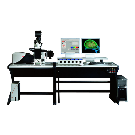
Specifications TCS SP5 specifications System overview figure1. System components (overview) 1 TCS SP5 Scanner 2 Control panel 3 TCS workstation 4 Supply unit 5 Panel box 6 Stand with scanner Page 11 User Manual TCS SP5 V: 02 | Document-ID-No.: 156500002... -
Page 18: Dimensions
Specifications Dimensions 5.2.1 System with inverted stand: figure2. Dimensions of the TCS SP5 with inverted stand Page 12 User Manual TCS SP5 V: 02 | Document-ID-No.: 156500002... -
Page 19: System With Upright Stand
Specifications 5.2.2 System with upright stand figure3. Dimensions of the TCS SP5 with upright stand Installation site requirements Do not expose the system to draft. Ensure that the system is not installed next to elevators, air conditioners or ventilation systems. For this reason, the installation site should be carefully planned. -
Page 20: Permissible Ambient Conditions
Installing the system in darke- ned rooms is also advisable. For installation, maintenance and trans- port, the TCS SP5 system requires doors with inside spans of 1.00 m. With regard to the load-bearing capacity of the floor, please note that the system will ap- ply a static load of 200 kg/m@. - Page 21 Specifications 200 V - 240 V AC power: 12-16 A For the specifications of external lasers such as UV and MP lasers, please refer to the ma- nufacturer’s documentation. Page 15 User Manual TCS SP5 V: 02 | Document-ID-No.: 156500002...
-
Page 22: Required Cooling Capacity
Specifications Required cooling capacity The TCS SP5 system has a maximum power consumption of 3.2 kW (VIS system). For the specifications of external lasers such as UV and MP lasers, please refer to the ma- nufacturer’s documentation. Important additional notes... -
Page 23: Required Safety Measures For Vis And Uv Systems
5.10 Important additional notes The optimal optical performance of the sy- stem can be achieved using standard objec- tives and standard immersions only at 22° Celsius + 1 °Celsius. Page 17 User Manual TCS SP5 V: 02 | Document-ID-No.: 156500002... - Page 24 Specifications Page 18 User Manual TCS SP5 V: 02 | Document-ID-No.: 156500002...
-
Page 25: Safety Notes
- EMC requi- rements” (Class A). This is a Class A device. Operating this device on a public low-voltage grid may result in radio interference. The operator Page 19 User Manual TCS SP5 V: 02 | Document-ID-No.: 156500002... - Page 26 No. 50, dated 26 July, 2001.”) For the scope of the CDRH/FDA (USA), the designation Laser Class 3B in the text must be replaced by IIIb and Class 4 by IV. Page 20 User Manual TCS SP5 V: 02 | Document-ID-No.: 156500002...
-
Page 27: Which Laser Class Does The Product Have
Laser class for MP systems According to IEC/EN 60825-1, this laser scanning microscope is a laser device of Class IV. Avoid exposing eyes or skin to direct and indirect radiation. Page 21 User Manual TCS SP5 V: 02 | Document-ID-No.: 156500002... -
Page 28: Warnings, Safety Cautions, And Notes
A high-voltage warning points out an ope- ration, a process, a condition or an instruc- tion that must be observed strictly to prevent possible injury or death of the persons using the system. Page 22 User Manual TCS SP5 V: 02 | Document-ID-No.: 156500002... -
Page 29: What Should The User Of The Laser Scanning Microscope Observe
In these cases, Leica Microsystems CMS GmbH does not assume any liability. According to IEC/EN 60825-1: ”Safety of laser products, Part 1: Equipment classification, requirements and user’s guide,”... - Page 30 Leica customer service representatives. If repairs or service measures are perfor- med that require opening parts of the housing, only trained Leica service tech- nicians may occupy the room in which the laser scanning microscope is located. Leica Micro-...
-
Page 31: Safety Notes For The User
Do not connect any external equipment. Connect only those electrical devices to the product that are listed in the Operating Instruc- tions. Otherwise, please contact your local Leica service agency or Leica Microsystems CMS GmbH. Page 25 User Manual TCS SP5... -
Page 32: Safety Notes For Operation
Maintain a safety distance of 20 cm between your eyes and the eyepiece opening. Page 26 User Manual TCS SP5 V: 02 | Document-ID-No.: 156500002... - Page 33 Page 27 User Manual TCS SP5 V: 02 | Document-ID-No.: 156500002...
- Page 34 Exchange the objective. - All unoccupied positions in the objec- tive turret must be closed using the sup- plied caps. Page 28 User Manual TCS SP5 V: 02 | Document-ID-No.: 156500002...
- Page 35 S70 micro- scope condensers could result in a threat from laser radiation. Therefore, only S1 and S23 Leica microscope condensers should be used. Page 29 User Manual TCS SP5...
-
Page 36: Specific Safety Notes
The supply unit must be set up so that the main circuit breaker is freely accessible at all times. figure5. Supply unit with main circuit breaker Page 30 User Manual TCS SP5 V: 02 | Document-ID-No.: 156500002... -
Page 37: Maximum Current Load Of The Power Outlet Strip At The Supply Unit
800 VA. The connectors are intended for: TCS control computer Monitor 1 Monitor 2 Microscope figure6. Power outlet strip, rear side of supply unit Page 31 User Manual TCS SP5 V: 02 | Document-ID-No.: 156500002... -
Page 38: Laser Safety Devices
For MP systems, see the chapter “Eye protection for MP systems”. Page 32 User Manual TCS SP5 V: 02 | Document-ID-No.: 156500002... -
Page 39: Detachable-Key Switch
Detachable-key switch of the external 405-nm Advance laser For lasers that are not connected as des- cribed above, please refer to the supplied manual of the laser manufacturer for the position of the detachable-key switches. Page 33 User Manual TCS SP5 V: 02 | Document-ID-No.: 156500002... -
Page 40: Emissions Warning Indicators
Immediately disconnect the system from power supply if any of the following oc- cur: The emission warning indicator is not lit after being switched on using the keys- witch. Page 34 User Manual TCS SP5 V: 02 | Document-ID-No.: 156500002... - Page 41 For lasers whose readiness is not indica- ted as described above, please refer to the supplied manual of the laser manufac- turer for the location of the emission war- ning indicator. Page 35 User Manual TCS SP5 V: 02 | Document-ID-No.: 156500002...
-
Page 42: Remote Interlock Connector On The Supply Unit
The laser beam path is interrupted if the contact is open. The overall length of the cable between the two connecting pins of the remote interlock connector should not exceed 10 m. Page 36 User Manual TCS SP5 V: 02 | Document-ID-No.: 156500002... -
Page 43: Remote Interlock Connector On The External 405Nm Advanced Laser
V, replacing the shorting plug by an exter- nal interrupt circuit (e.g. door interlock switch) may only be performed by a qualified electrician. 6.10.6 Remote interlock connectors on additional external lasers Page 37 User Manual TCS SP5 V: 02 | Document-ID-No.: 156500002... - Page 44 For lasers whose remote interlock con- nector is not indicated in Chapter 6.10.6, please refer to the supplied manual of the laser manufacturer for the location of the remote interlock connector. Page 38 User Manual TCS SP5 V: 02 | Document-ID-No.: 156500002...
-
Page 45: Interlock Connection On Scanner
The inverted microscope or, if an upright microscope is used, the mirror housing is connected to this connector. This ensures that the safety switch of the microscope is integrated in the interlock circuit. Page 39 User Manual TCS SP5 V: 02 | Document-ID-No.: 156500002... -
Page 46: Function And Position Of Safety Switches
DMI 4000 CS scanner is mo- from confocal ob- and eyepiece torized. servation to eye- piece observation. 6.10.9 Transmitted-light lamp housing for inverted stands Page 40 User Manual TCS SP5 V: 02 | Document-ID-No.: 156500002... - Page 47 Connecting the transmitted light lamp housing To prevent the emission of laser radia- tion, do not switch the lasers on without a lamp housing or cover on the microscope stand. Page 41 User Manual TCS SP5 V: 02 | Document-ID-No.: 156500002...
-
Page 48: Transmitted-Light Lamp Housing For Upright Stands
To prevent the emission of laser radia- tion, do not switch the lasers on without a lamp housing or mirror housing connec- ted to the microscope stand, or if a cover is not present. Page 42 User Manual TCS SP5 V: 02 | Document-ID-No.: 156500002... -
Page 49: Mirror Housing On Upright Stand
Mirror housing on upright stand To prevent the emission of laser radia- tion, do not switch the lasers on without a mirror housing or cover on the micro- scope stand. Page 43 User Manual TCS SP5 V: 02 | Document-ID-No.: 156500002... -
Page 50: Special Laser Safety Equipment
Do not swing in the filters during the scanning process. Page 44 User Manual TCS SP5 V: 02 | Document-ID-No.: 156500002... -
Page 51: Eye Protection For Mp Systems
Appropriate safety goggles for IR laser radia- tion are provided with the system when deli- vered. The supplied eye protection only provi- des safe protection against the infrared lasers supplied by Leica Microsystems CMS GmbH. Page 45 User Manual TCS SP5 V: 02 | Document-ID-No.: 156500002... -
Page 52: Shielding In Mp Systems (Uv Laser)
This shields the laser beam until it leaves the microscope objective and reaches the specimen. figure22. Safety beam guiding (1) and IR laser (2) Page 46 User Manual TCS SP5 V: 02 | Document-ID-No.: 156500002... -
Page 53: Overview Of Usable Vis/Uv Lasers
< 4 Continuous wave (cw) HeNe < 4 < 1 Continuous wave (cw) HeNe < 15 < 4 Continuous wave (cw) Table 1 Table of usable lasers (without MP) Page 47 User Manual TCS SP5 V: 02 | Document-ID-No.: 156500002... -
Page 54: Overview Of Usable Mp Lasers (Ir)
1.0-1.5 ps TiSa* 720-930 < 2.0 < 1.0 pulsed 1.0-1.5 ps TiSa* 720-980 < 2.5 < 1.2 pulsed 1.0-1.5 ps Table 2 Table of usable MP lasers Modified picosecond version Page 48 User Manual TCS SP5 V: 02 | Document-ID-No.: 156500002... -
Page 55: Safety Label On Tcs Sp5 System
Safety Notes 6.13 Safety label on TCS SP5 system The corresponding safety labels are selected dependent on the laser configuration (VIS, UV, MP) and attached in the following loca- tions. 6.13.1 Inverted stand DMI 4000/6000 CS Angled rear view of right side of stand figure23. -
Page 56: Upright Stand Dm 5000/6000 Cs
Safety Notes 88100–017 Zust. 00 52008–005 Zust.01 figure24. Safety label for DMI 4000/6000 CS inverted stand 6.13.2 Upright stand DM 5000/6000 CS Page 50 User Manual TCS SP5 V: 02 | Document–ID–No.: 156500002... - Page 57 Safety Notes Angled front view of right side of stand figure25. Safety label for DM 5000/6000 CS upright stand Page 51 User Manual TCS SP5 V: 02 | Document-ID-No.: 156500002...
- Page 58 Safety Notes Rear view of stand figure26. Safety label for DM 5000/6000 CS upright stand Page 52 User Manual TCS SP5 V: 02 | Document-ID-No.: 156500002...
-
Page 59: Scan Head
Safety Notes 6.13.3 Scan head Angled front view of left side of scan head figure27. Safety label for the scanner Page 53 User Manual TCS SP5 V: 02 | Document-ID-No.: 156500002... -
Page 60: Supply Unit
Safety Notes 6.13.4 Supply unit View of TCS SP5 supply unit. figure28. Safety label for the supply unit TCS SP 5 (front side) Page 54 User Manual TCS SP5 V: 02 | Document-ID-No.: 156500002... -
Page 61: External 405-Nm Laser Advance / 405-Nm Imaging Laser
Safety Notes 6.13.5 External 405-nm laser Advance / 405-nm imaging laser figure29. Safety label for the external 405-nm laser / safety label for the 405-nm imaging laser Page 55 User Manual TCS SP5 V: 02 | Document-ID-No.: 156500002... -
Page 62: External 488-Nm Laser
Safety Notes 6.13.6 External 488-nm laser figure30. Safety label for the external 488-nm laser Page 56 User Manual TCS SP5 V: 02 | Document-ID-No.: 156500002... - Page 63 6.13.7 MP beam coupling unit Angled front view of the right side of the beam coupling unit MP. figure31. Safety label for the beam coupling unit MP (top side) Page 57 User Manual TCS SP5 V: 02 | Document-ID-No.: 156500002...
-
Page 64: Cover (For Replacement Flange)
If the replacement flange for transmitted light is not equipped with a functional module such as a lamp housing, place a cover over the opening for laser safety reasons. Page 58 User Manual TCS SP5 V: 02 | Document-ID-No.: 156500002... -
Page 65: Requirements Related To The Installation/Storage Location
The instrument must be thoroughly dry before connecting it to the power supply or turning it on. Page 59 User Manual TCS SP5 V: 02 | Document-ID-No.: 156500002... -
Page 66: Changing The Installation Site
Pay not only attention to surfaces, but es- pecially to fans and cooling devices since dust can frequently accumulate at these locations. Page 60 User Manual TCS SP5 V: 02 | Document-ID-No.: 156500002... -
Page 67: Scanner Cooling
Safety Notes 6.16 Scanner cooling The scanner of the TCS SP5 is liquid-cooled. Observe the attached safety data sheet pro- vided by the manufacturer, Innovatek, regar- ding the coolant used. In case of a coolant leak, switch the power off immediately! Inform Leica or a Leica-approved service facility immediately. - Page 68 Safety Notes Page 62 User Manual TCS SP5 V: 02 | Document-ID-No.: 156500002...
-
Page 69: Care And Cleaning
Care and Cleaning Care and cleaning Please refer to the corresponding manuals for information on how to maintain the Leica research microscope. The instructions and additional information relating to the components of the confocal system are summarized below. Protect the microscope from dust and grease. -
Page 70: Cleaning The Microscope Surface
If an objective lens is accidentally contamina- ted by unsuitable immersion oil or by the specimen, please contact your local Leica branch office. for advice on the use of certain solvents for cleaning purposes. Take this seriously, because some solvents may dissolve the glue which holds the lens in place. - Page 71 Care and Cleaning Never use acetone, xylene or nitro thinners as they attack the varnish. All LEICA components and systems are ca- refully manufactured using the latest produc- tion methods. If you encounter problems in spite of our efforts, do not try to fix the devi- ces or the accessories yourself, but contact your Leica representative.
- Page 72 Care and Cleaning Page 66 User Manual TCS SP5 V: 02 | Document-ID-No.: 156500002...
-
Page 73: Startup Of The System
Startup of the System Startup of the system Proceed as follows to start your TCS SP5 system: Switch on the TCS workstation. figure33. Switching on the workstation Check whether the microscope stand is switched on. If the readiness indicator (Figure 31/1) on the MIC box is lit, the stand is operating. - Page 74 Typing your password identifies you as a valid user for this computer. The default user name for the Leica TCS SP5 system is ”TCS_User”. A standard password was not set. It is re- commended setting up a separate user ID for each user (system administrator).
- Page 75 Startup of the System Then click the OK button. Your new password will be in effect the next time you log on. Page 69 User Manual TCS SP5 V: 02 | Document-ID-No.: 156500002...
-
Page 76: Setting Up Users
Factory-installed hard disks are provided with two partitions (C:\ and D:\). The user di- rectory should be set up on partition D:\. Page 70 User Manual TCS SP5 V: 02 | Document-ID-No.: 156500002... - Page 77 Startup of the System figure35. The ”booted” system Wait until the boot process of the TCS workstation is completed. If not yet done, create a user and log on. Page 71 User Manual TCS SP5 V: 02 | Document-ID-No.: 156500002...
- Page 78 Startup of the System Turn on the TCS SP5 scanner. figure36. Turning on the scanner figure37. Turning on the scanner The Windows status bar must show the ”SP5 Scanner Gigabit Interface” as connected! Page 72 User Manual TCS SP5 V: 02 | Document-ID-No.: 156500002...
- Page 79 Laser radiation may be present in the specimen area as of this time. Follow the safety instructions given in Chapter 6. Please follow the instructions in Chapter 14 to switch off the TCS SP5 system. Page 73 User Manual TCS SP5 V: 02 | Document-ID-No.: 156500002...
- Page 80 Startup of the System Page 74 User Manual TCS SP5 V: 02 | Document-ID-No.: 156500002...
-
Page 81: Starting The Las Af
Starting the LAS AF Starting the LAS AF Start the LAS AF by double-clicking the program icon. figure40. Starting the LAS AF Page 75 User Manual TCS SP5 V: 02 | Document-ID-No.: 156500002... - Page 82 Resonant or non-resonant If you purchased this option, you can start the system in resonant or non-reso- nant mode at this point. Select whether the TCS SP5 system should be operated in resonant or non- resonant mode. Page 76 User Manual TCS SP5...
- Page 83 Starting the LAS AF figure42. LAS AF start window Start the LAS AF by clicking on ”OK”. Page 77 User Manual TCS SP5 V: 02 | Document-ID-No.: 156500002...
- Page 84 Starting the LAS AF figure43. LAS AF base view You are now in the base view of the LAS AF. Start the LAS AF help with the F1 key. Page 78 User Manual TCS SP5 V: 02 | Document-ID-No.: 156500002...
-
Page 85: Introduction To Las Af - Help
The online help can be called in two ways: In the respective context (context-sensi- tive) Via the Help menu Page 79 User Manual TCS SP5 V: 02 | Document-ID-No.: 156500002... -
Page 86: Structure Of The Online Help
They are divided into two categories: for be- ginners and for advanced users. Additional information This book contains detailed descriptions about certain topics of biology, image editing, filter... Page 80 User Manual TCS SP5 V: 02 | Document-ID-No.: 156500002... -
Page 87: Imprint
The contents of this online help may not be reproduced or transmitted by electronic or mechanical means, in whole or in part, wi- thout the express permission of Leica Micro- systems CMS GmbH. This also includes photocopying, recording or storing on a re- trievable system as well as the translation into another language. -
Page 88: In The Respective Context (Context-Sensitive)
Display button. Search Enter the term or definition you want to look up and click on the LIST TOPICS button. A hierarchically structured list of topics is re- turned. Page 82 User Manual TCS SP5 V: 02 | Document-ID-No.: 156500002... -
Page 89: Full-Text Search With Logically Connected Search Terms
Pinhole not sec- This phrase finds help topics containing the word ”pinhole” and not containing the tions word ”sections”. Page 83 User Manual TCS SP5 V: 02 | Document-ID-No.: 156500002... -
Page 90: Key Combinations
In order to accelerate recurring software functions, special key combinations have been defined: CTRL + N Opens a new experiment CTRL + O Starts the Open dialog window to open an existing file. Page 84 User Manual TCS SP5 V: 02 | Document-ID-No.: 156500002... -
Page 91: Structure Of The User Interface
Configuration Acquire Process Quantify Application Tab area: Different tabs belong to every operating step (arrow symbol) in which the settings for the experiment can be made. Page 85 User Manual TCS SP5 V: 02 | Document-ID-No.: 156500002... - Page 92 In the standard setting, the Vie- wer window consists of the image win- dow in the center and the buttons for image editing (5a) and channel display (5b). Page 86 User Manual TCS SP5 V: 02 | Document-ID-No.: 156500002...
-
Page 93: What Is The Köhler Illumination
Köhler illumination represents a compromise between maximum contrast and maximum resolution. The most efficient microscope ob- jectives frequently reach their optimum optic performance only with exactly adjusted Köh- ler illumination. Page 87 User Manual TCS SP5 V: 02 | Document-ID-No.: 156500002... -
Page 94: Setting The Köhler Illumination
In this case, open the field diaphragm until you can just see the light spot at the border of the image field. figure45. Field diaphragm Page 88 User Manual TCS SP5 V: 02 | Document-ID-No.: 156500002... - Page 95 (open to ap- proximately 70% of the maximum diameter). If you change the objective It may become necessary to readjust the Köhler illumination after you have changed the objective. Page 89 User Manual TCS SP5 V: 02 | Document-ID-No.: 156500002...
- Page 96 Koehler Illumination Page 90 User Manual TCS SP5 V: 02 | Document-ID-No.: 156500002...
-
Page 97: Introduction To Confocal Work
(i.e. the top side of embedded specimens) is facing down. Background information has also been provi- ded to explain the reasons behind various settings. These are not descriptions of the Page 91 User Manual TCS SP5 V: 02 | Document-ID-No.: 156500002... -
Page 98: The Objective
80% and water may be used as im- mersion media (Table 3). Apply the immer- sion medium generously, but be sure that it does not flow into the stand of inverted mi- croscopes. Page 92 User Manual TCS SP5 V: 02 | Document-ID-No.: 156500002... -
Page 99: Conventional Microscopy
Reflective specimens can also provide interesting results, however. (Fig. 44) Filter cubes suitable to the fluore- scence must be positioned in the beam when Page 93 User Manual TCS SP5 V: 02 | Document-ID-No.: 156500002... - Page 100 Introduction to Confocal Work viewing the specimen via the eyepieces. For more information on selecting fluorescence filter cubes, please refer to the Leica fluore- scence brochure or contact your Leica part- ner. For a selection of filter cubes, see Table 4 below.
- Page 101 Introduction to Confocal Work Filter cube Excitation filter Dichroic mirror Emission filter 430;500 B/G/R 435;565 BFP/GFP FI/RH N2,1 Table 4 Selection of filter cubes for Leica research microscopes and associated filter specifications. Page 95 User Manual TCS SP5 V: 02 | Document-ID-No.: 156500002...
-
Page 102: Why Scan
Illustration of the raster scan. Two mirrors move the illumination spot in x and y direc- tions across the specimen in rows so that the entire image can be reconstructed in parallel. Page 96 User Manual TCS SP5 V: 02 | Document-ID-No.: 156500002... - Page 103 The signals from the specimen are written to an image memory and can be displayed on the monitor. Page 97 User Manual TCS SP5 V: 02 | Document-ID-No.: 156500002...
-
Page 104: How Is An Optical Section Created
As a rule, the optical section becomes thin- ner when the size of the pinhole is reduced. This effect is reduced near the wavelength of the light used, and at a pinhole diameter of Page 98 User Manual TCS SP5 V: 02 | Document-ID-No.: 156500002... - Page 105 A value of 1 Airy is a very good com- promise and is selected automatically by the Leica TCS SP5. A dialog is available to set smaller or larger diameters if required. Playing with this parameter to study its ef- fects can be very worthwhile when you have the time.
-
Page 106: Acquiring Optical Sections
Introduction to Confocal Work 13.2 Acquiring optical sections figure51. Use the ”Acquire” arrow button to acquire data in all Leica LAS AF applications. The Leica TCS SP5 contains many functions in its user interface that reflect its wide range of potential applications. The functions not... -
Page 107: Data Acquisition
The ”Live” button starts data acquisition in all Leica LAS AF applications. This is a preview mode suitable for setting up the instrument. Stopping data acquisition will also immediately stop the scan process, even if the image has not been fully rende- red. - Page 108 The specimen can be used for a wide range of fundamental problems and has the advantage that it practically does not bleach. Page 102 User Manual TCS SP5 V: 02 | Document-ID-No.: 156500002...
-
Page 109: Illumination
If all of the other settings are in order, darker and lighter images will be visible on the mo- Page 103 User Manual TCS SP5 V: 02 | Document-ID-No.: 156500002... -
Page 110: Beam Splitting
”Stokes shift”, and its degree depends on the fluorochrome. As a rule, the excitation and de-excitation spectra overlap, and the Stokes shift is the difference between the ex- citation maximum to the emission maximum. Page 104 User Manual TCS SP5 V: 02 | Document-ID-No.: 156500002... - Page 111 Using the ex- citation lines and displayed emission charac- teristics for orientation and adapting the ® emission band using the Leica SP detection system is thus very convenient. This is also true while images are being captured.The...
-
Page 112: The Pinhole And Its Effects
However, the effect would be lost if the pinhole were too wide, as the image would contain excessive blurred sha- res of the specimen from above and below the focal plane. Page 106 User Manual TCS SP5 V: 02 | Document-ID-No.: 156500002... - Page 113 A pinhole diameter of 1 Airy is therefore the default setting. Switching objectives also ad- justs the diameter of the pinhole accordingly. Page 107 User Manual TCS SP5 V: 02 | Document-ID-No.: 156500002...
-
Page 114: Image Detail And Raster Settings
40x can be achieved sim- ply by moving a slider. As always in microscopy, the total Page 108 User Manual TCS SP5 V: 02 | Document-ID-No.: 156500002... - Page 115 (Nyquist theo- rem). That would be an image with 4800x4800 pixels. Some purists require 3x oversampling, i.e. 7200x7200 pixels, or 52 Page 109 User Manual TCS SP5 V: 02 | Document-ID-No.: 156500002...
- Page 116 Introduction to Confocal Work megapixels. Image formats for x and y can be adjusted independently and in very fine steps, with the Leica TCS SP5 supporting capture formats of up to 64 megapixels (8000x8000 pixels) (Table 5). Magnification Numerical Aperture 1,25 μm...
- Page 117 200nm and 300nm. Larger spacings would lead to a loss of resolution when using an objective with an aperture of 0.4 (Fig. 58). Page 111 User Manual TCS SP5 V: 02 | Document-ID-No.: 156500002...
- Page 118 An additional parameter is required here: the rotation of the scan field. As field rotation is performed optically in the Leica TCS SP5, rotation by +/- 100° does not have any effect on the speed and possible grid formats (Fig. 59).
-
Page 119: Signal And Noise
– i.e. green. To be safe, the offset can be set one or two grayscale values higher to ensure that the lower signal values are not truncated. The Page 113 User Manual TCS SP5 V: 02 | Document-ID-No.: 156500002... - Page 120 The signal-to-noise ratio may be influenced by a number of other factors in addition to illumination intensity: the speed at which data is captured. The actual speed of the Page 114 User Manual TCS SP5 V: 02 | Document-ID-No.: 156500002...
- Page 121 A general rule of thumb for all application situa- tions thus does not exist. Choosing the best method is a matter of experimentation and experience. Page 115 User Manual TCS SP5 V: 02 | Document-ID-No.: 156500002...
-
Page 122: Profile Cuts
Camera-based systems (also ”confocal” sy- stems) can only compute such profiles out of complete stacks (Fig. 61). Page 116 User Manual TCS SP5 V: 02 | Document-ID-No.: 156500002... -
Page 123: Multiparameter Fluorescence
The depiction in the colors green and red is arbitrary. Fluorescence and reflection images can also be rendered at the same time. Using a single excitation, this merely requires observing a second ”emission band” below the laser line. Page 117 User Manual TCS SP5 V: 02 | Document-ID-No.: 156500002... -
Page 124: Beam Splitting
2nm. Everything else is available to capture the emission. A suitable beam splitter must be selected when using instruments with traditional beam splitters. In this regard, it is important to Page 118 User Manual TCS SP5 V: 02 | Document-ID-No.: 156500002... -
Page 125: Emission Bands
This should naturally be avoided, as it leads to the display of incorrect Page 119 User Manual TCS SP5 V: 02 | Document-ID-No.: 156500002... - Page 126 The emission characteristics of the stains used can be displayed in the user interface, and a lot can be gained if the emission bands are restricted to ranges that do not Page 120 User Manual TCS SP5 V: 02 | Document-ID-No.: 156500002...
-
Page 127: Sequential Capture
However, we recommend optimizing separation with the means provided by the instrument (see 3.4 and 3.5) to the greatest extent possible and Page 121 User Manual TCS SP5 V: 02 | Document-ID-No.: 156500002... - Page 128 This is also covered by a variety of methods available in the Leica software. It is advisable to experiment a bit to determine the best method for the task at hand. As all...
- Page 129 This method is especially suited for situations in which the stains do not signifi- cantly change their emission in situ and in which the related data is well-known. Page 123 User Manual TCS SP5 V: 02 | Document-ID-No.: 156500002...
-
Page 130: Series
0.5μm and 2.5μm for apertures from 0.7 to 1.4. These are typical values in practice. In the literature – espe- cially in advertising materials – the thickness Page 124 User Manual TCS SP5 V: 02 | Document-ID-No.: 156500002... -
Page 131: And Spacing
(i.e. a 20μm thick specimen at high resolution) already require 25MB, which only a couple of years ago amounted to a very cumbersome volume of data. If 5 chan- Page 125 User Manual TCS SP5 V: 02 | Document-ID-No.: 156500002... - Page 132 64 GB, a volume that most modern computers cannot handle with ease. A criti- cal assessment of the data capture parame- ters to be used is definitely called for here. Page 126 User Manual TCS SP5 V: 02 | Document-ID-No.: 156500002...
-
Page 133: Depictions
– rather like a stamp collection (Fig. 66). Changes from section to section can thus be analyzed and the images printed in periodicals. Page 127 User Manual TCS SP5 V: 02 | Document-ID-No.: 156500002... -
Page 134: Movie
This representation is known as ”height-color coded extended depth of focus” (Fig.65). The SFP (simulated fluorescence projection) method uses a more complex approach to Page 128 User Manual TCS SP5 V: 02 | Document-ID-No.: 156500002... -
Page 135: Rotated Projections
(red-green ana- glyph). This is simpler for most users, but cannot be applied to multiparameter data. Page 129 User Manual TCS SP5 V: 02 | Document-ID-No.: 156500002... - Page 136 3D movies of this type are today the most common and convincing means of displaying three-dimen- sional data. Page 130 User Manual TCS SP5 V: 02 | Document-ID-No.: 156500002...
-
Page 137: Time Series
It is the- refore necessary to verify the parameters that truly require measurement. A central dif- ference between various measurements is the dimensionality that attempts to compen- sate for mechanical limits. Page 131 User Manual TCS SP5 V: 02 | Document-ID-No.: 156500002... -
Page 138: Points
This amounts to measuring the changes in light intensity at a fixed, preselected point in the Leica TCS SP5 with a temporal resolution of 40MHz (corresponding to 25ns). Naturally, that parti- cular spot in the specimen can be expected to bleach within a very short time. -
Page 139: Spaces (Time-Space)
Such experiments can be used to make de- ductions about membrane permeability, diffu- sion speeds and the binding behavior of mo- lecules. The capture of a time series is always integral to such measurements. Page 133 User Manual TCS SP5 V: 02 | Document-ID-No.: 156500002... -
Page 140: Spectral Series
The TCS SP5 supports the adjustment of emis- sion bands in 1nm steps,which corresponds to a formal resolution of one nanometer. The... -
Page 141: Combinatorial Analysis
The synthesis of a broad range of measurements is often difficult and always requires a solid intellectual overview to avoid the creation of data graveyards and incorrect conclusions. Page 135 User Manual TCS SP5 V: 02 | Document-ID-No.: 156500002... - Page 142 Introduction to Confocal Work Page 136 User Manual TCS SP5 V: 02 | Document-ID-No.: 156500002...
-
Page 143: Switching Off The System
Next, turn off the switches on the con- trol panel for the TCS workstation and the TCS SP5 (Fig. 67/4/5) scanner. The external fan of the argon laser will switch off automatically after several mi- nutes. Also set the switch for the lasers (Fig. - Page 144 Switch off the microscope and any acti- vated fluorescence lamps If your system features external lasers (IR, UV or others), switch them off in ac- cordance with their respective manuals. Page 138 User Manual TCS SP5 V: 02 | Document-ID-No.: 156500002...
-
Page 145: Contact
Contact Contact If you have any further questions related to your TCS SP5, please contact the Leica branch office in your country. Please refer to the country list below for con- tact information. If your country is not listed below, please use the area selector at http://www.confocal-mi-... - Page 146 Contact Page 140 User Manual TCS SP5 V: 02 | Document-ID-No.: 156500002...
-
Page 147: Declaration Of Conformity
Declaration of Conformity Declaration of conformity Page 141 User Manual TCS SP5 V: 02 | Document-ID-No.: 156500002... - Page 148 Declaration of Conformity Page 142 User Manual TCS SP5 V: 02 | Document-ID-No.: 156500002...
-
Page 149: Glossary
(usually 450 nm, 550 nm and 650 nm) and the sine condition is met for at least two co- lors. The image curvature aberration is not corrected. Page 143 User Manual TCS SP5 V: 02 | Document-ID-No.: 156500002... - Page 150 Instrument parameter settings labeled with the letter «L» are predefined by Leica and cannot be changed. User-defined, modi- fiable instrument parameter settings are sto- red below «U»...
- Page 151 488 nm and 568 nm is reflected and above these values it is transmitted. The transmission values are generally at 80% and the reflection values are between 90% and 95%. Experiment Page 145 User Manual TCS SP5 V: 02 | Document-ID-No.: 156500002...
- Page 152 Glossary A file with Leica-specific data format (*.lei) that consists of one ore more individual images or image series. Images recorded with different scan parameters or result images from image processing can be com- bined here. Fluorescent dye A dye used for analysis that reacts with the emission of light of other wavelengths upon excitation with light energy (Stokes shift).
- Page 153 (50% threshold). Lambda series Stack of individual images of a single optical plane that were each detected at a specific wavelength. Reflection long pass filter Page 147 User Manual TCS SP5 V: 02 | Document-ID-No.: 156500002...
- Page 154 (NA = n * sina) is gene- rally used as the unit of measure for the lumi- nous intensity and the resolution capacity. Page 148 User Manual TCS SP5 V: 02 | Document-ID-No.: 156500002...
- Page 155 Phase visualization The principle of phase visualization as used by Leica is an optimized alternative method to ratiometric displaying. The main area of application is the measurement of ion con- centrations in physiology. In contrast with ra- tiometric procedures, phase visualization ob- tains more information on the specimen.
- Page 156 80% and the re- flection values are between 90% and 95%. Dry objective A microscopic objective used without immer- sion media. Between the objective lens and the specimen is air. Page 150 User Manual TCS SP5 V: 02 | Document-ID-No.: 156500002...
- Page 157 3D image points are referred to as vo- xels. z-stack Z-stacks are comprised of two-dimensional images that were recorded on different focal planes and displayed as three-dimensional. Page 151 User Manual TCS SP5 V: 02 | Document-ID-No.: 156500002...
- Page 158 Glossary Page 152 User Manual TCS SP5 V: 02 | Document-ID-No.: 156500002...
-
Page 159: Safety Data Sheets
Safety Data Sheets Safety data sheets The following are safety data sheets from third-party manufacturers. Page 153 User Manual TCS SP5 V: 02 | Document-ID-No.: 156500002... - Page 160 Safety Data Sheets Page 154 User Manual TCS SP5 V: 02 | Document-ID-No.: 156500002...
- Page 161 Safety Data Sheets Page 155 User Manual TCS SP5 V: 02 | Document-ID-No.: 156500002...
- Page 162 Safety Data Sheets Page 156 User Manual TCS SP5 V: 02 | Document-ID-No.: 156500002...
- Page 163 Safety Data Sheets Page 157 User Manual TCS SP5 V: 02 | Document-ID-No.: 156500002...
- Page 166 Leica Microsystems CMS GmbH Tel.: +49 (0)621 7028 - 0 Am Friedensplatz 3 Fax: +49 (0)621 7028 - 1028 D-68165 Mannheim (Germany) http://www.leica-microsystems.com Copyright © Leica Microsystems CMS GmbH • All rights reserved Order No.: 156500002...
Need help?
Do you have a question about the TCS SP5 and is the answer not in the manual?
Questions and answers