Leica TCS SP8 Quick Start Manual
Hide thumbs
Also See for TCS SP8:
- User manual (118 pages) ,
- Safety manual (18 pages) ,
- User manual (13 pages)
Table of Contents
Advertisement
Advertisement
Table of Contents

Subscribe to Our Youtube Channel
Related Manuals for Leica TCS SP8


Summary of Contents for Leica TCS SP8
- Page 1 Leica TCS SP8 Quick Start Guide...
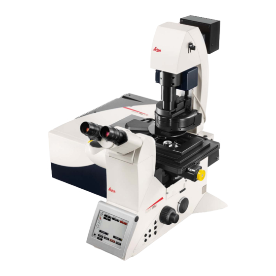
- Page 2 Leica TCS SP8 System Overview...
- Page 4 10. Click OK to start the initialization of the LAS AF (Leica Application Suite for Advanced Fluorescence) 11. A message will appear asking whether you want to initialize the stage. Initializing the stage is required to activate the Tiling and Mark &...
- Page 5 Shut-Down Procedure Turn off the lasers in the software 2. Lower the objective to the lowest position, remove specimen and clean all of the objectives 3. Save all unsaved data and exit LAS X. NOTE: Do not turn off scanner and/or CTR control box for the microscope before the software is closed 4.
- Page 6 The LAS X software will open in the Acquire tab. There are 3 portions to this window: Scan Parameters Light Path Image...
- Page 7 Turning on the Lasers: Click on the “+” in the Laser Lines Box in the Beam Path Settings Window to directly open the main Laser Control Window Activate the lasers you require NOTE: Only turn on the laser(s) with the appropriate laser line(s) that will excite the fluorophores you are using Alternatively, click on the Configuration tab and the Laser icon to open the main Laser Control Window...
- Page 8 Additional Tools in the Configuration Tab… 1. Customize the USB Control Panel - assign various parameter and sensitivities to the various knobs of the control panel Save and Load the customized settings Alternatively , click on the Control Panel Icon in the Beam Path Settings Window as a short cut to the USB Control Panel Window 2.
- Page 9 Emission spectrum from a lambda scan can be added to the dye database. Many manufacturer’s will also provide the data for fluorophores that can added to the database (see LAS AF Help) Another great resource is the Leica FluoScout interactive tool http://www.leica-microsystems.com/fluoscout/...
- Page 10 Beam Path Setting Option #1: Manual setting of the beam path configuration 2. Adjust the laser intensity 1. Click to activate of the appropriate laser the lasers line(s) by moving the slider up or by directly entering the level (start low as a suggestion).
- Page 11 Beam Path Setting Option #2: Dye Assistant to set beam path configuration The Dye Assistant offers suggestion on system configuration based on the spectral characteristics of the fluorescent dyes being used. The user can select the appropriate option for his or her application 1.
- Page 12 The following settings are mode for image acquisition when clicking Apply: • Selection of the laser lines • Selection of the detectors • Setting for the detection range • Assignment of the fluorescent dyes to the respective detectors • Assignment of the appropriate colour look-up table (LUT) for the respective fluorescent dyes\ All other settings for image acquisition are made as usual...
- Page 13 Beam Path Setting Option #3: Load/Save specific settings The settings can be saved for subsequent experiments with the same or similar specimens. Click on the diskette icon to save a setting SUGGESTION: Include your name or initials when saving the settings to identify who created the configuration.
- Page 14 Beam Path Setting - Sequential Acquisition 1. Click SEQ to open the Sequential Scan control window 2. Set the light path configuration for the first sequence (ie laser, beam splitter, detector, emission window, etc,) 3. Select switching mode and click to add a sequential scan Turning on or off lasers and detectors 4.
- Page 16 Acquisition Parameters Format or # of pixels in the image (start with 512 x 512) Scan Speed (start with 400-600 Hz) Option for bidirectional for ~2x faster acquisition (may need to adjust phase) Adjust zoom factor various ways by: • Adjusting slider •...
- Page 17 Acquisition Modes: Select the appropriate Acquisition Mode • xyz – single image or z-stack • xzy – xz image • xyt – time series • xyzt -- z-stack and time series • xy – lambda scan Z Stack (xyz) 1. Select xyz as the Acquisition Mode 2.
- Page 18 Z Stack (xyz) continued… Use arrows to move to the set Begin or End position Use Set Focus to define current position as the focal plane Delete Begin and End Positions Move to set focal position Move to centre position of stack Change direction of acquisition of the stack...
- Page 19 Additional Acquisition Mode – Tile Scan 1. Activate Tile Scan acquisition mode NOTE: the stage must be initialized during the start-up Option 1 2. Move the specimen to the opposite 1. Move the specimen to the position that will a corner of the tile scan and mark the corner of the tile scan using the SmartMove new position.
- Page 20 Additional Acquisition Mode – Mark & Find 1. Activate Mark & Find in acquisition mode NOTE: the stage must be initialized during the start-up Click to delete current saved Move the stage using the SmartMove and position or all saved mark the position of interest.
- Page 21 Region-of-Interest (ROI) Scanning 1. Turn on ROI Scanning and draw ROI(s) in image (use tools at top of image window) 3. To adjust the laser intensity for the 2. Open the ROI Configuration “background”, turn on Set Background and window by clicking on the “+”. then adjust the laser intensity sliders.
- Page 22 Transmitted Light Image – Brightfield or DIC Go to the following link for a tutorial on the basic concepts of DIC http://www.leica-microsystems.com/science-lab/differential-interference-contrast/ 1. Ensure Koehler Illumination of the microscope is set correctly http://www.leica-microsystems.com/science-lab/koehler-illumination/ 2. Activate a laser line 3. Turn on Transmitted PMT and select Scan-BF or Scan-DIC 4.
- Page 23 Experiment/Project Tree – Saving Images Right Click on an image for more options...
- Page 25 Additional Information - Spectral (SP) Detection System This particular system has 3 separate internal detectors for confocal imaging The Leica TCS SP8 does not use emission filters to define the wavelengths of emission collected, but rather utilizes a prism-based approach.
- Page 26 Optimizing Pixel Format (Resolution) Since the PSF for confocal is ~30% smaller due to the pinhole and the following formula applies Requires a sampling frequency of at least 2x-3x the highest spatial frequency to accurately preserve the spatial resolution in the resulting digital image Too few pixels –...
Need help?
Do you have a question about the TCS SP8 and is the answer not in the manual?
Questions and answers