Table of Contents
Advertisement
2016.11
Part # 520.0148 / 520.0208
Processes
MIG/MAG(GTAW) Arc Welding
Flux-Cored (FCAW) Arc Welding
115 & 220VAC 50/60Hz
INVERTER MIG WELDING MACHINE
M148 / M208
OPERATOR'S MANUAL
IMPORTANT: Read this Owner's Manual Completely before attempting to use this
equipment. Save this manual and keep it handy for quick reference. Pay particular
attention to the safety instructions we have provided for your protection. Contact your
distributor if you do not fully understand this manual.
.
Advertisement
Table of Contents

Related Manuals for Matco Tools M148


Summary of Contents for Matco Tools M148
- Page 1 MIG/MAG(GTAW) Arc Welding Flux-Cored (FCAW) Arc Welding 115 & 220VAC 50/60Hz INVERTER MIG WELDING MACHINE M148 / M208 OPERATOR’S MANUAL IMPORTANT: Read this Owner’s Manual Completely before attempting to use this 2016.11 equipment. Save this manual and keep it handy for quick reference. Pay particular attention to the safety instructions we have provided for your protection.
-
Page 2: Table Of Contents
CONTENT §1 SAFETY ..........................1 §1.1 S ......................1 IGNAL XPLANATION §1.2 A ..................... 1 ELDING AMAGE §1.3 T ............5 HE KNOWLEDGE OF LECTRIC AND AGNETIC IELDS §2 OVERIVEW ........................... 7 § 2.1 B ....................... 7 RIEF NTRODUCTION §2.2 W ...................... -
Page 3: Safety
§1 Safety §1.1 Signal Explanation The above signals mean warning! Notice! Running parts and getting an electric shock or thermal parts will take damage for your body or others. The corresponding notices are as follows. It is quite a safe operation after taking several necessary protection measures. §1.2 Arc Welding Damage ... - Page 4 SAFETY touch these “hot” parts with your bare skin or wet clothing. Wear dry, hole-free gloves to insulate hands. In semiautomatic or automatic wire welding, the electrode, electrode reel, welding head, nozzle or semiautomatic welding gun are also electrically “hot”. ...
- Page 5 SAFETY to be used, including the material safety data sheet and follow your employer’s safety practices. ARC RAYS CAN BURN. Use a shield with the proper filter and cover plates to protect your eyes from sparks and the rays of the arc when welding or observing open arc welding. ...
- Page 6 SAFETY prevent hazardous situation. When not welding, make certain no part of the electrode circuit is touching the work or ground. Accidental contact can cause overheating and create a fire hazard. Do not heat, cut or weld tanks, drums or containers until the proper steps have been taken to insure that such procedures will not cause flammable or toxic vapors from substances inside.
-
Page 7: Fields
SAFETY §1.3 Knowledge of Electric and Magnetic Fields Electric current flowing through any conductor causes localized Electric and Magnetic Fields (EMF). The discussion on the effect of EMF is ongoing all the world. Up to now, no material evidences show that EMF may have effects on health. However, the research on damage of EMF is still ongoing. -
Page 8: Brief Introduction
OVERVIEW §2 Overview §2.1 Brief Introduction The M-Series of MIG, MAG INVERTER arc welding machine adopts the latest pulse width modulation (PWM) technology and insulated gate bipolar transistor (IGBT) power module, which can change work frequency to medium frequency so as to replace the traditional hulking work frequency transformer with the compact medium frequency transformer. -
Page 9: Working Principle
OVERVIEW §2.2 Working Principle The working principle of M-SERIES arc welding machine is shown as the following figure. single-phase 110 or 220V work frequency AC is rectified into DC(154V), then is converted to medium frequency AC (about 37KHz) by inverter device (IGBT), after reducing voltage by medium transformer (the main transformer) and rectifying by medium frequency rectifier (fast recovery diodes), and is outputted by inductance filtering. - Page 10 OVERVIEW §2.4Principles of welding...
-
Page 11: Installation And Adjustment
INSTALLATION AND ADJUSTMENT §3 Installation and Adjustment §3.1 Parameters Model M148 (110VAC) M208 (220VAC) Parameters Input Voltage 1~110/115±10% 1~208-240±5% (V) Input Current 20 (max.) 20 (max.) (A) Input Power (KW) Welding 35~140 50~200 Current(A) No-load Voltage(V) Duty cycle 40%130A 100%95A 25%200A 100%120A (40℃)... -
Page 12: Equipment Connection
INSTALLATION AND ADJUSTMENT §3.3 Equipment Connection Operation Steps: 1. Connect the NEMA plug power cord of welding machine to matching electric outlet. 2. Connect input shield gas hose from regulator to input fitting on back of machine. 3. Connect the negative (-) cable clamp to the work piece (base metal). 4. -
Page 13: Operation
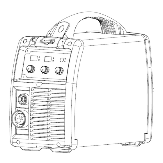
OPERATION §4 Operation §4.1 Layout for the front and rear panel... -
Page 14: Welding Operation
OPERATION 1. Voltage Display: Set desired welding voltage before welding. Displays actual welding voltage when machine is working. 2. Alarm Led: When the machine senses LINE over voltage or low voltage, output over current or over heat condition, the alarm pilot lamp will be on. 3. -
Page 15: Welding Parameters
OPERATION §4.3 Welding parameters Wire speed (A) (V) Welding current Welding volt Wave control φ0.6 φ0.8 φ1.0 2--3 13~15V 3--5 2--3 14~16V 6--8 3--5 2--3 15~17V 100A 8--10 3--6 16~19V 120A 17~20V 4--7 3--5 140A 19~21V 5-10 5--8 3--5 160A 20~22V 5-10 6--9... -
Page 16: Maintenance
THANK YOU FOR USING OUR PRODUCTS s§5 Maintenance & Troubleshooting §5.1 Maintenance In order to guarantee that arc welding machine works high-efficiently and in safety, it must be maintained regularly. Let customers understand the maintenance methods and means of arc welding machine more , enable customers to carry on simple examination and safeguarding by oneself, try one's best to reduce the fault rate and repair times of arc welding machine, so as to lengthen service life of arc welding machine .Maintenance items in detail are in the following... -
Page 17: Troubleshooting
THANK YOU FOR USING OUR PRODUCTS §5.2 Troubleshooting All welding machines have undergone 100% inspection before leaving the factory. Disconnect power cord from LINE before any trouble shooting and only professional maintenance personal should perform any action on the machine! Item Trouble Reasons... - Page 18 THANK YOU FOR USING OUR PRODUCTS §5.3 Wire Feeding Maintenance The welding wire must travel smoothly and freely from the spool all the way to the weld pool for controlled welding. Poor welding performance is many times a result of mechanical feeding problems with the wire through the torch.
- Page 19 THANK YOU FOR USING OUR PRODUCTS §5.4 Changing the Feed Roll The wire feed roller is factory set for welding filler wires 0.8 – 0.9mm (.030” - .035”). The roller has a 0.6mm (.023”) diameter groove on the other side; therefore, the feed roller side must be changed if you use 0.6mm thick filler wire.
- Page 20 THANK YOU FOR USING OUR PRODUCTS §5.5 Replacement Exploded Parts Drawing Part Number Description Qty. Handle, Machine CP 520.3010 1.00 Cabinet, Cover 148/208 520.3050 1.00 Latch, Wire Feed Door CP 520.3011 1.00 Cabinet, Wire Feed Door 148/208 520.3051 1.00 Cabinet, Rear Panel 148/208 520.3052 1.00 Power Switch...
- Page 21 Front Control Plate 520.3056 1.00 Shunt 148/208 520.3030 1.00 Control PCB 148/208 1.00 520.3031 Cabinet, Front Panel 148/208 1.00 520.3057 Power Inverter M148 1.00 520.3005 Power Inverter M208 1.00 520.3006 520.3032 Burn Back Potentiometers PCB 1.00 Power Board 148/208 1.00 520.3033 Output Adaptor Brass Panel Mount 148/208 520.3034...
- Page 22 THANK YOU FOR USING OUR PRODUCTS §5.6 MIG Gun Exploded Parts...
- Page 23 THANK YOU FOR USING OUR PRODUCTS §5.5 Electrical Schematic Drawing...
Need help?
Do you have a question about the M148 and is the answer not in the manual?
Questions and answers