Table of Contents
Advertisement
Quick Links
Advertisement
Table of Contents

Related Manuals for Matco Tools MPM175DVI


Summary of Contents for Matco Tools MPM175DVI
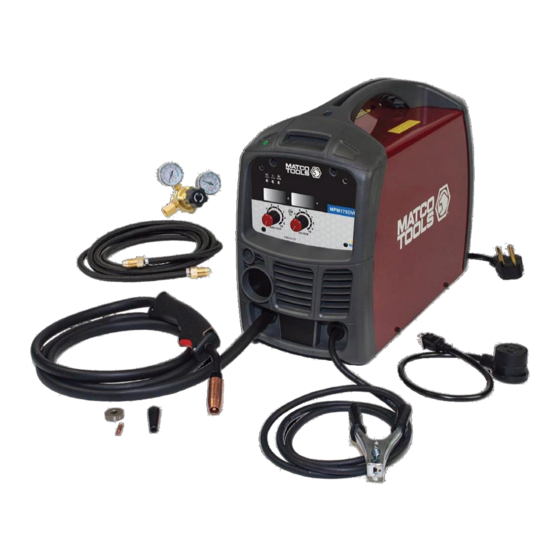
- Page 1 M P M 1 7 5 DV I OWNER’S MANUAL 11/2018 WARNING: Read carefully and understand all ASSEMBLY AND OPERATION INSTRUCTIONS before operating. Failure to follow the safety rules and other basic safety precautions may result in serious personal injury. 18115445-12...
- Page 2 Limited to the warranty periods below, MATCO TOOLS will repair or replace the item under warranty that fails due to defects in material and workmanship. MATCO TOOLS must be notified within 30 days of the failure, so as to provide instructions on how to proceed with the repair of your welder and warranty claim processing.
-
Page 3: General Safety Rules
GENERAL SAFETY RULES WARNING: Read and understand all instructions. Failure to follow all instructions listed below may result in serious injury or death. CAUTION: Do not allow persons to operate or assemble this unit until they have read this manual and have developed a thorough understanding of how this unit works. WARNING: The warnings, cautions, and instructions discussed in this instruction manual cannot cover all possible conditions or situations that could occur. - Page 4 -Connect ground lead as close to the area being welded as possible to ensure a good ground. -Do not allow any body part to come in contact with the welding wire if you are in contact with the material being welded, ground or electrode from another welder. -Do not weld if you are in an awkward position.
- Page 5 UV and IR Arc Rays The welding arc produces ultraviolet (UV) and infrared (IR) rays that can cause injury to your eyes and skin. Do not look at the welding arc without proper eye protection. -Always use a helmet that covers your full face from the neck to top of head and to the back of each ear.
- Page 6 Electromagnetic Field -Electromagnetic fields can interfere with various electrical and electronic devices such as pacemakers. -Consult your doctor before using any electric arc welder or cutting device. -Keep people with pacemakers away from your welding area when welding. -Do not wrap cable around your body while welding. -Wrap MIG gun and ground cable together whenever possible.
-
Page 7: Technical Specifications
It features infinite wire feed speed control and voltage control, giving you total control to tune in the arc you want. The MPM175DVI also features a cooling fan and thermal overload protection to help protect your investment. The Inverter Technology is evident from the moment you take this unit out of the box. -
Page 8: Installation
POWER INDICATOR LIGHT In the “OFF” position no power is being supplied to the torch. In the “ON” position power is supplied to the main transformer and control circuit. PROTECTION INDICATOR LIGHT If the duty cycle of the welder is exceeded, the internal temperature will exceed safe temperatures and the machine will shut down. - Page 9 Do not remove grounding prong or alter the plug in any way. Use only the supplied adapter between the plasma cutter's power cord and the power source receptacle. Make sure the POWER switch is OFF when connecting your welder’s power cord directly to a properly grounded 230 VAC, 60 HZ, Single Phase, 50 Amp input power supply.
- Page 10 g. Reinstall the Drive Roller Cap and lock in place by turning it clockwise. h. Close the door to the welder drive compartment. 5. INSTALL THE WIRE a. Select welding wire - We recommend the usage of .030 Wire on this unit. However, .023 - .035 wire may be used.
- Page 11 Contact Flux Core Nozzle Nozzle b. Make sure the proper groove on the drive roller is in place for the wire installed. If not, change the drive roller as described in Section 4 above. c. Remove the packaging from the spool of wire and then identify the leading end of the wire secured on the edge of the spool.
- Page 12 8 Inch 4 Inch Setting the wire spool tension. a) Turn the spool of wire with one hand. b) Increase the spool tension by tightening (turn clockwise) the wing nut while turning the spool. Turn the spool while tightening the wing nut until the spool slows down and you feel a slight drag.
- Page 13 -The welding wire is electrically hot when the power is on and the torch trigger is activated. p. Set the WIRE SPEED control to the middle of the wire speed range. q. Straighten the MIG torch cable and pull the trigger in the gun handle to feed the wire through the torch assembly.
- Page 14 d. Connect one end of the gas hose to the gas hose connection on the back of the welder. e. Connect the other end of the gas hose to the gas hose connection on the supplied regulator/flow gauge. Before installing the regulator, it is good practice to make certain no debris is in the gas bottle connection.
- Page 15 should be heard when the trigger is activated. No gas flow will result in a harsh arc with excessive spatter, a smooth weld bead will be difficult to obtain. Avoid unnecessary gas loss by closing the tank valve when finished welding. 6.7 Gas selection Different materials require different shielding gas when MIG welding, refer to the set up chart inside the wire feed compartment.
-
Page 16: Mig Operation
MIG OPERATION High voltage danger from power source! Consult a qualified electrician for proper installation of receptacle. This welder must be grounded while in use to protect the operator from electrical shock. Do not remove grounding prong or alter the plug in any way. Use only the supplied adapter between the plasma cutter's power cord and the power source receptacle. - Page 17 6. DISTANCE FROM THE WORK PIECE - If the nozzle is held off the work piece, the distance between the nozzle and the work piece should be kept constant and should not exceed 1/4 inch or the arc may begin sputtering, signaling a loss in welding performance. 7.
- Page 18 ELECTRIC SHOCK CAN CAUSE INJURY OR DEATH! To prevent ELECTRIC SHOCK, do not perform any welding while standing, kneeling, or lying directly on the grounded workpiece. 8.1 Moving the torch Torch travel refers to the movement of the torch along the weld joint and is broken into two elements: Direction and Speed.
- Page 19 8.3 Welding position FLAT POSITION is easiest of the welding positions and is most commonly used. It is best if you can weld in the flat position if at all possible as good results are easier to achieve. HORIZONTAL POSITION is performed very similarly to the flat weld except that angle B (see HOLDING THE TORCH) is such that the wire, directed more toward the metal above the weld joint is to help prevent the weld puddle from running downward while still allowing slow enough travel speed.
- Page 20 OVERHEAD POSITION is the most difficult welding position. Angle A (see HOLDING THE TORCH) should be maintained at 60 degrees. Maintaining this angle will reduce the chances of molten metal falling into the nozzle. Angle B should be held at zero degrees so that the wire is aiming directly into the weld joint.
- Page 21 8.5 Spot welding There are three methods of spot welding: Burn-Through, Punch and Fill, and Lap. Each has advantages and disadvantages depending on the specific application as well as personal preference. 1. The BURN-THROUGH METHOD welds two overlapped pieces of metal together by burning through the top piece and into the bottom piece.
-
Page 22: Maintenance
8.6 SPOT WELDING INSTRUCTIONS 1. Select the wire diameter and heat setting recommended above for the method of spot welding you intend to use. 2. Tune in the wire speed as if you were going to make a continuous weld. 3. - Page 23 MAIN CIRCUIT CHART Page of 26 18115445-12...
-
Page 24: Spare Parts List
SPARE PARTS LIST Page of 26 18115445-12... - Page 25 DOOR LATCH 105200009 WIRE SPOOL HOLDER 105200242 WELD OUTPUT CONNECTOR - POSITIVE 105200241 WELD OUTPUT CONNECTOR - NEGATIVE 165200027 DOOR 165200033 WELD SET-UP CHART MPM175DVI 105200002 DRIVE ROLLER 105200198 WIRE DRIVE ASSEMBLY 105200263 CENTER PANEL 105800042 FRONT PANEL PC BOARD 105200066...
- Page 26 Distributed by Matco Tool 4403 Allen Road Stow OH 44224 w w w . m a t c o t o o l s . c o m Made in China to Matco specifications Page of 26 18115445-12...
Need help?
Do you have a question about the MPM175DVI and is the answer not in the manual?
Questions and answers