Table of Contents
Advertisement
Quick Links
Advertisement
Table of Contents

Related Manuals for Matco Tools MPM141


Summary of Contents for Matco Tools MPM141
- Page 1 MPM141 INVERTER DC WIRE FEED WELDER OWNER’S MANUAL 09/2019 WARNING: Read carefully and understand all ASSEMBLY AND OPERATION INSTRUCTIONS before operating. Failure to follow the safety rules and other basic safety precautions may result in serious personal injury. 1910308-12...
- Page 2 Limited to the warranty periods below, MATCO TOOLS will repair or replace the item under warranty that fails due to defects in material and workmanship. MATCO TOOLS must be notified within 30 days of the failure, to provide instructions on how to proceed with the repair of your welder and warranty claim processing.
-
Page 3: General Safety Rules
will keep the welder secure and prevent it from GENERAL SAFETY RULES tipping over or falling. WARNING: Read and understand all 1.2 Your Welder’s Condition instructions. Failure to follow all instructions -Check ground cable, power cord and welding listed below may result in serious injury or death. cable to be sure the insulation is not damaged. - Page 4 Warning safety data sheet for the manufacturer’s Electrical Shock instructions. -Do not weld near materials that will emit toxic Electric arc welders can produce a fumes when heated. Vapors from cleaners, shock that can cause injury or death. sprays and degreasers can be highly toxic when Touching electrically live parts can cause fatal heated.
- Page 5 -Keep a fire extinguisher close in the case of fire. -Wear garments that are oil-free with no pockets Shielding Gas Cylinders Can or cuffs that will collect sparks. Explode -Do not have on your person any items that are combustible, such as lighters or matches. High pressure cylinders can explode if -Keep work lead connected as close to the weld damaged, so treat them carefully.
-
Page 6: Technical Specifications
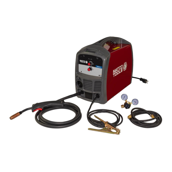
A smaller transformer means lower overall weight. The MPM141 is ideal for use when welding materials from 22 gauge to 1/8” and is ideal for the home hobbyist, auto repair, farm and ranch and light industrial applications. - Page 7 Work Alarm Power Power Light Light Indicator Cord Wire Feed Speed Control Welding Inert Gas Voltage Control Regulator Torch Inert Gas Hose Ground Cable Flux Core Nozzle and And Clamp Contact Tips POWER INDICATOR LIGHT wire feed compartment for initial adjustment In the “OFF”...
-
Page 8: Installation
welding. It protects the contact tip adapter from 3. INSTALL THE WIRE ROLLER - The wire spatter and debris during the flux core welding process. The extra contact tips are **Tweco® 11- roller has been factory installed. However, check to make certain the correct wire groove 30 style tips used when using .030 welding wire. - Page 9 4. INSTALL THE WIRE 4.1 Select welding wire - We recommend 4.2.1 Remove the nozzle and contact the usage of .030 wire on this unit. tip from the end of the torch assembly. However, .023 - .035 wire may be used. Both four-inch and eight-inch wire spools Contact Flux Core...
- Page 10 wing nut until the spool slows down and you feel a slight drag. Stop tightening the wing nut, you may need to repeat these steps until proper spool tension is achieved. NOTE: - If TOO MUCH tension is applied to the wire spool, the wire will slip on the drive roller or will not be able to feed at all.
- Page 11 4.2.14 NOW YOU CAN LET GO OF coming out of the end of the torch does not THE WIRE. come in contact with the work piece, ground 4.2.15 Plug in the welder power clamp, or any grounded material during the cord and turn the welder ON.
-
Page 12: Operation
connection. Refer to the polarity setting heard when the trigger is activated. No gas flow label inside the wire compartment. will result in a harsh arc with excessive spatter, 6.2 Connect one end of the gas hose to a smooth weld bead will be difficult to obtain. the gas hose connection on the back of the Avoid unnecessary gas loss by closing the tank welder. - Page 13 1. POWER SWITCH penetration will increase. If angle A is The power switch supplies electrical current to decreased, penetration will decrease also. the welder. Whenever the power switch is in the 5.2. Angle B can be varied for two reasons: ON position, the welding circuit is activated.
- Page 14 you will be welding. It should be equal to or workpiece. greater than the thickness of the actual 8.1 Moving the torch work piece, and free of oil, paint, rust, etc. Torch travel refers to the movement of the 7.2 Select a heat setting. torch along the weld joint and is broken 7.3 Hold the torch in one hand.
- Page 15 The STRINGER BEAD is formed by HORIZONTAL POSITION is performed traveling with the torch in a straight line very similarly to the flat weld except that while keeping the wire and nozzle angle B (see HOLDING THE TORCH) is centered over the weld joint. See following such that the wire, directed more toward figure.
- Page 16 a strong joint. The following figure will show the sequence of laying multiple pass beads into a T fillet joint and a lap fillet joint. 8.4 Multiple pass welding Butt Weld Joints: When butt welding thicker materials; you will need to prepare the edges of the material to be joined by grinding a bevel on the edge of one or both pieces of the metal being joined.
- Page 17 metal build-up and minimal 8.6 SPOT WELDING INSTRUCTIONS penetration is acceptable. Always 8.6.1. Select the wire diameter and select the HIGH heat setting with the heat setting recommended above for burn-through method and tune in the the method of spot welding you intend wire speed prior to making a spot to use.
-
Page 18: Maintenance
MAINTENANCE • Maintain your welder. It is recommended that the general condition of any welder be examined before it is used. Keep your welder in good repair by adopting a program of conscientious repair and maintenance. Have necessary repairs made by qualified service personnel. •... -
Page 19: Diagram & Parts List
LATCH 125200077 165200051 FAN SUPPORT 165200016 BACK PLASTIC PANEL 105200441 GAS CONNECTOR 105200266 GAS HOLDER 105800002 POWER CORD 105200046 SWITCH Replacement parts can be ordered through your Matco Tools Distributor For technical questions, call 855-920-2399. 1910308-12 Page 19 of 20... - Page 20 Distributed by Matco Tool 4403 Allen Road Stow OH 44224 w w w . m a t c o t o o l s . c o m Made in China 1910308-12 Page 20 of 20...
Need help?
Do you have a question about the MPM141 and is the answer not in the manual?
Questions and answers