Table of Contents
Advertisement
Quick Links
Advertisement
Table of Contents

Related Manuals for Matco Tools MP240DVI


Summary of Contents for Matco Tools MP240DVI
- Page 1 MP240DVI OWNER’S MANUAL 7/2017 WARNING: Read carefully and understand all ASSEMBLY AND OPERATION INSTRUCTIONS before operating. Failure to follow the safety rules and other basic safety precautions may result in serious personal injury. 1703088-12MA...
- Page 2 Limited to the warranty periods below, MATCO TOOLS will repair or replace the item under warranty that fails due to defects in material and workmanship. MATCO TOOLS must be notified within 30 days of the failure, so as to provide instructions on how to proceed with the repair of your welder and warranty claim processing.
-
Page 3: General Safety Rules
GENERAL SAFETY RULES WARNING: Read and understand all instructions. Failure to follow all instructions listed below may result in serious injury or death. CAUTION: Do not allow persons to operate or assemble this unit until they have read this manual and have developed a thorough understanding of how this unit works. WARNING: The warnings, cautions, and instructions discussed in this instruction manual cannot cover all possible conditions or situations that could occur. - Page 4 - Keep welder in the off position when not in use. - Connect ground lead as close to the area being welded as possible to ensure a good ground. - Do not allow any body part to come in contact with the welding wire if you are in contact with the material being welded, ground or electrode from another welder.
- Page 5 UV and IR Arc Rays The welding arc produces ultraviolet (UV) and infrared (IR) rays that can cause injury to your eyes and skin. Do not look at the welding arc without proper eye protection. -Always use a helmet that covers your full face from the neck to top of head and to the back of each ear.
- Page 6 Electromagnetic Field - Electromagnetic fields can interfere with various electrical and electronic devices such as pacemakers. - Consult your doctor before using any electric arc welder or cutting device. - Keep people with pacemakers away from your welding area when welding. - Do not wrap cable around your body while welding.
-
Page 7: Technical Specifications
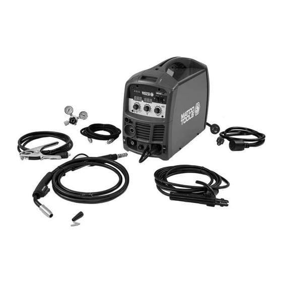
31 lb. DESCRIPTION The MATCO TOOLS MP240DVI is a dual voltage portable DC inverter wire feed welder capable of welding with solid wire (with shielding gas) or with flux core wire. It comes ready to accept part number MATEZFSG2 Optional Spool Gun for welding aluminum. This machine also has smooth DC stick capabilities and the ability to perform lift start DC TIG welding on steel and stainless steel materials with part number MATACTT1, the optional TIG Torch. - Page 8 Spool Gun/ Spot Timer Voltage MIG Torch/Stick Indicator On/Off Setting Welding Selector Lights Digital Meters Spot Time Wire Speed Adjustment & Amperage Control Regulator/ Flowgauge Hose Electrode Holder And Cable Ground Cable And MIG Torch Clamp POWER INDICATOR LIGHT In the “OFF” position no power is being supplied to the torch. In the “ON” position power is supplied to the main transformer and control circuit.
- Page 9 SPOOL GUN/MIG TORCH/STICK WELDING SELECTOR When normal MIG welding, this switch should be turned in “MIG” position. When using the spool gun, the switch should be in “spool gun” position. When DC stick welding, the switch will be in the "stick" position. SPOT TIME ADJUSTMENT The Spot Time Adjustment allows you to set a time from 0.1 to 9.9 seconds for consistent spot welds.
- Page 10 Socket 5-Pin Trigger Negative (-) Receptacle Weld Output Connection Positive (+) Weld Output Connection Weld Power Cable 1.4 Connect the 5-Pin trigger connection on the MIG torch to the 5-Pin trigger receptacle on the front panel. Connect the ground cable to the Negative (-) weld output connection for MIG welding. If welding with self shielded flux core, connect the ground cable to the Positive (+) weld output connection and move the Weld Power Cable to the Negative (-) weld output connection.
- Page 11 2.3 We recommend removing the MIG torch when the Spool Gun is connected to avoid accidental arcing. Loosen the wing nut retaining bolt and slide the MIG torch out of the front of the machine. Disconnect the 5-Pin trigger connection on the front of the machine. 2.4 Carefully slide the gas connector (1) and the weld power connection (2) through the weld cable access opening in the front of the machine.
-
Page 12: Installation
2.9 Make certain the SPOOL GUN/MIG TORCH/STICK SELECTOR on the front panel is switched into the SPOOL GUN position. 3. DC STICK WELDING ASSEMBLY Be aware that the ELECTRODE HOLDER will be electrically HOT when the Input Power Switch on the welder is turned on. - Page 13 1. POWER REQUIREMENT 230V - AC single phase 230V (200-240V) 50/60 Hz fused with a 50 amp time delayed fuse or circuit breaker is required. DO NOT OPERATE THIS UNIT if the ACTUAL power source voltage is less than 215 volts AC or greater than 240 volts AC. 2.
- Page 14 e. Based on the wire diameter select the correct groove. When installing the drive roller, the number stamped on the drive roller for the wire size you are using should be facing you. Push the Drive Roller onto the Drive Roller Shaft. f.
- Page 15 g. The welder can use either 4-inch or 8-inch spools. See the following figure for additional reference. The wing nut controls the tension on the spool. 8-Inch 4-Inch h. Setting the wire spool tension. a) Turn the spool of wire with one hand. b) Increase the spool tension by tightening (turn clockwise) the wing nut while turning the spool.
- Page 16 -Make certain that the welding wire is actually going into the torch liner. If not, the wire will jam up in the mechanism. m. Line the wire up with the correct groove in the drive roller. Place the drive tension arm back above the drive roller.
-
Page 17: Gas Installation
7. GAS INSTALLATION Shielding gas cylinders and high pressure cylinders can explode if damaged, so treat them carefully. Never expose cylinders to high heat, sparks, open flames, mechanical shocks or arcs. Do not weld on the cylinder. Always secure cylinder upright to a cart or stationary object. - Page 18 (7) Gas Cylinder g. Open the Gas Bottle Valve on the cylinder of gas. h. Turn the Gas Flow Adjuster on the regulator so that the gas flow rate is set at approximately 20 CFM. Make certain you are reading the correct scale on the gauge. NOTE: Slowly open the cylinder valve by turning it counterclockwise until the cylinder pressure gauge registers on the first gauge of the regulator.
-
Page 19: Mig Operation
MIG OPERATION • High voltage danger from power source! Consult a qualified electrician for proper installation of receptacle. This cutter must be grounded while in use to protect the operator from electrical shock. • Do not remove grounding prong or alter the plug in any way. Use only the supplied adapter between the welder's power cord and the power source receptacle. -
Page 20: Welding Techniques
6. DISTANCE FROM THE WORK PIECE - If the nozzle is held off the work piece, the distance between the nozzle and the work piece should be kept constant and should not exceed 1/4 inch or the arc may begin sputtering, signaling a loss in welding performance. 7. - Page 21 ELECTRIC SHOCK CAN CAUSE INJURY OR DEATH! To prevent ELECTRIC SHOCK, do not perform any welding while standing, kneeling, or lying directly on the grounded work piece. 8.1 Moving the torch Torch travel refers to the movement of the torch along the weld joint and is broken into two elements: Direction and Speed.
- Page 22 8.3 Welding position FLAT POSITION is easiest of the welding positions and is most commonly used. It is best if you can weld in the flat position if at all possible as good results are easier to achieve. HORIZONTAL POSITION is performed very similarly to the flat weld except that angle B (see HOLDING THE TORCH) is such that the wire, directed more toward the metal above the weld joint is to help prevent the weld puddle from running downward while still allowing slow enough travel speed.
- Page 23 should be maintained at 60 degrees. Maintaining this angle will reduce the chances of molten metal falling into the nozzle. Angle B should be held at zero degrees so that the wire is aiming directly into the weld joint. If you experience excessive dripping of the weld puddle, select a lower heat setting. Also, the weave bead tends to work better than the stringer.
- Page 24 8.5 Spot welding There are three methods of spot welding: Burn-Through, Punch and Fill, and Lap. Each has advantages and disadvantages depending on the specific application as well as personal preference. 1. The BURN-THROUGH METHOD welds two overlapped pieces of metal together by burning through the top piece and into the bottom piece.
-
Page 25: Spot Welding Instructions
8.6 SPOT WELDING INSTRUCTIONS 1. Select the wire diameter and heat setting recommended above for the method of spot welding you intend to use. 2. Tune in the wire speed as if you were going to make a continuous weld. 3. -
Page 26: Ground Clamp Connection
Based on different welding positions, there are different welding joints. See following images for more information. 2. GROUND CLAMP CONNECTION Clear any dirt, rust, scale, oil or paint on the ground clamp. Make certain you have a good solid ground connection. A poor connection at the ground clamp will waste power and heat. Make sure the ground clamp touches the metal. - Page 27 4.1. When proper rod is used: 4.1.a. The bead will lay smoothly over the work without ragged edges 4.1.b. The base metal puddle will be as deep as the bead that rises above it 4.1.c. The welding operation will make a crackling sound similar to the sound of eggs frying 4.2.
- Page 28 work piece should be between 10 and 30 degrees. This will allow for good penetration, with minimal spatter. 6.2 Striking the arc EXPOSURE TO A WELDING ARC IS EXTREMELY HARMFUL TO THE EYES AND SKIN! Prolonged exposure to the welding arc can cause blindness and burns. Never strike an arc or begin welding until you are adequately protected.
- Page 29 The weave bead: Used when you want to deposit metal over a wider space than would be possible with a stringer bead. It is made by weaving from side to side while moving with the electrode. It is best to hesitate momentarily at each side before weaving back the other way. 6.4 Welding position Flat position: It is easiest of the welding positions and is most commonly used.
- Page 30 chemical reaction. The burning coating, however, forms slag. The slag formation appears as an accumulation of dirty metal scale on the finished weld. Slag should be removed by using a chipping hammer. PEENING THE SLAG FROM A WELD JOINT CAUSES SMALL CHIPS OF METAL TO FLY THROUGH THE AIR! Metallic chips flying through the air can cause eye injury or injury to other parts of the head, hands or exposed portions of the body.
-
Page 31: Maintenance
8. Follow these steps for striking an arc while TIG welding. a. Open the shielding gas valve on the torch handle to begin gas flow. b. Rest the TIG torch nozzle on the work piece making sure to not touch the installed tungsten electrode. -
Page 32: Troubleshooting
TROUBLESHOOTING SYMPTOM POSSIBLE CAUSE CORRECTIVE ACTION Unit does not power up Unit is not plugged in Plug in unit Input power circuit breaker not on Reset input power circuit breaker The main power switch is not Replace main power switch working Protection indicator is on The internal temperature is too high. - Page 33 MAIN CIRCUIT CHART Page of 36 1703088-12MA...
-
Page 34: Diagram & Parts List
DIAGRAM & PARTS LIST Reference # Part# Description Qty. 105200044 HANDLE 165200027 ENCLOSURE 165200028 MATCO WELDER HELP LABEL 105200041 MIG WARNING LABEL 165200028 WELDER HELP LABEL 105200045 GAS CONNECTOR 105200046 POWER SWITCH 105200047 GAS VALVE 105200048 BACK PANEL 105200049 105200050 MAIN PC BOARD 105200051 CONTROL PC BOARD... - Page 35 INLET GUIDE 105200086 QUICK CONNECTOR WITH GAS HOSE 105200054 BOTTOM 105200055 MIG CONNECTOR 165200262 PLASTIC FRONT PANEL BEZEL 165200029 FRONT PANEL DECAL MP240DVI 105200057 WELD POWER CABLE 105200058 WELD POWER CONNECTOR 105200059 TRIGGER RECEPTACLE 105200060 GROUND CABLE AND CLAMP 105200069...
- Page 36 Distributed by Matco Tools 4403 Allen Road Stow OH 44224 w w w . m a t c o t o o l s . c o m Made in China to Matco specifications Page of 36 1703088-12MA...
Need help?
Do you have a question about the MP240DVI and is the answer not in the manual?
Questions and answers