Table of Contents
Advertisement
Quick Links
Part # TG2010
2015-06
Processes
TIG(GTAW) Welding
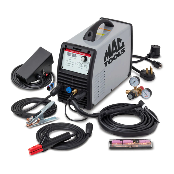
110-240VAC Arc Welding machine
INVERTER AC/DC PULSED TIG WELDER
TG2010 AC/DC PFC
OPERATOR'S MANUAL
2015.06
IMPORTANT: Read this Owner's Manual Completely before attempting to use this
equipment. Save this manual and keep it handy for quick reference. Pay particular
attention to the safety instructions we have provided for your protection. Contact your
.
distributor if you do not fully understand this manual.
Advertisement
Table of Contents
Troubleshooting

Related Manuals for Matco Tools TG2010


Summary of Contents for Matco Tools TG2010
- Page 1 Part # TG2010 2015-06 Processes TIG(GTAW) Welding 110-240VAC Arc Welding machine INVERTER AC/DC PULSED TIG WELDER TG2010 AC/DC PFC OPERATOR’S MANUAL 2015.06 IMPORTANT: Read this Owner’s Manual Completely before attempting to use this equipment. Save this manual and keep it handy for quick reference. Pay particular attention to the safety instructions we have provided for your protection.
-
Page 2: Table Of Contents
CONTENT SECTION 1: SAFETY ........................ 1 1.1 S ......................1 IGNAL XPLANATION 1.2 A ....................... 1 ELDING AMAGE 1.3 E .............. 4 XPLANATION OF LECTRIC AND AGNETIC IELDS SECTION 2: INTRODUCTION ....................5 TG2010AC/DC I ..................5 NFORMATION 2.2 M ...................... -
Page 3: Section 1: Safety
OPERATION 1 SAFETY 1.1 Signal and Hazard Explanation The above signals mean Warning, Notice, and Running Parts Safe operation is simple after taking several necessary protection measures. The protection measures and hazard explanations are listed in the following pages. ... - Page 4 SAFETY welded. The connection should be as close as possible to the area being welded. Maintain the electrode holder, work clamp, welding cable and welding machine in good, safe operating condition. Replace any damaged insulation. Never dip the electrode in water for cooling. ...
- Page 5 SAFETY Be careful to avoid hot spatter or metal caused from the arc rays. Use a shield with the proper filter and cover plates to protect your eyes from sparks and the rays of the arc when welding or observing open arc welding. WELDING SPARKS can cause fire or explosion.
-
Page 6: Explanation Of Electric And Magnetic Fields
SAFETY Connect the work cable to the work as close to the welding area as practical. Work cables connected to the building framework or other locations away from the welding area increase the possibility of the welding current passing through lifting chains, crane cables or other alternate circuits. -
Page 7: Section 2: Introduction
Thus, it is known for being portable, small in size, light weight, and having low consumption. The parameters of TG2010 on the front panel all can be adjusted with a single control knob. The parameters include, start current, crater arc current, welding current, base current, duty ratio, upslope time, downslope time, pre-gas, post-gas, pulse frequency, AC frequency, balance, hot start, arc force and arc length etc. - Page 8 SUMMARY Machine Welding Functions ⚫ DC MMA (STICK electrode welding for ferrous metals) ⚫ DC TIG (TIG welding for ferrous metals) ⚫ DC Pulse TIG (TIG with pulsed power for welding ferrous metals) ⚫ AC MMA (STICK electrode welding for aluminum metals) ⚫...
-
Page 9: Working Principle
SUMMARY TG2010 welding machine is suitable for all positions welding for various plates made of stainless steel, carbon steel, alloyed steel, titanium, aluminum, magnesium, cuprum, etc. It can be used for pipe installment, mold mend, petrochemical, architecture design, car repair, bicycle repair, common manufacturing and more. -
Page 10: Volt-Ampere Characteristic
SUMMARY 2.4 Volt-Ampere Characteristic The TG2010 AC/DC welding machine has an excellent volt-ampere characteristic as shown in the following figure. The relation between the conventional rated loading voltage U and the conventional welding current I is as follows: ≤600A,U >600A,U When I =10 + 0.04I... -
Page 11: Section 3: Installation And Adjustment
OPERATION 3 Installation and Adjustment 3.1 Parameters TG2010 AC/DC PFC Parameters Input power 1~220±10%,50Hz 1~110±10%,50Hz Rated input current 20/18(AC/DC 30/27(AC/DC 29/33(AC/DC 34/39(AC/DC MMA) (A) TIG) MMA) TIG) Rated input power 4.5/3.9(AC/DC 7/5.7(AC/DC 3.4/3.7(AC/DC 3.8/4.3 (AC/DC MMA) (KW) TIG) MMA) TIG)... -
Page 12: Duty Cycle & Over Heat
SET-UP, OPERATION & TROUBLSHOOTING 3.2 Duty cycle & over heat The letter “X” stands for duty cycle, which is defined as the proportion of the time that a machine can work continuously within a certain time (10 minutes). The rated duty cycle means the proportion of the time that a machine can work continuously within 10 The relation of the welding current and... -
Page 13: Power Supply Input Connection
SET-UP, OPERATION & TROUBLSHOOTING 3.4 Power supply input connection The TG2010 AC/DC PULSE PFC welding machine features electronic switching power supply allowing it to be connected to any 115-240VAC, 1-Phase LINE power outlet. 208-240VAC LINE CONNECTION: Machine is provided with NEMA 6-50P LINE Service cord to be plugged into any 6-50R outlet with 208-240VAC, single-phase power and 50-amp circuit breaker. -
Page 14: Machine Operational Layout
SET-UP, OPERATION & TROUBLSHOOTING 3.5 Machine operational layout Positive output: Socket with positive polarity output. Negative output: Socket with negative polarity output. Control output: Socket to torch or foot pedal control wire.(Lead 8 - lead 9 are trigger) Shield gas output: Brass male fitting to connect gas input hose of torch. Power switch: Controls input power ON/OFF to the welding machine Power source input: Power cord service cable with input power plug... - Page 15 SET-UP, OPERATION & TROUBLSHOOTING 3.6 Electrode / Torch polarity connections(MMA) ⚫ DC POSITIVE CONNECTION (DCEP): Work-piece is connected to the positive (+) socket of welding machine, and welding torch is connected to the negative (-) socket. Most common TIG and MMA (Stick) welding connection: Torch to negative (-) ⚫...
-
Page 16: Foot Pedal Control
SET-UP, OPERATION & TROUBLSHOOTING 3.7 Foot pedal switch control ● Once the foot pedal cable is inserted into control-socket on front panel of welder, it will identify the pedal switch. Only 2T/4T modes should be selected when foot pedal operation is desired. -
Page 17: Section 4: Operation
Once parameters for a particular welding JOB have been set, push to save in memory to recall. The illustration below shows an overview of the TG2010 control panel as an example. You will find a detailed description of these settings in the following section. - Page 18 SET-UP, OPERATION & TROUBLSHOOTING (3) Trigger mode selection (TIG only) (4) TIG parameter settings (5) AC parameter settings (6) MMA stick electrode parameter settings...
-
Page 19: Argon Arc Welding Operation
SET-UP, OPERATION & TROUBLSHOOTING 4.2 Argon Arc Welding Operation 4.2.1 TIG welding(4T operation) The START and END current and can be pre-set to compensate for crater that appears at the beginning and end of the welding making 4T ideal for aluminum and medium thickness plates. -
Page 20: Tig Welding (2T Operation)
OPERATION 4.2.2 TIG welding (2T operation) This function, without the adjustment of start current and crater current, is ideal for tack welding、transient welding and thin plate welding. I(A) Welding current Is Loosen the welding gun switch The setting base current Ib Arc is Arc is Press and hold the welding... -
Page 21: Tig Welding (Repeat)
SET-UP, OPERATION & TROUBLSHOOTING 4.2.3 TIG welding (Repeat) This function only works with a triggered gun; it will not function with foot pedal. This welding mode is ideal for working back and forth between two metals of varying characteristics. (Thick and thin, wide or narrow seam, deep or flat, etc.) •... - Page 22 SET-UP, OPERATION & TROUBLSHOOTING Torch & earth clamp checklist: ⚫ Check welding cable machine connections are twist-locked in place and gas fittings are secure; otherwise there may be malfunction such as ignition spark, gas leakage, and unstable arc. ⚫ Check that there is enough shield gas in the cylinder and that regulator is set correctly, you can test the electromagnetic gas valve through the switch on the front panel.
-
Page 23: Welding Parameters
SET-UP, OPERATION & TROUBLSHOOTING 4.4 Welding Parameters 4.4.1 Joint forms in TIG/MMA lap joint coner joint T joint butt joint 4.4.2 The explanation of welding quality The relation of welding area color & protect effect of stainless steel Welding area argent , blue red-grey... - Page 24 SET-UP, OPERATION & TROUBLSHOOTING Gas nozzle and the shield gas flow rate DC positive connection Welding current Gas nozzle Gas flow Gas nozzle Gas flow range/A diameter/mm rate/L·min diameter/mm rate/L·min 10~100 4~9.5 4~5 8~9.5 6~8 101~150 4~9.5 4~7 9.5~11 7~10 151~200 6~13 6~8...
- Page 25 SET-UP, OPERATION & TROUBLSHOOTING Corner 115~145 joint Butt joint 150~225 Corner 175~250 joint Notice: the above parameters originate from《Welding Dictionary》P150, Volume 1 of Edition 2. Parameters of piping back sealing welding for mild steel (DCEP) Piping Tungsten Welding Argon Welding Gas nozzle Welding diamet...
-
Page 26: Operation Environment
SET-UP, OPERATION & TROUBLSHOOTING 150~ - 2~3 8~12 8~12 180~ - 10~15 8~12 180~ - 3~4 10~15 10~12 240~ - 16~20 14~16 260~ 4~5 16~20 14~16 100~ 280~ V-groove butt 4~5 16~20 14~16 welding 150~ 300~ 4~5 5~6 18~22 16~20 180~... -
Page 27: Section 5: Maintenance & Troubleshooting
SET-UP, OPERATION & TROUBLSHOOTING 5 Maintenance & Troubleshooting 5.1 Maintenance In order to guarantee that arc welding machine works high-efficiently and in safety, it must be maintained regularly so as to lengthen service life of arc welding machine. Maintenance items in detail are in the following table. ●... -
Page 28: Troubleshooting
SET-UP, OPERATION & TROUBLSHOOTING wrapped up, insulated or changed. Use dry compressed air to clean and remove dusts on radiator, main voltage transformer, inductance coils, IGBT module, the fast recover diodes and PCB’s. Monthly Check the cable lugs on arc welding machine, if loose, please screw down exam securely. - Page 29 SET-UP, OPERATION & TROUBLSHOOTING Troubles Reasons Solution fan doesn’t work The fan motor damaged Change fan Turn on the power source, the No power supply input Check whether there is power supply power lamp is not on, and fan The fuse inside the machine damaged Change it (3A) doesn’t work The number on the display is...
- Page 30 SET-UP, OPERATION & TROUBLSHOOTING Troubles Reasons Solution The min value displayed isn’t accordant Adjust potentiometer Imin on the with the actual value. (Please refer to The welding current displayed power board. §3.1) isn’t accordant with the actual The max value displayed isn’t accordant value.
-
Page 31: Electrical Principle Drawing
SET-UP, OPERATION & TROUBLSHOOTING 5.3 Electrical principle drawing... -
Page 32: Exploded Parts Listing
PARTS & SERVICE 5.4 Exploded Parts Listing... - Page 33 PARTS & SERVICE 5.5 Exploded Torch Listing TG2010 comes standard with a compact WP17 air-cooled TIG torch rated 60% duty-cycle @ 150 amps (30% @ 200A) with 12.5’ direct-connect welding cable cover assembly with Dinse power plug and 5/8-18RHM gas line fitting. For extended duty-cycle operation or for...
Need help?
Do you have a question about the TG2010 and is the answer not in the manual?
Questions and answers