Table of Contents
Advertisement
Quick Links
Advertisement
Table of Contents

Related Manuals for Matco Tools MPM140I


Summary of Contents for Matco Tools MPM140I
- Page 1 MPM140I OWNER’S MANUAL 4/2017 WARNING: Read carefully and understand all ASSEMBLY AND OPERATION INSTRUCTIONS before operating. Failure to follow the safety rules and other basic safety precautions may result in serious personal injury. 1703081-12MA...
- Page 2 Limited to the warranty periods below, MATCO TOOLS will repair or replace the item under warranty that fails due to defects in material and workmanship. MATCO TOOLS must be notified within 30 days of the failure, so as to provide instructions on how to proceed with the repair of your welder and warranty claim processing.
-
Page 3: General Safety Rules
GENERAL SAFETY RULES WARNING: Read and understand all instructions. Failure to follow all instructions listed below may result in serious injury or death. CAUTION: Do not allow persons to operate or assemble this unit until they have read this manual and have developed a thorough understanding of how this unit works. WARNING: The warnings, cautions, and instructions discussed in this instruction manual cannot cover all possible conditions or situations that could occur. - Page 4 -Connect ground lead as close to the area being welded as possible to ensure a good ground. -Do not allow any body part to come in contact with the welding wire if you are in contact with the material being welded, ground or electrode from another welder. -Do not weld if you are in an awkward position.
- Page 5 UV and IR Arc Rays The welding arc produces ultraviolet (UV) and infrared (IR) rays that can cause injury to your eyes and skin. Do not look at the welding arc without proper eye protection. -Always use a helmet that covers your full face from the neck to top of head and to the back of each ear.
-
Page 6: Technical Specifications
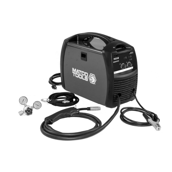
Electromagnetic Field -Electromagnetic fields can interfere with various electrical and electronic devices such as pacemakers. -Consult your doctor before using any electric arc welder or cutting device. -Keep people with pacemakers away from your welding area when welding. -Do not wrap cable around your body while welding. -Wrap MIG gun and ground cable together whenever possible. - Page 7 It features infinite wire feed speed control and voltage control giving you total control to tune in the arc you want. The MATCO TOOLS MPM140I also features a cooling fan and thermal overload protection to help protect your investment. The Inverter Technology is evident from the moment you take this unit out of the box.
- Page 8 POWER INDICATOR LIGHT In the “OFF” position no power is being supplied to the torch. In the “ON” position power is supplied to the main transformer and control circuit. PROTECTION INDICATOR LIGHT If the duty cycle of the welder is exceeded, the internal temperature will exceed safe temperatures and the machine will shut down.
-
Page 9: Installation
INSTALLATION 1. POWER REQUIREMENT - AC single phase 120V (110-120V) 60 HZ fused with a 20 amp time delayed fuse or circuit breaker is required. DO NOT OPERATE THIS UNIT if the ACTUAL power source voltage is less than 105 volts AC or greater than 132 volts AC. Electrical Shock ... - Page 10 without holding onto it or the wire spool will unspool itself. Put the end of the wire into the hole on the outside edge of the wire spool and bend it over to hold the wire in place. Remove the spool of wire from the drive compartment of the welder.
- Page 11 4.2.4 Place the spool on the spool hub so the wire will pull off the bottom of the spool. The welding wire should always come off the bottom of the spool into the drive mechanism. See following figure. 4.2.5 The welder can use either 4-inch or 8-inch spools. See the following figure for additional reference.
- Page 12 4.2.11 Line the wire up with the correct groove in the drive roller. Place the drive tension arm back above the drive roller. 4.2.12 Place the drive tension adjustment arm back in place. 4.2.13 Tighten (turn clockwise) the drive tension adjusting knob until the tension roller is applying enough force on the wire to prevent it from slipping in the drive rollers.
- Page 13 6.1 Polarity Changing - When MIG wire is used, shielding gas is required and the polarity on this unit needs to be electrode positive. 6.1.1 Electrode Positive for MIG Welding - The Weld Power Cable should be connected to the positive (+) weld output connection on the front of the machine.
- Page 14 6.6 Turn the Gas Flow Adjuster on the regulator so that the gas flow rate is set at approximately 20 CFM. Make certain you are reading the correct scale on the gauge. NOTE: Slowly open the cylinder valve by turning it counterclockwise until the cylinder pressure gauge registers on the first gauge of the regulator.
-
Page 15: Mig Operation
MIG OPERATION High voltage danger from power source! Consult a qualified electrician for proper installation of receptacle at the power source. This welder must be grounded while in use to protect the operator from electrical shock. If you are not sure if your outlet is properly grounded, have it checked by a qualified electrician. - Page 16 6. DISTANCE FROM THE WORK PIECE - If the nozzle is held off the work piece, the distance between the nozzle and the work piece should be kept constant and should not exceed 1/4 inch or the arc may begin sputtering, signaling a loss in welding performance. 7.
- Page 17 ELECTRIC SHOCK CAN CAUSE INJURY OR DEATH! To prevent ELECTRIC SHOCK, do not perform any welding while standing, kneeling, or lying directly on the grounded workpiece. 8.1 Moving the torch Torch travel refers to the movement of the torch along the weld joint and is broken into two elements: Direction and Speed.
- Page 18 8.3 Welding position FLAT POSITION is easiest of the welding positions and is most commonly used. It is best if you can weld in the flat position if at all possible as good results are easier to achieve. HORIZONTAL POSITION is performed very similarly to the flat weld except that angle B (see HOLDING THE TORCH) is such that the wire, directed more toward the metal above the weld joint is to help prevent the weld puddle from running downward while still allowing slow enough travel speed.
- Page 19 falling into the nozzle. Angle B should be held at zero degrees so that the wire is aiming directly into the weld joint. If you experience excessive dripping of the weld puddle, select a lower heat setting. Also, the weave bead tends to work better than the stringer. 8.4 Multiple pass welding Butt Weld Joints: When butt welding thicker materials, you will need to prepare the edges of the material to be joined by grinding a bevel on the edge of one or both pieces of the metal being joined.
- Page 20 8.5 Spot welding There are three methods of spot welding: Burn-Through, Punch and Fill, and Lap. Each has advantages and disadvantages depending on the specific application as well as personal preference. 1. The BURN-THROUGH METHOD welds two overlapped pieces of metal together by burning through the top piece and into the bottom piece.
-
Page 21: Maintenance
Maintain your MATCO TOOLS MPM140I. It is recommended that the general condition of any welder be examined before it is used. Keep your MATCO TOOLS MPM140I in good repair by adopting a program of conscientious repair and maintenance. Have necessary repairs made by qualified service personnel. - Page 22 MAIN CIRCUIT CHART Page of 26 1703081-12MA...
-
Page 23: Spare Parts List
SPARE PARTS LIST Page of 26 1703081-12MA... - Page 24 DOOR LATCH 105200009 WIRE SPOOL SUPPORT 105200242 WELD OUTPUT CONNECTOR - POSITIVE 105200241 WELD OUTPUT CONNECTOR - NEGATIVE 165200027 DOOR 165200020 WELD SET-UP CHART MPM140I 105200002 DRIVE ROLLER 105200198 WIRE DRIVE ASSEMBLY 105200263 CENTER PANEL 105200224 VOLTAGE POTENTIOMETER 105200187 INDICATOR...
- Page 25 Page of 26 1703081-12MA...
- Page 26 Distributed by Matco Tool 4403 Allen Road Stow OH 44224 w w w . m a t c o t o o l s . c o m Made in China to Matco specifications Page of 26 1703081-12MA...
Need help?
Do you have a question about the MPM140I and is the answer not in the manual?
Questions and answers