
Subscribe to Our Youtube Channel
Related Manuals for Zennio KLIC-DI SKY


Summary of Contents for Zennio KLIC-DI SKY
- Page 1 KLIC-DI SKY KNX Interface for Commercial A/C Units ZN1CL-KLIC-DI Application programme version: [2.0] User manual edition: [2.0]_a www.zennio.com...
-
Page 2: Table Of Contents
KLIC-DI SKY CONTENTS Contents ............................2 Document Updates ........................3 Introduction .......................... 4 KLIC-DI ........................... 4 Installation ........................5 Configuration......................... 8 Basic Control........................8 Advanced Functionality ....................8 Testing KLIC-DI from an IR remote ................12 ETS Parameterisation ......................13 Default Configuration .................... -
Page 3: Document Updates
KLIC-DI SKY DOCUMENT UPDATES Version Version Changes Changes Page(s) Page(s) Changes in the application programme: [2.0]_a • Improvement of the error handling. [1.14]_b Clarifications for a correct configuration. Changes in the application programme: • Compatibility with the new remote control of Daikin BRC1E53A7. -
Page 4: Introduction
KLIC-DI VRV, for industrial A/C systems with a variable refrigerant volume. KLIC-DI SKY, for other commercial A/C systems. Because of this bidirectional communication, the air conditioning unit can be controlled in the same manner as through its own controls, while the real status of the air-conditioning unit is monitored and periodically sent to the KNX bus to inform other devices. -
Page 5: Installation
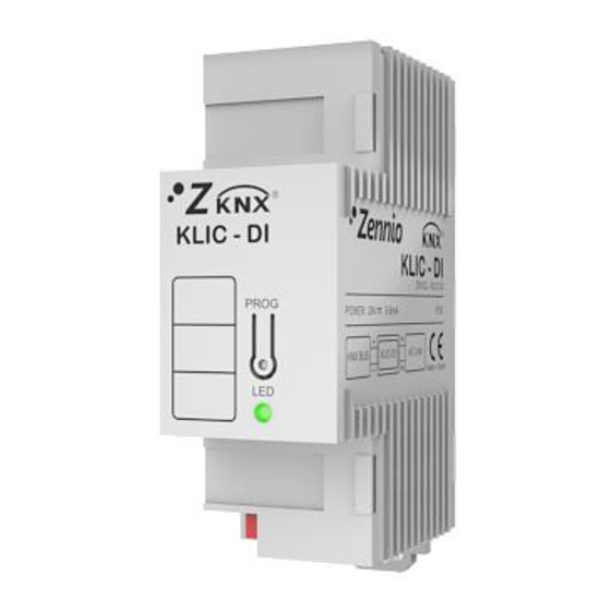
KLIC-DI SKY 1.2 INSTALLATION 1.- KNX Connector 2.- LED Indicator 3.- Programming Button 4.- Input Terminal for the Two-Wire Communication Cable. Figure 1. Element scheme KLIC-DI connects to the KNX bus via the corresponding built-in terminals (1). On the other hand, this device is connected to the internal PCB board of the A/C unit (P1/P2 connectors), using a 2-wire cable. - Page 6 KLIC-DI SKY device is under the programming or secure modes, this LED will also show react to the communication between KLIC-DI and the A/C unit, which may be particularly useful during the installation process. The meaning of the different colour components is explained next: ➢...
- Page 7 Reading the KLIC-DI installation note, available at the same website, is also encouraged. Note: sections following this point will focus on the KLIC-DI SKY application programme for commercial A/C machines, and its specific configuration. Please refer to the KLIC-DI VRV user manual in case of running that particular application programme.
-
Page 8: Configuration
KLIC-DI SKY 2 CONFIGURATION 2.1 BASIC CONTROL KLIC-DI allows controlling and monitoring an air-conditioning unit the same way it would be through the wired remote control provided with it. Through the KNX bus, the following basic functionalities of the air conditioning unit can be controlled: ON/OFF switch of the air-conditioning unit. - Page 9 KLIC-DI SKY Setpoint Restriction: temperature setpoints of commercial air conditioning systems are typically limited to the range 16-32ºC (please refer to the user manual of the actual unit). This function of the KLIC-DI device allows configuring custom setpoint ranges in ETS for the Heat and Cool modes, provided that the custom values stay within the original range.
- Page 10 KLIC-DI SKY Heat mode is established; and if the temperature setpoint is lower than this value, the Auto-Cool mode is established. Note: it is highly recommended to link the Reference Temperature to a temperature sensor that periodically monitors the real temperature of the room, as it may happen that the pre-configuration of the unit is unknown, causing a wrong behaviour of the Auto mode.
- Page 11 KLIC-DI SKY Important: in case of having KLIC-DI and the wired remote control operating together, please, make sure that the control type of both devices is not the same (necessarily one of them must be master and the other slave).
-
Page 12: Testing Klic-Di From An Ir Remote
2.3 TESTING KLIC-DI FROM AN IR REMOTE KLIC-DI incorporates –next to the LED indicator– an infrared receiver that may be used together with any of the Zennio IR remotes (such as models ZN1IRZ38 and ZN1IRZAS) to check the proper control of the A/C machine from KLIC-DI. -
Page 13: Ets Parameterisation
To begin with the parameterisation process of the KLIC-DI interface it is necessary, once the ETS programme has been opened, to import the database of the product (KLIC-DI SKY application programme). Next, the device should be added to the project. And then, one right-click on the device will permit selecting "Edit parameters", in order to start the configuration. -
Page 14: General
KLIC-DI SKY Figure 6. Default General Configuration As shown in Figure 6, the configuration window is initially divided into three main tabs: General: allows individually enabling the control over the advanced functionalities of the A/C unit. Mode: allows selecting the communication objects to be used to control the mode of operation of the A/C unit. -
Page 15: Scenes
KLIC-DI SKY 3.2.1 SCENES After enabling this function, the left menu will show a new tab named Scenes, from where it will be possible to set up different scenes (up to 4), consisting each of them in a set of orders to be sent to the A/C unit upon the reception, through the KNX bus and by means of the Scenes object, of the corresponding scene value (decreased by 1, according to the KNX standard). -
Page 16: Setpoint Restriction
KLIC-DI SKY Figure 8. Scene configuration example (Scene 1) 3.2.2 SETPOINT RESTRICTION The A/C unit imposes restrictions to the temperature setpoint (typically, only values in the range 16ºC - 32ºC are available). Nevertheless, KLIC-DI offers the possibility of establishing new setpoint temperature limits provided that they are still within the A/C unit predefined limits (please refer to the A/C unit user manual for details). -
Page 17: Auto Off
KLIC-DI SKY starts up). To control the machine back with the predefined temperature limitations, the mentioned object needs to be sent the value "0". Once established the new setpoint restriction for every mode and enabled the functionality, when an out-of-range value is received from the KNX bus, the A/C machine will actually be sent a value equal to the corresponding setpoint restriction (thus, truncating the out-of-range value). -
Page 18: Error Handling
2. Verify that KLIC-DI is properly connected to the A/C unit. 3. Verify that control configuration is correct. Check that the device and the remote wired control are not both configured as slaves. 4. If internal error is still active, please, contact with Zennio support. http://www.zennio.com Technical Support:... -
Page 19: Type Of Control
KLIC-DI SKY External errors: when enabled, two new communication objects show up: "External Error (Status)" and "Type of external error (Status)". The first one indicates if an external error is active (value "1") or not (value "0"). The second object indicates the specific code that identifies the error (please refer to the specific user manual of the A/C unit and to ANNEX II: Correspondence with A/C Unit Error Codes). - Page 20 KLIC-DI SKY Important: in case of not being available swing control in the machine, enabling this parameter may cause an abnormal behaviour of the air machine. Figure 13. Swing. The control of the swing function is performed by assuming up to five fixed positions, and an option to make the slats stay permanently in motion or still.
-
Page 21: Internal Temperature Sending Time
KLIC-DI SKY The "Swing [1byte]" 1-byte object allows setting a particular slat position in terms of percentage, according to Table . The status object ("Swing [1byte] (Status)") indicates the current slats state, as a percentage. Value of the "Swing Position Value of the "Swing... -
Page 22: Initial Configuration
KLIC-DI SKY 3.2.8 INITIAL CONFIGURATION This functionality allows setting the desired initial state that KLIC-DI will send the A/C unit after downloading or restarting the device from ETS, or when recovering from a KNX bus failure. This state can be the one by default or a custom state. If the latter is selected, the window in Figure 14 will be shown. -
Page 23: Logic Functions
KLIC-DI SKY additional transmission of the objects will take place once the custom configuration becomes effective and has been confirmed by the machine. 3.2.9 LOGIC FUNCTIONS This section of the application programme is capable of performing arithmetic and binary logic operations with incoming data from the KNX bus, and of sending the result through other communication objects specifically enabled in the actuator for this operation. -
Page 24: Mode
KLIC-DI SKY 3.3 MODE As explained in section 3.1, the Mode specific window allows configuring what type of communication objects will be required for controlling the mode of operation of the A/C machine. Figure 16. Mode window Individual modes: selecting this option brings 10 new 1-bit communication... -
Page 25: Fan
KLIC-DI SKY 3.4 FAN This window configures several features related to the fan speed (or the volume of the air flow) of the A/C machine. Figure 17. Fan Number of levels: allows specifying the number of the fan levels distinguished by the A/C unit, which may be 2 or 3 levels. The fan speed is related to two 1-byte objects: "Fan [1 Byte]"... - Page 26 KLIC-DI SKY Important: the number of levels must match with the number of levels of the A/C machine. Step control: enabling this feature ("Yes") brings up the "Fan [1 bit]" 1-bit object, which allows increasing (by sending the value "1") or decreasing (value "0") the fan speed by one level (for example, under a three-level...
-
Page 27: Annex I. Communication Objects
KLIC-DI SKY ANNEX I. COMMUNICATION OBJECTS “Functional range” shows the values that, with independence of any other values permitted by the bus according to the object size, may be of any use or have a particular meaning because of the specifications or restrictions from both the KNX standard or the application programme itself. - Page 28 KLIC-DI SKY Number Size Flags Data type (DPT) Functional range Name Function 20% Posit. 2 40% Posit. 3 60% Posit. 4 80% Posit. 5 100% In mot. 1 Bit C T - W U DPT_Switch Auto Mode 1=Set Auto Mode;0=Nothing...
-
Page 29: Annex Ii: Correspondence With A/C Unit Error Codes
KLIC-DI SKY ANNEX II: CORRESPONDENCE WITH A/C UNIT ERROR CODES Correspondence between the error codes (in decimal form) sent to the KNX bus by KLIC-DI and the error codes of the A/C units themselves. Code Code Code Code Code Code... - Page 30 Join and send us your inquiries about Zennio devices: http://support.zennio.com Zennio Avance y Tecnología S.L. C/ Río Jarama, 132. Nave P-8.11 45007 Toledo (Spain). Tel. +34 925 232 002 www.zennio.com info@zennio.com...
Need help?
Do you have a question about the KLIC-DI SKY and is the answer not in the manual?
Questions and answers