Advertisement
KNX-DALI Broadcast Interface for up to 4 channels
ZDI-DLB4
FEATURES
Control of up to 20 DALI ballasts per channel in up to 4 channels.
Ballast replacement allowed with automatic detection.
Error detection and monitoring (except multiaddress DALI ballasts).
Burn-in, Stand-by and Auto-off functionality for each channel.
Not suitable for emergency lighting control.
Manual control through buttons and status LED indicators.
110/230V 50/60Hz external power supply required.
Total data saving on power failure.
KNX BCU integrated.
Size 67 x 90 x 80mm (4,5 DIN units).
DIN rail unit assembly (EN 50022), with snap fit clamp.
DALI Standard compatible.
CE directives compliant.
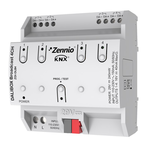
1. DALI channel output
5. Programming/Test button
Programming/test button: short button press to set programming mode. If this button is held while plugging the device into the KNX bus, it goes into
safe mode.
Programming/Test LED: programming mode indicator (red). When the device goes into safe mode, it blinks (red) every half second. The test mode is
indicated by the green color. During start up (after reset or power failure) and if the device is not in safe mode, LEDs indicator blinks red once.
GENERAL SYSTEM SPECIFICATIONS
CONCEPT
Type of device
Voltage (typical)
Voltage range
KNX supply
Maximum
consumption
Bus connection
Voltage and frequency
Ext. power
supply
Maximum consumption
Ambient temperature
Storage temperature
Ambient humidity
Storage humidity (relative)
Complementary characteristics
Safety class
Operation type
Device action type
Electrical solicitations period
Type of protection
Assembly
Minimal clearances
KNX bus failure response
Response when restarting KNX bus
Operation indication
Weight
PCB CTI index
Enclosure
(1)
Maximum consumption in the worst case scenario (KNX Fan-In model)
© Zennio Avance y Tecnología S.L.
2. External supply
6. External supply LED
DESCRIPTION
Electric operation control device
29VDC SELV
21...31VDC
Voltage
29VDC (typical)
(1)
24VDC
Typical bus connector TP1; 0,80mm² section
110/230VAC 50/60Hz
150mA
from 0ºC to +45ºC
from -20ºC to +55ºC
5 to 95% RH (no condensation)
5 to 95% RH (no condensation)
Class B
II
Continuous operation
Type 1
Long
IP20, clean environment
Independent control assembly device to be mounted inside of electrical panels with
DIN rail (EN 50022).
Not required
Data saving according to parameterization.
Data recovering change according to parameterization.
Programming LED indicates programming mode (red) and test mode (green). Each
DALI channel LED indicates its status (flashing = error, see Fig. 2; fixed = active
output). Power supply LED indicates the presence of supply voltage.
124g
175V
PC FR V0 halogen free
Edition 1
DALIBOX Broadcast 4CH
1
5
6
2
Figure 1. DALIBOX Broadcast 4CH
3. DALI channel control button
7. Programming/Test LED
mA
7
10
Further information
www.zennio.com
Technical Documentation
1
4
3
7
8
4. DALI channel status LED
8. KNX connector
mW
203
240
Page. 1 / 2
Advertisement
Table of Contents

Related Manuals for Zennio KNX-DALI


Summary of Contents for Zennio KNX-DALI
- Page 1 DALIBOX Broadcast 4CH KNX-DALI Broadcast Interface for up to 4 channels Technical Documentation ZDI-DLB4 FEATURES Control of up to 20 DALI ballasts per channel in up to 4 channels. Ballast replacement allowed with automatic detection. Error detection and monitoring (except multiaddress DALI ballasts).
- Page 2 The device has a short-circuit protection fuse that, in case of activation, it should not be rearmed or replaced except for our technical department. The WEEE logo means that this device contains electronic parts and it must be discarded properly following the instructions of http://zennio.com/weee-regulation. Page. 2 / 2 © Zennio Avance y Tecnología S.L. Edition 1 Further information www.zennio.com...
Need help?
Do you have a question about the KNX-DALI and is the answer not in the manual?
Questions and answers