Advertisement
Quick Links
KNX-DALI Interface for up to 64 ballasts per channel - 2 channels
ZDID64X2
FEATURES
•
Interface for two DALI channels
•
Possibility of controlling up to 64 DALI ballasts per channel
•
Single Master DALI-2 Controller
•
Compatibility with emergency lighting and color ballasts (DT8)
•
Supports KNX Data Secure
•
Scene sending and saving
•
Error detection and monitoring
•
Burn-in, Stand-by and Auto-off functions
•
Manual control through buttons and status indication through display
•
1.54" display (128 x 64 pixels) for settings and notifications
•
External power supply of 110-240 VAC 50/60 Hz
•
Total data saving on KNX bus failure
•
Integrated KNX BCU (TP1-256)
•
Size 67 x 90 x 79 mm (4.5 DIN units)
•
DIN rail mounting according to IEC 60715 TH35, with fixing clamp
•
DALI Standard certified
•
Conformity with the CE, UKCA, RCM directives (marks on the right side)
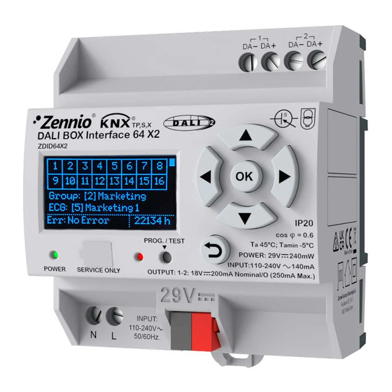
1. DALI bus channel
5. Programming LED
Programming button: short press to set programming mode. If this button is held while plugging the device into the KNX bus, it enters the safe mode. In
order to perform a KNX Secure factory reset, while the device is in safe mode, press the button for 10 seconds until the programming LED changes its
state.
Programming/Test LED: programming mode indicator (red). When the device enters the safe mode, it blinks (red) every half second. e is not in safe
mode, it starts a blue blinking sequence.
GENERAL SPECIFICATIONS
CONCEPT
Type of device
Voltage (typical)
Voltage range
Connection type
KNX supply
Maximum
consumption
External power
Voltage
supply
Maximum consumption
Operation temperature
Storage temperature
Operation humidity
Storage humidity
Complementary characteristics
Protection class / Overvoltage category
Operation type
Device action type
Electrical stress period
Degree of protection
Installation
Minimum clearances
Response on KNX bus failure
Response on KNX bus restart
Operation indicator
Weight
PCB CTI index
Housing material
¹ Maximum consumption in the worst-case scenario (KNX Fan-In model).
© Zennio Avance y Tecnología S.L.
2. Control buttons
6. Power supply indicator LED
DESCRIPTION
Electric operation control device
29 VDC SELV
21-31 VDC
Typical TP1 bus connector for 0.8 mm Ø rigid cable
Voltage
29 VDC (typical)
24 VDC¹
110-240 VAC 50/60 Hz PF=0.5
140 mA @ 110 VAC / 85 mA @ 230 VAC
-5 .. +45 °C
-20 .. +55 °C
5 .. 95%
5 .. 95%
Class B
II / III (4200 V)
Continuous operation
Type 1
Long
IP20, clean environment
Independent device to be mounted inside electrical panels with DIN rail (IEC
60715)
Not required
Data saving according to parameterization
Data recovery according to parameterization
The programming LED indicates programming mode (red). The power
supply LED indicates external power (green). Display allows both
configuring the DALI system and supervising the current status.
252 g
175 V
PC FR V0 halogen free
Edition 1
DALI BOX Interface 64 X2
3
4
5
6
7
Figure 1: DALI BOX Interface 64 X2
3. Display
7. External power supply
mA
6,2
10
Further information
www.zennio.com
TECHNICAL DOCUMENTATION
2
1
8
4. Programming button
8. KNX connector
mW
179.8
240
Page 1/2
Advertisement

Related Manuals for Zennio DALI BOX Interface 64 X2


Summary of Contents for Zennio DALI BOX Interface 64 X2
- Page 1 DIN rail mounting according to IEC 60715 TH35, with fixing clamp • DALI Standard certified • Conformity with the CE, UKCA, RCM directives (marks on the right side) Figure 1: DALI BOX Interface 64 X2 1. DALI bus channel 2. Control buttons 3. Display 4. Programming button 5.
- Page 2 • The facility must be equipped with a device that ensures the omnipolar sectioning. Installation of a 10 A mini-circuit-breaker is recommended. To prevent accidents, it must remain open in case of manipulation of the device. • The device has a short-circuit protection fuse that, in case of activation, should only be rearmed or replaced by the Zennio technical service.
Need help?
Do you have a question about the DALI BOX Interface 64 X2 and is the answer not in the manual?
Questions and answers