Advertisement
Quick Links
KNX-DALI Interface for flush mounting for up to 16 ballasts and 16 groups
ZDIIBD16
FEATURES
•
Possibility of controlling up to 16 DALI ballasts and up to 16 lighting
groups
•
Single Master DALI-2 Controller
•
Compatibility with emergency lighting and color ballasts (DT8)
•
Supports KNX Data Secure
•
Configuration and commisioning thorugh ETS App
•
Scene sending and saving
•
Error detection and monitoring
•
Burn-in, Stand-by and Auto-off functions
•
Manual control through button
•
Total data saving on KNX bus failure
•
Integrated KNX BCU (TP1-256)
•
Dimensions Ø 51.7 x 26.6 mm
•
Can be mounted within distribution boxes or wall back boxes
•
DALI-2 Standard certified
•
Conformity with the CE, UKCA, RCM directives (marks on the back
side)
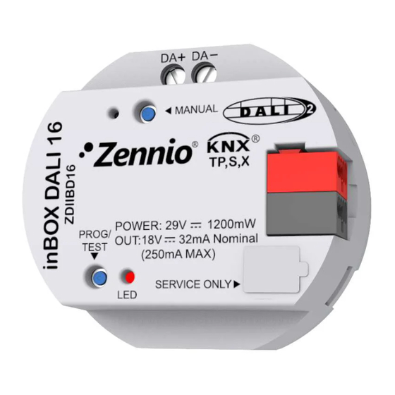
1. DALI bus channel
4. Programming LED
Programming button: short press to set programming mode. If this button is held while plugging the device into the KNX bus, it enters the safe mode. In
order to perform a KNX Secure factory reset, while the device is in safe mode, press the button for 10 seconds until the programming LED changes its
state.
Programming LED: programming mode indicator (red). When the device enters the safe mode, it blinks (red) every half second.
GENERAL SPECIFICATIONS
CONCEPT
Type of device
Voltage (typical)
Voltage range
Connection type
KNX supply
Maximum
consumption
External power
Voltage
supply
Maximum consumption
Operation temperature
Storage temperature
Operation humidity
Storage humidity
Complementary characteristics
Protection class / Overvoltage category
Operation type
Device action type
Electrical stress period
Degree of protection
Installation
Minimum clearances
Response on KNX bus failure
Response on KNX bus restart
Operation indicator
Weight
PCB CTI index
Housing material
¹ Maximum consumption in the worst-case scenario (KNX Fan-In model).
© Zennio Avance y Tecnología S.L.
2. Output control button
5. Programming button
DESCRIPTION
Electric operation control device
29 VDC SELV
21-31 VDC
Typical TP1 bus connector for 0.8 mm Ø rigid cable
Voltage
29 VDC (typical)
24 VDC¹
Not required
0
0 .. +55 °C
-20 .. +55 °C
5 .. 95%
5 .. 95%
Class B
II / III (800 V)
Continuous operation
Type 1
Long
IP20, clean environment
Independent device to be mounted inside distribution boxes or wall back
boxes
Not required
Data saving according to parameterization
Data recovery according to parameterization
The programming LED indicates programming mode (red). The output LED
indicates its status
60 g
175 V
PC FR V0 halogen free
Edition 1
2
3
4
5
mA
39.8
50
Further information
www.zennio.com
inBOX DALI 16
TECHNICAL DOCUMENTATION
1
Figure 1: inBOX DALI 16
3. Output status LED
6. KNX connector
mW
1154.2
1200
Page 1/2
6
Advertisement

Related Manuals for Zennio inBOX DALI 16


Summary of Contents for Zennio inBOX DALI 16
- Page 1 • DALI-2 Standard certified • Conformity with the CE, UKCA, RCM directives (marks on the back side) Figure 1: inBOX DALI 16 1. DALI bus channel 2. Output control button 3. Output status LED 4. Programming LED 5. Programming button 6.
- Page 2 • The WEEE logo means that this device contains electronic parts and it must be properly disposed of by following the instructi ons at https://www.zennio.com/en/legal/weee-regulation. • This device contains software subject to specific licences. For details, please refer to https://zennio.com/licenses. © Zennio Avance y Tecnología S.L.
Need help?
Do you have a question about the inBOX DALI 16 and is the answer not in the manual?
Questions and answers