
Related Manuals for Zennio DALIBOX Interface 64/32


Summary of Contents for Zennio DALIBOX Interface 64/32
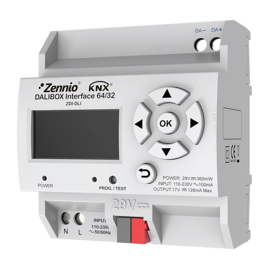
- Page 1 DALIBOX Interface 64/32 KNX-DALI Interface for 64 devices / 32 groups ZDI-DLI Application Program Version: [1.5] Manual Edition: [1.5]_a www.zennio.com...
-
Page 2: Table Of Contents
DALIBOX Interface 64/32 CONTENTS DALIBOX Interface 64/32 ....................5 Installation ........................7 Compatible Ballasts ....................... 9 General Configuration ....................13 2.1.1 Error Objects ....................... 18 2.1.2 Standby Mode ..................... 22 Enabling Ballasts ......................25 Enabling Groups ......................27 No Group ........................28 2.4.1... - Page 3 DALIBOX Interface 64/32 2.8.3 ECG Detection ..................... 63 2.8.4 Switch All ECGs ....................64 2.8.5 Reset All ECGs ..................... 64 2.8.6 Manual Control ....................65 2.8.7 Scene Control ...................... 66 2.8.8 Burn-in Control ....................66 2.8.9 Application Version ..................... 67 http://www.zennio.com...
- Page 4 DALIBOX Interface 64/32 DOCUMENT UPDATES Version Changes Page(s) Changes in the application program: • New ECG automatic detection functionality. [1.5]_a 13, 63 • New collisions Detections functionality. Changes in the application program: • Self-contained Battery Light (Converter) ECG functionality added.
-
Page 5: Dalibox Interface 64/32
1 INTRODUCTION 1.1 DALIBOX INTERFACE 64/32 DALIBOX Interface 64/32 from Zennio is a KNX-DALI gateway that allows controlling, dimming and monitoring up to 64 ballasts (in up to 32 groups) in a DALI bus by means of KNX communication objects, which makes it possible to integrate the DALI installation into the building automation system. - Page 6 DALIBOX Interface 64/32 Support for the Burn-in mode, required by certain lamps during the switch-on in order to ensure an optimal life period. Test mode and manual configuration of the DALI installation through the on-board display and pushbuttons. Heartbeat or periodical “still-alive” notification.
-
Page 7: Installation
DALIBOX Interface 64/32 1.2 INSTALLATION DALIBOX Interface 64/32 connects to the KNX bus through the on-board KNX connector. Once the device is provided with power from the KNX bus, both the individual address and the associated application program can be downloaded. - Page 8 To get detailed information about the technical features of the device, as well as on the installation and security procedures, please refer to the corresponding Datasheet, bundled with the original package of the device and also available at www.zennio.com. http://www.zennio.com Technical Support: http://support.zennio.com...
-
Page 9: Compatible Ballasts
DALIBOX Interface 64/32 1.3 COMPATIBLE BALLASTS DALIBOX Interface 64/32 is able to control DALI-certified ballasts (i.e., with the DALI logo) that make use of only one individual address. Specifically, it is designed to be compatible with types 0, 1, 2, 3, 4, 5, 6 and 7 of the DALI device type classification, shown in Table 1. - Page 10 DALIBOX Interface 64/32 circumstance – the ballast will maintain the last dimming value that may have been set. Some lamps may implement a significant delay when they are switched on. Such circumstance must be taken into account in case of parameterising timed actions or flashing and dimming sequences.
- Page 11 DALIBOX Interface 64/32 2 CONFIGURATION The DALIBOX Interface 64/32 application program allows controlling up to 64 DALI ballasts divided into up to 32 groups. Such control is performed according to a set of customisable options which make DALIBOX Interface 64/32 a very versatile device: Different alternatives to control the luminosity of the connected loads: ➢...
- Page 12 DALIBOX Interface 64/32 Sequences: up to 16 different sequences, which can be associated to different groups. Up to five step actions per sequence can be defined, as well as the dimming type of each step action among other things. Lock: group control enabling/disabling, with the additional option to define actions for the lock and unlock events.
-
Page 13: General Configuration
DALIBOX Interface 64/32 2.1 GENERAL CONFIGURATION The general configuration of DALIBOX Interface 64/32 basically consists in defining the dimming times. They are the length of the transition from switched off (0%) to the maximum luminosity level (100%), which determines the speed of the regulation. Up to... - Page 14 DALIBOX Interface 64/32 If ECG Automatic Detection is not enabled, DALIBOX Interface 64/32 will only be able to monitor ballast whose individual address have been detected before for the device. Collisions Detections: this functionality analyses the responses of the ballasts to detect those that have been assigned the same individual address.
- Page 15 DALIBOX Interface 64/32 Figure 2. General Dimming Times: three dimming times may be parameterised, through the following parameters: ➢ Dimming Time n [1…5…255] [s/min] : sets dimming time n (1-3). ➢ Dimming Time Objects [enabled/disabled]: enables three general two-byte objects, named “Dimming Time n”, which allow changing the dimming times parameterised.
- Page 16 DALIBOX Interface 64/32 ➢ Heartbeat (Periodical Alive Notification) [enabled/disabled]: this parameter lets the integrator incorporate a one-bit object to the project (“[Heartbeat] Object to Send ‘1’”) that will be sent periodically with a value of “1” to notify that the device is still working (still alive).
- Page 17 DALIBOX Interface 64/32 • Object Polarity [0 = Unlock; 1= Lock / 0 = Lock; 1 = Unlock]: defines whether the manual control lock/unlock should take place respectively upon the reception (through the aforementioned object) of values “0” and “1”, or the opposite.
-
Page 18: Error Objects
DALIBOX Interface 64/32 2.1.1 ERROR OBJECTS DALIBOX Interface 64/32 is able to detect certain errors that may occur during normal operation, which will be indicated through the display (section 2.8) or reported to the KNX bus (periodically every minute), if configured. - Page 19 64/32 will report an ECG presence error for each ballast. The diagnostic errors are errors detected by the ballasts themselves. DALIBOX Interface 64/32 is informed about them when it requests the status from the ballast. ➢ ECG Failure: the ballast cannot operate normally. The reasons that cause this error depend on the manufacturer.
- Page 20 DALIBOX Interface 64/32 Note that in case the ballast does not implement this function, DALIBOX Interface 64/32 will not be able to report these errors (see section 1.3). Blocking errors (short-circuit and lack of power supply) will interrupt all actions, including timed actions.
- Page 21 Regardless of the selected type, the object will be automatically sent as soon as DALIBOX Interface 64/32 is notified about the occurrence of any of these errors in any of the ballasts. The error type and ballast address are coded in the object value, according to the specification of the DPTs.
-
Page 22: Standby Mode
2.1.2 STANDBY MODE When enabled, DALIBOX Interface 64/32 sends a one-bit object to the KNX bus thirty seconds after every group is switched off. This allows making use of an external actuator to interrupt the power supply of the ballasts, thus reducing the power consumption. - Page 23 DALIBOX Interface 64/32 It is important to note that this functionality may have certain consequences over ballast replacements or group error detections. For example: While the Standby mode remains active (i.e., while the ballast power supply remains interrupted), DALI-related errors such as the ballast presence error or the diagnostic errors will no longer be detected.
- Page 24 DALIBOX Interface 64/32 Figure 9. Standby Object Polarity [0 = Standby Off; 1 = Standby On / 0 = Standby On; 1 = Standby Off]: sets value will be sent through “Standby (Status)” on the activation and the deactivation of the Standby mode.
-
Page 25: Enabling Ballasts
DALIBOX Interface 64/32 can control up to 64 ballasts, distributed along up to 32 groups. Bear in mind that ballasts can still be configured even if they are not assigned any group (which can be manually done afterwards, by means of the display). - Page 26 DALIBOX Interface 64/32 downloading the new parameterisation or maintained in case it had already been performed (either through previous parameter downloads or by means of the on-board controls and display). In case this option is left disabled, the following parameter is shown: ➢...
-
Page 27: Enabling Groups
DALIBOX Interface 64/32 2.3 ENABLING GROUPS Any group containing at least one ballast (or that may contain it after later assignments performed via the display of the device) must be explicitly enabled. Moreover, this makes it possible to configure the desired functions for each group, as described in section 2.5. -
Page 28: No Group
Operating time counter: function that informs the KNX bus about the operation time, i.e., how much time the ballast has remained under a dimming level greater than 0% since DALIBOX Interface 64/32 took over the control of the ballast. ECG Type: sets the ECG type. - Page 29 Enable Operating Time Counter Object [enabled/disabled]: enables the “[ECG N] Operating Time” four-byte object, which shows (in seconds, although updated every hour) how much time DALIBOX Interface 64/32 has been regulating the ballast with a dimming level greater than 0%. This object can be overwritten to change the value, for example in case of a ballast replacement.
- Page 30 DALIBOX Interface 64/32 2.4.1.1 EMERGENCY TESTS When “Converter” is selected as ECG Type, the following objects turn visible: [ECG N] Converter Test Control: Controls a test of a DALI converter. Furthermore, it allows to stop running test and to reset test flags. These object follows the following coding: 0: Reserved.
- Page 31 DALIBOX Interface 64/32 HS: Hardware Status. Indicates hardware status: 0: Hardwired Inhibit is activated. 1: Hardwired switch is on: digital input that the converter can have to switch its light on or off when normal mode is activated. 2 - 3: Reserved.
- Page 32 DALIBOX Interface 64/32 LDTR: Last Duration Test Result. Contains the battery discharge time as the result of the last successful duration test indicated in minutes. LPDTR: Last Partial Duration Test Result. Provides the remaining battery charge level after the last partial duration test.
-
Page 33: Group N
Dimming value during DALI bus failure: sets the dimming level that will be adopted by the ballasts of the channel if communication errors take place between DALIBOX Interface 64/32 and the ballasts, which may be due to short-circuits or to a power supply failure. - Page 34 DALIBOX Interface 64/32 ETS PARAMETERISATION As new groups are enabled (see section 2.3), additional sub-tabs will be incorporated with name “Group N”, being N their specific numbers. These tabs, on their side, contain a set of new sub-tabs. The first one, “Configuration”, provides the following parameters: Name: desired identifier for the group (up to twelve characters).
-
Page 35: Ecg M
2.5.3 LIMITS DALIBOX Interface 64/32 allows configuring two different limit types: Luminosity Limits: they limit the luminosity ranges controlled by the ballast. These limits are not perceptible by the user, i.e., the dimming range for the KNX bus will still be 0-100%, and the dimming time between both ends (0% to 100%) will be exactly the dimming time parameterised. - Page 36 DALIBOX Interface 64/32 ➢ Ballast Physical Minimum: minimum luminosity value that the ballast is actually able to produce, as specified by the manufacturer. This determines the actual luminosity level that will correspond to a dimming percentage of Note: physical minimum must be configured as indicated in the ballast or in the datasheet.
-
Page 37: Switch & Dimming
➢ Maximum Dimming Value [0…100] [%]. 2.5.4 SWITCH & DIMMING DALIBOX Interface 64/32 lets configuring the general On/Off switch control so that these actions are performed immediately or through a smooth regulation (according to one of the three configurable dimming times detailed in section 2.1). - Page 38 DALIBOX Interface 64/32 parameterised. If not enabled, the group will remain at the minimum level parameterised. Absolute dimming: modifies the dimming level through orders that specify the desired target value, regardless of the current value of the group. A one-byte object is provided for the reception of the absolute dimming orders.
- Page 39 DALIBOX Interface 64/32 Switch On/Off (1 bit): ➢ Switch-On Value [Last On Value / Defined Value]: allows selecting the general dimming level that will be adopted by the group when the value “1” is received through “[Group n] On/Off”. The dimming level will be applied when sending a switch on value, with the group switched on or off.
-
Page 40: Status Objects
DALIBOX Interface 64/32 2.5.5 STATUS OBJECTS DALIBOX Interface 64/32 provides different objects that report the current dimming state of the output group: A one-bit object (On/Off). A one-byte object, which indicates the dimming level (in percentage). ETS PARAMETERISATION After enabling this function, the following options will be available in the “Status Objects”... -
Page 41: Custom On/Off
DALIBOX Interface 64/32 2.5.6 CUSTOM ON/OFF This function offers one additional On/Off control for each group, and therefore another new communication object to switch the ballasts on and off. This additional control can be customised with specific dimming levels for the “On” and “Off”... -
Page 42: Timers
DALIBOX Interface 64/32 2.5.7 TIMERS This function allows configuring a simple timer and a flashing sequence in the output group, being it possible to enable or disable both functions independently. The simple timer function consists in a switch-on of the group (with an optional... - Page 43 DALIBOX Interface 64/32 2.5.7.1 SIMPLE TIMER The simple timer function requires configuring the following options: On Duration: time the group must remain on before being automatically switched off (unless the stop order is received from the bus, which will switch the group off immediately).
- Page 44 DALIBOX Interface 64/32 Figure 20. Simple Timer On Duration [0…255] [s/min]: sets the time the group will remain on. The value “0” will disable the automatic switch-off, thus making the group remain on. On Delay [0…255] [s/min]: sets a delay after the reception of value “1” through object “[Group n] Simple Timer”.
- Page 45 DALIBOX Interface 64/32 Example: On duration: 4 s. On delay: 2 s. Off delay: 2 s. On value: 100%. Dimming time: immediate. Assuming that the “1” labels correspond to the arrivals of the value “1” through the “[Group n] Simple Timer” and that the “0” labels correspond to the arrival of the value “0”, the expected behaviour will be:...
- Page 46 DALIBOX Interface 64/32 2.5.7.2 FLASHING The flashing function requires configuring the following options: On Duration: length of each “On” stage during the sequence. Off Duration: length of each “Off” stage during the sequence. Repetitions: number of iterations of the sequence.
-
Page 47: Lock
DALIBOX Interface 64/32 On Value [1…100] [%]: sets a specific dimming percentage to be applied to the group during the “On” stages. Final Value [0…100] [%]: sets a specific dimming value to be applied to the group after the last repetition or after the reception of one “0” through the “[Group n] Flashing”... -
Page 48: Custom Initialisation
DALIBOX Interface 64/32 options are analogous to those for locking, but will also comprise the following one: “Previous State” (to recover the status previous to the lock order). 2.5.9 CUSTOM INITIALISATION This function lets customising the state of the group after the start-up of the device. -
Page 49: Modes
➢ Delay [0…255] [s]: sets a delay before performing this sending. 2.5.10 MODES DALIBOX Interface 64/32 implements two special operation options named as Burn-in mode and Auto-Off mode, each of which is explained in detail next. 2.5.10.1 AUTO OFF MODE The Auto Off mode allows an automatic switch-off of the group if it is found to be steady (i.e., without receiving further dimming orders) under a certain dimming value –or... - Page 50 DALIBOX Interface 64/32 ETS PARAMETERISATION Once the Modes option has been enabled, the following parameters regarding the Auto Off function will show in ETS: Figure 24. Modes Auto Off [enabled/disabled]: allows enabling the Auto Off function. ➢ Threshold Value [1…10…100] [%]: dimming value beneath which the Auto Off will be triggered in case the group remains steady at that value for more than the threshold time.
- Page 51 DALIBOX Interface 64/32 regulation to 100%, or to 0% in other case): Relative and absolute dimming. Simple timers and flashing. Lock/unlock actions. Initialisation. Installation test (see section 2.8). DALI bus failure (see section 2.5.1). An object is provided to force the activation or deactivation of the Burn-in mode at any time.
- Page 52 DALIBOX Interface 64/32 The following parameters will also be available: ➢ Burn-in Time [1…100…255] [h]: sets the time the Burn-in mode should last. ➢ Start Burn-in After Programming [enabled/disabled]: sets whether the start-up actions configured (see section 2.5.9) should be applied the Burn- in restrictions or not.
-
Page 53: Scenes
This feature allows defining different scenes (i.e., specific ambiances or dimming sequences), which can be activated by sending the corresponding trigger values to a one-byte object. DALIBOX Interface 64/32 offers up to 32 configurable scenes which can be assigned to the different enabled groups. ETS PARAMETERISATION Once this function has been enabled, the following object will show in ETS: “Scene Control”... -
Page 54: Scene N
DALIBOX Interface 64/32 Each scene activated from this screen will have a specific tab associated, labelled as “Scene ‘n’”, as detailed next. 2.6.2 SCENE N Each of up to 32 scenes must be assigned a certain identifier, i.e., their scene number with regards to the KNX system. -
Page 55: Sequences
DALIBOX Interface 64/32 2.7 SEQUENCES 2.7.1 CONFIGURATION This feature allows defining up to 16 configurable dimming sequences, which can perform actions on different groups. Sequences can be executed simultaneously, as starting a new one does not stop other sequences in execution. -
Page 56: Sequence N
DALIBOX Interface 64/32 Figure 28. Configuration 2.7.2 SEQUENCE N Each sequence can consist of up to five actions executed sequentially. For each of the actions, it is possible to set the group over which the action will be performed, as well as the target dimming value, the dimming type (at once or smooth) and the total length of the action prior to trigger the next one. - Page 57 DALIBOX Interface 64/32 Next Sequence [No Sequence / Sequence n]: in case the sequence is not cyclic, this parameter allows the execution of another sequence after the last action of the current one. Each sequence allows enabling up to five actions: Figure 30.
- Page 58 DALIBOX Interface 64/32 Dimming Time [At Once / Dimming Time 1 / Dimming Time 2 / Dimming Time 3 / Time to Next Action]. In case of selecting “Time to Next Action”, the dimming time –i.e., the total time for a transition from 0% to 100– will match the action time, which is configured through the next parameter.
-
Page 59: Display
DALIBOX Interface 64/32 2.8 DISPLAY 2.8.1 MAIN MENU DALIBOX Interface 64/32 incorporates a 128x64 pixel display together with six additional buttons to browse through the options it shows. During normal device operation of the device, the screen remains off to save power. - Page 60 DALIBOX Interface 64/32 Checking any errors on the ECGs and resetting the presence error. Checking the operating hours of the ECGs and resetting the time count. All the above actions can be performed over any ECGs present in the line, even if they have not been enabled in parameters before (see section 2.2).
- Page 61 After entering this section, ◄ and ► will permit browsing through the available addresses (both unused addresses and addresses already in use). Free addresses and addresses automatically assigned by DALIBOX Interface 64/32 (which therefore have not been given a name in ETS; see section 2.2) will simply show as a number in square brackets, with no name.
- Page 62 When assigning an address that was already assigned to another ballast, DALIBOX Interface 64/32 will automatically assign the latter a new address. In case the sixty-four addresses are already in use, the assignment will not be possible: after pressing on OK, the current address will remain assigned. In...
-
Page 63: Ecg Detection
This box shows the total operation hours of the selected ballast (see section 2.4.1 and section 2.5.2) even if the associated object has not been enabled in parameters. Note that this count is performed by DALIBOX Interface 64/32 according to the hours it maintains the ballast dimming level over 0%. -
Page 64: Switch All Ecgs
2.8.5 RESET ALL ECGS This submenu allows resetting all the ballasts connected to the bus to their defaults, thus removing their address assignments, after which DALIBOX Interface 64/32 will proceed with the automatic ECG detection and address assignment process after one minute. -
Page 65: Manual Control
DALIBOX Interface 64/32 Note: as Reset is an action manage for the user, ECG Detection will be enabled the first detection cycle in order to monitor the reset ballasts. After the first loop, ECG Detection status will return to the previous. -
Page 66: Scene Control
DALIBOX Interface 64/32 2.8.7 SCENE CONTROL This submenu allows manually controlling the scene execution and saving. Scene saving will only be possible in case it has been enabled in parameters (section 2.6). After entering this submenu, a table with the 16 available scenes is shown. Please make use of ◄, ►, ▼... -
Page 67: Application Version
DALIBOX Interface 64/32 Important: in case the burn-in mode of a particular group has not been enabled in parameters, it will still show up in the group selection table, however the message “Burn- in state: not available” will be shown if trying to activate it. - Page 68 DALIBOX Interface 64/32 ANNEX I. COMMUNICATION OBJECTS “Functional range” shows the values that, with independence of any other values permitted by the bus according to the object size, may be of any use or have a particular meaning because of the specifications or restrictions from both the KNX standard or the application programme itself.
- Page 69 DALIBOX Interface 64/32 305, 316, 327, 338, 349, 0xF (Inc. by 1%) 20, 31, 42, 53, 64, 75, 86, 97, 108, 119, 130, 141, 152, 163, 174, 185, 196, 207, 218, 229, 240, 1 Byte C - W - -...
- Page 70 DALIBOX Interface 64/32 202, 213, 224, 235, 246, 257, 268, 279, 290, 301, 312, 323, 334, 345, 356, 27, 38, 49, 60, 71, 82, 93, 104, 115, 126, 137, 148, 159, 170, 181, 192, 0 = Stop Burn-in ; 1 = Start Burn-...
- Page 71 Join and send us your inquiries about Zennio devices: http://support.zennio.com Zennio Avance y Tecnología S.L. C/ Río Jarama, 132. Nave P-8.11 45007 Toledo (Spain). Tel. +34 925 232 002 www.zennio.com info@zennio.com...
Need help?
Do you have a question about the DALIBOX Interface 64/32 and is the answer not in the manual?
Questions and answers