
Related Manuals for Farm King 12112


Summary of Contents for Farm King 12112
- Page 1 OPERATOR AND PARTS MANUAL Backsaver Auger Model 12112 and 12122 012015 SZ102632 © 062013 | Rev 1 | 88664296...
-
Page 3: Table Of Contents
Table of Contents - Backsaver Auger 12112 / 12122 TABLE OF CONTENTS Manufacturer’s Statement: For technical reasons, Buhler Industries Inc. reserves the right to modify machinery design and specifications provided herein without any preliminary notice. Information provided herein is of descriptive nature. -
Page 4: Table Of Contents - Backsaver Auger
Table of Contents - Backsaver Auger 12112 / 12122... -
Page 5: Safety
Customer / Owner’s Signature: Remove this Warranty Registration Form from the Operator And Parts Manual. Make two copies of the form. Send original Warranty Registration Form to Farm King. Give one copy to the customer and the dealer will keep one copy. - Page 6 Warranty Registration - Backsaver Auger 12112 / 12122...
-
Page 7: Introduction
Farm King equipment. READ AND UNDERSTAND THIS OPERATOR AND PARTS MANUAL BEFORE OPERATING YOUR FARM KING EQUIPMENT. If you have any questions, see your Farm King dealer. This manual may illustrate options and accessories not installed on your Farm King equipment. - Page 8 Introduction - Backsaver Auger 12112 / 12122...
-
Page 9: Owner's Information
Introduction - Backsaver Auger 12112 / 12122 Serial Number Location OWNER’S INFORMATION Thank you for your decision to purchase a Farm King Please enter the model and serial number in the space 12112 / 12122 Backsaver Auger. To ensure maximum provided for easy reference. -
Page 10: Assembly
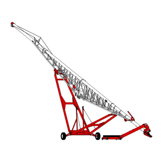
Introduction - Backsaver Auger 12112 / 12122 EQUIPMENT IDENTIFICATION Component Location DISCHARGE SPOUT BRIDGING SUPPORT AND CABLES TOP TRUSS TUBING WELDMENT HOPPER HEAD ASSEMBLY LOWER TRUSS TUBING WELDMENT LOWER TUBING LIFT WELDMENT DISCHARGE TUBING STOP WELDMENT HOPPER LIFT ASSEMBLY TRACK CAR... - Page 11 Safety - Backsaver Auger 12112 / 12122 SAFETY SAFETY INSTRUCTIONS ............13 Safe Operation Is The Operator’s Responsibility .
-
Page 12: Safety - Backsaver Auger
Safety - Backsaver Auger 12112 / 12122... -
Page 13: Safety Instructions
Safety - Backsaver Auger 12112 / 12122 SAFETY INSTRUCTIONS Safe Operation Needs A Qualified Operator Safe Operation Is The Operator’s Responsibility Safety Alert Symbol Operators must have instructions before operating the machine. Untrained operators can cause injury This symbol with a warning statement means: or death. -
Page 14: Use Safety Rules
Safety - Backsaver Auger 12112 / 12122 SAFETY INSTRUCTIONS (CONT’D) Transport Safety Use Safety Rules • Do not exceed 20 mph (32 kph). Reduce speed on • Read and follow instructions in this manual and the rough roads and surfaces. -
Page 15: Safety Rules For Power Take-Off (Pto) Driven Equipment
Safety - Backsaver Auger 12112 / 12122 Safety Rules For Power Take-Off (PTO) Driven Machine Requirements And Capabilities Equipment • Stop the machine and engage the parking brake. • Keep PTO shields and all guards in place. Replace Install blocks in front of and behind the rear tires of the damaged or missing shields and guards before machine. -
Page 16: Fire Prevention
Operation The Farm King machine must be in good operating condition before use. Check all of the items listed on the service schedule under the 8 hour column. (See “SERVICE SCHEDULE” on page 104.) -
Page 17: Welding And Grinding
Safety - Backsaver Auger 12112 / 12122 FIRE PREVENTION (CONT’D) Welding And Grinding Always clean the machine and equipment, disconnect the battery, and disconnect the wiring from the machine controls before welding. Cover rubber hoses, battery and all other flammable parts. Keep a fire extinguisher near the machine when welding. -
Page 18: Operation
Safety - Backsaver Auger 12112 / 12122 OPERATING SAFETY ZONE Safety Zone Identification ELECTROCUTION HAZARD • Owners operators Keep away from power lines, AVOID INJURY OR DEATH should allow only electrocution occur authorized personnel and • allow small without direct contact. -
Page 19: Safety Signs (Decals)
Follow the instructions on all the Signs (Decals) that are on the equipment. Replace any damaged signs (decals) and be sure they are in the correct locations. Equipment signs are available from your Farm King equipment dealer. Intake Elbow / Drive Section (Right Side) - Page 20 Safety - Backsaver Auger 12112 / 12122 SAFETY SIGNS (DECALS) (CONT’D) Intake Elbow / Drive Section (Left Side) B-3114 p/n SZ06136 p/n SZ06135...
- Page 21 Safety - Backsaver Auger 12112 / 12122 SAFETY SIGNS (DECALS) (CONT’D) Auger Hitch Intake Auger B-3021 B-3104 p/n SZ06023 p/n SZ06527...
- Page 22 Safety - Backsaver Auger 12112 / 12122 SAFETY SIGNS (DECALS) (CONT’D) Intake Auger B-3116 p/n SZ06011 p/n SZ06136...
- Page 23 Safety - Backsaver Auger 12112 / 12122 SAFETY SIGNS (DECALS) (CONT’D) Drop Spout Upper / Lower Trusses B-3093 B-1132 p/n SZ06023 p/n SZ06136 p/n SZ06023...
- Page 24 Safety - Backsaver Auger 12112 / 12122 SAFETY SIGNS (DECALS) (CONT’D) Lower Truss / Winch Upper Undercarriage Arms B-3081 B-3051 WARNING AN OPERATOR’S MANUAL IS FURNISHED WITH EACH GRAIN AUGER. ADDITIONAL OR REPLACEMENT MANUALS ARE AVAILABLE. DO NOT OPERATE THE UNIT BEFORE READING AND UNDERSTANDING THE OPERATOR’S MANUAL.
- Page 25 Safety - Backsaver Auger 12112 / 12122 SAFETY SIGNS (DECALS) (CONT’D) Lower Tube WARNING AN OPERATOR’S MANUAL IS FURNISHED WITH EACH GRAIN AUGER. ADDITIONAL OR REPLACEMENT MANUALS ARE AVAILABLE. DO NOT OPERATE THE UNIT BEFORE READING AND UNDERSTANDING THE OPERATOR’S MANUAL.
-
Page 26: Equipment Decals And Signs
Safety - Backsaver Auger 12112 / 12122 EQUIPMENT DECALS AND SIGNS Part Number SZ06052 NOTE: All safety related decals are shown in the Safety Signs Section. (See “SAFETY SIGNS (DECALS)” on page 19.) Check and replace any worn, torn, hard to read or missing decals on your equipment. - Page 27 Safety - Backsaver Auger 12112 / 12122 EQUIPMENT DECALS AND SIGNS (CONT’D) Part Number SZ06094 Part Number SZ06101 Part Number SZ06001 Part Number 108143 Black Feterl...
-
Page 28: Safety Sign-Off Form
Untrained operators and failure to follow instructions can cause injury or death. Farm King follows the general Safety Standards specified by the American Society of Agricultural and Biological Engineers (ASABE) and the Occupational Safety and Health Administration (OSHA). Anyone who will be operating and / or maintaining the Backsaver Auger must read and clearly understand ALL Safety, Operating and Maintenance information presented in this manual. - Page 29 Assembly - Backsaver Auger 12112 / 12122 ASSEMBLY GENERAL ASSEMBLY INFORMATION ..........31 Component Unloading And Identification .
- Page 30 Assembly - Backsaver Auger 12112 / 12122...
-
Page 31: General Assembly Information
NOTE: If any components are damaged, missing or replacement parts are required, contact your Component Unloading And Identification Farm King Dealer. Assemble the 12112 / 12122 Backsaver Auger in the following order: 1. Undercarriage (See “Undercarriage Assembly” on page 32.) -
Page 32: Base Group
Assembly - Backsaver Auger 12112 / 12122 BASE GROUP Figure 4 Undercarriage Assembly Assemble the undercarriage on flat level surface. B-3001 Install straps (Item 1) around the axle weldment (Item 2) [Figure 4]. • DO NOT permit bystanders to be in the work area Connect the strap to an approved lifting device. - Page 33 Assembly - Backsaver Auger 12112 / 12122 Figure 6 Figure 8 B-3004 B-1018 Install straps (Item 1) around the axle weldment (Item 2) Install the tire / wheel (Item 1) with the valve stem facing [Figure 8]. Connect straps to an approved lifting device.
- Page 34 Assembly - Backsaver Auger 12112 / 12122 Figure 9 Figure 11 B-1104 B-3049 Install straps (Item 1) around the track car (Item 2) Install a strap (Item 1) around the rear undercarriage [Figure 11]. weldment (Item 2) [Figure 9]. Connect the strap to an approved lifting device.
- Page 35 Assembly - Backsaver Auger 12112 / 12122 Figure 13 B-1105 Align the track car with the back end (away from the axle) of the rear undercarriage weldment as shown [Figure 13]. Install the 1-1/4” x 40-1/4” pin (Item 1) [Figure 13]...
-
Page 36: Tube Assembly
Assembly - Backsaver Auger 12112 / 12122 BASE GROUP (CONT’D) Figure 15 Tube Assembly Assemble the tube on a flat level surface. B-3006 • DO NOT permit bystanders to be in the work area Install a strap (Item 1) through the bracing of the lower when unloading and assembling the auger truss tube weldment (Item 2) [Figure 15]. - Page 37 Assembly - Backsaver Auger 12112 / 12122 Figure 17 Figure 19 B-3008 B-3005 Install a strap (Item 1) around the lower tube weldment (Item 2) [Figure 19]. Align the lower truss tube weldment hinge pin mounts (Item 1) with the hinge pin mounts (Item 2) [Figure 17] Connect the strap to an approved lifting device.
- Page 38 Assembly - Backsaver Auger 12112 / 12122 Figure 21 Figure 22 B-3009 B-3121 Slide the lower tube weldment (Item 1) against the lower truss tube weldment (Item 2) [Figure 22]. Align the holes Align the flighting shaft connecting holes (Item 1) [Figure in the two flanges and install twelve 1/2”...
- Page 39 Assembly - Backsaver Auger 12112 / 12122 Figure 24 Figure 26 B-3011 B-3013 Raise the lower truss tube weldment and align the Locate two 1/2” x 6-1/2” threaded rods (Item 1). Thread mounting holes of the lower tube weldment (Item 1) and two 1/2”...
- Page 40 Assembly - Backsaver Auger 12112 / 12122 Adjusting Lower Tube Weldment To The Right Adjusting Lower Tube Weldment To The Left Figure 28 Figure 29 INTAKE END INTAKE END B-3015 B-3015A If the lower tube weldment is offset to the right, verify that...
- Page 41 Assembly - Backsaver Auger 12112 / 12122 Figure 30 When tightening the half clamp bolts and nuts, verify the lower tube remains level as each 2-bolt half clamp is tightened, and verify the lower tube remains level until the last 2-bolt half clamp on the lower tube has been tightened.
- Page 42 Assembly - Backsaver Auger 12112 / 12122 Figure 33 Figure 35 B-3054 B-3122 Position the top truss tube weldment against the lower Move the top truss tube weldment (Item 1) towards the truss tube weldment. Using a punch, align the holes in lower truss tube weldment (Item 2) [Figure 33] and align the lower and top truss tube weldments.
- Page 43 Assembly - Backsaver Auger 12112 / 12122 Figure 37 Figure 39 B-1112 B-1143 Install a strap around the discharge tube weldment. Align the flighting shaft connecting holes (Item 1) [Figure 39] and slide the flighting sections together. Connect the strap to an approved lifting device.
- Page 44 Assembly - Backsaver Auger 12112 / 12122 Figure 40 Figure 42 EQUAL SPACE B-1037 B-1115 Align and install one 2-bolt half clamp (Item 1) [Figure Slide the discharge tube weldment (Item 1) against the 42] over the discharge tube weldment (all locations).
- Page 45 Assembly - Backsaver Auger 12112 / 12122 Raise the lower truss tube weldment (intake end) to lower Figure 46 the discharge tube weldment to the desired assembly height. Figure 44 B-3013A Locate two 1/2” x 6-1/2” threaded rods (Item 1). Thread two 1/2”...
- Page 46 Assembly - Backsaver Auger 12112 / 12122 Adjusting Discharge Tube Weldment To The Left Adjusting Discharge Tube Weldment To The Right Figure 48 Figure 49 DISCHARGE END DISCHARGE END B-3061B B-3061 If the discharge tube weldment is offset to the left, verify...
- Page 47 Assembly - Backsaver Auger 12112 / 12122 Figure 50 Figure 52 B-3019 B-3127 Install straps (Item 1) through the drive section (Item 2) Align the flighting shaft connecting holes (Item 1) [Figure [Figure 50] as shown. 52] and slide the flighting sections together.
- Page 48 Assembly - Backsaver Auger 12112 / 12122 Figure 53 B-3019 Move the drive section (Item 1) towards the lower tube (Item 2) [Figure 53]. Align and install 1/2” - 1-1/2” bolts (Item 3) [Figure 53] through the drive section and lower tube flange (from the inside of the drive section) open holes.
- Page 49 Assembly - Backsaver Auger 12112 / 12122 Figure 54 Figure 56 B-3090 B-1178 Install the bearing flange (Item 1) onto the four 5/8” studs. Apply an anti-seize lubricant to the lower drive shaft (Item Install four 5/8” lock nuts (Item 2) [Figure 56] on the 1) [Figure 54].
- Page 50 Assembly - Backsaver Auger 12112 / 12122 Figure 58 Figure 60 1/4” - 3/8” maximum gap B-3093 B-1185 Install the bearing shield (Item 1), then install one 3/8” Check the gap between the flighting and bearing mount. lock nut (Item 2) [Figure 60] onto each 3/8” stud and tighten.
- Page 51 Assembly - Backsaver Auger 12112 / 12122 Figure 62 Figure 64 B-3020 B-3030 Install the hopper winch plate (Item 1) using two 1/2” x 1” Install the PTO hanger (Item 1) onto the drive section bolts (Item 2) [Figure 62] and 1/2” lock nuts.
- Page 52 Assembly - Backsaver Auger 12112 / 12122 Figure 66 Figure 68 B-3033 B-3036 Install the 5/16” x 1-3/4” key (Item 1) [Figure 66] onto the Using a punch (Item 1) [Figure 68], align the two gearbox shaft (PTO drive). mounting holes.
- Page 53 Assembly - Backsaver Auger 12112 / 12122 Figure 70 Figure 72 B-3038 B-3124 Rotate the PTO driveline 90°. Rotate the PTO driveline up. Install the rubber strap (Item 1) around the PTO driveline and hook to the PTO hanger Using a hex wrench (Item 1) [Figure 70], tighten the set (Item 2) [Figure 72].
-
Page 54: Installing The Track Car
Assembly - Backsaver Auger 12112 / 12122 Installing The Track Car Figure 75 Figure 73 B-1127 B-3068 Place one track car guide (Item 1) on the frame of top truss tube weldment (Item 2) just forward of the last first Install straps (Item 1) around one of the upper vertical support (Item 3) [Figure 75] (discharge end). -
Page 55: Installing The Axle Risers
Assembly - Backsaver Auger 12112 / 12122 Installing The Axle Risers Installing The STOP LIFT Sign Figure 76 Figure 78 B-1129 B-1137 Install a strap (Item 1) through the axle riser (Item 2) Position the STOP LIFT sign (Item 1) [Figure 78] and [Figure 76] as shown. -
Page 56: Track Car / Winch Cable Routing
Assembly - Backsaver Auger 12112 / 12122 Track Car / Winch Cable Routing Figure 80 LEFT AXLE RISER B-1224 TRACK WINCH RIGHT AXLE RISER B-1173 Thread the cable under the sheave (Item 1) [Figure 80] on the left side of the lower truss, up over the top sheave on the left axle riser, then to the bottom of the sheave on the upper truss and route towards the track car. -
Page 57: Winch Assembly And Installation
Assembly - Backsaver Auger 12112 / 12122 Winch Assembly And Installation Figure 83 Figure 81 B-1074 Align the hydraulic motor (Item 1) [Figure 83] as shown B-1067 and install onto the gasket. Remove the two 1/2” x 2” bolts (Item 1) and cover (Item 2) [Figure 81] from the winch assembly. - Page 58 Assembly - Backsaver Auger 12112 / 12122 Figure 85 Figure 87 B-3027 B-4079 Install the second sheave weldment (Item 1) onto the hopper lift. Install one 1/2” flat washer and one 1/8” hair Install the hopper lift (Item 1) onto the mounting plate on pin (Item 2) [Figure 87] to secure the sheave to the the lower tube.
- Page 59 Assembly - Backsaver Auger 12112 / 12122 Figure 90 CUT HAZARD To prevent injury to fingers and hands: B-0582 • Always wear heavy leather gloves when handling a wire rope. Install the cable clamp (Item 1) [Figure 90] using the two •...
-
Page 60: Hopper Assembly And Installation
Assembly - Backsaver Auger 12112 / 12122 Hopper Assembly And Installation Figure 94 Figure 92 B-3125 Install two straps (Item 1) around the hopper (Item 2) B-3078 [Figure 94]. Align the flex extension (rubber flap) (Item 1) holes with Connect the straps to an approved lifting device. - Page 61 Assembly - Backsaver Auger 12112 / 12122 Figure 95 Figure 97 B-3086 Install the CV joint (Item 1) on the drive shaft (center) of the hopper. Install a 3/8” x 3” bolt (Item 2) through the CV B-1228 joint and drive shaft. Install a 3/8” lock nut (Item 3) [Figure 97] on the bolt and tighten the nut against the CV Locate four axle pins (Item 1) [Figure 95].
- Page 62 Assembly - Backsaver Auger 12112 / 12122 Figure 99 Figure 101 B-3088 B-3100 Install a strap (Item 1) onto the hopper head (Item 2) Align the hopper drive tube flighting (Item 1) with the CV [Figure 101]. joint (Item 2) [Figure 99], move hopper drive tube towards hopper until the flighting fully engages the CV Connect the straps to an approved lifting device.
- Page 63 Assembly - Backsaver Auger 12112 / 12122 Figure 103 Figure 105 B-3102 B-3104 Move the hopper head towards the hopper drive tube Install the hopper access door (Item 1) onto the hopper. until the flighting shaft fully engages the u-joint.
- Page 64 Assembly - Backsaver Auger 12112 / 12122 Figure 107 Figure 109 B-1212 B-3107 Install four retaining washers (Item 1) onto the four studs Install two straps (Item 1) [Figure 107] around the and over the hopper head flange. Install four 1/2” lock hopper drive tube.
-
Page 65: Hydraulic Assembly
Assembly - Backsaver Auger 12112 / 12122 HYDRAULIC ASSEMBLY Figure 112 Winch Fitting And Hose Installation When installing and servicing hydraulic systems, clean the work area before assembly or disassembly and keep all parts clean. Always use caps and plugs on hoses, hydraulic tubes and ports to keep dirt out. -
Page 66: Winch Cable Installation
Assembly - Backsaver Auger 12112 / 12122 WINCH CABLE INSTALLATION Connect the winch hydraulic hoses to the tractor. (See “Connecting Disconnecting Hydraulic Lines” Cable Routing and Installation page 82.) Enter the tractor and start the engine. (See “Entering And Figure 115 Leaving The Operator’s Position”... - Page 67 Assembly - Backsaver Auger 12112 / 12122 Figure 119 Spooling the cable onto the winch drum will require three people. • One person to operate the tractor controls. • One person to guide the cable. • One person to direct the tractor operator.
-
Page 68: Top Tube Support Cable Installation (12122 Model Only)
Assembly - Backsaver Auger 12112 / 12122 Top Tube Support Cable Installation (12122 Model Only) Figure 122 Keep hands a minimum of 3 feet from the winch while spooling cable. Figure 121 B-3094 Install one eyebolt anchor bar (Item 1) on the first vertical support (from discharge end) on the upper truss with cross bracing (Item 2) [Figure 122] (both sides). - Page 69 Assembly - Backsaver Auger 12112 / 12122 Figure 123 Figure 125 B-3095 B-3096 Route the cables over the upper tension cable truss (Item Feed the 3/8” cable through the eyebolt (Item 1) and 1) and install a cable clamp (Item 2) [Figure 125] on the around the thimble (both sides).
- Page 70 Assembly - Backsaver Auger 12112 / 12122 Figure 127 B-3097 Feed the 3/8” cable through the bracket (Item 1) [Figure 127], around the thimble (both sides). Pull the cable as tight as possible by hand. Install two cable clamps (Item 2) [Figure 127] on the cable (both sides).
- Page 71 Operation - Backsaver Auger 12112 / 12122 OPERATION GENERAL INFORMATION ............73 Pre - Operation Checklist .
- Page 72 Operation - Backsaver Auger 12112 / 12122...
-
Page 73: General Information
Operation - Backsaver Auger 12112 / 12122 GENERAL INFORMATION 4. Check wheel bolts for tightness. Torque as required. (See “Wheel Bolt Torque” on page 110.) Pre - Operation Checklist 5. Check the augers. Remove any material build-up or Before operating the Backsaver Auger for the first time debris that has become entangled. -
Page 74: Break - In Checklist
Operation - Backsaver Auger 12112 / 12122 Break - In Checklist 1. Check the auger hitch for damaged, loose or missing parts. Repair as needed before operation. NOTE: The Backsaver Auger must have a break-in period with different operating conditions 2. -
Page 75: Tractor Requirements
Operation - Backsaver Auger 12112 / 12122 Tractor Requirements Drawbar Adjustment Figure 130 14 in. (357 mm) • Do NOT exceed 540 RPM PTO. • Keep PTO shields and all guards in place. • Keep away from moving parts. •... -
Page 76: Entering And Leaving The Operator's Position
Operation - Backsaver Auger 12112 / 12122 Entering And Leaving The Operator’s Position INITIAL SET-UP Connecting The Backsaver Auger To The Tractor Always inspect the tractor’s drawbar and Backsaver Auger hitch before connecting. See the tractor’s owner’s manual. Verify that the tractor’s drawbar is adjusted correctly for... -
Page 77: Connecting The Pto Driveline
Operation - Backsaver Auger 12112 / 12122 Figure 132 Figure 133 B-0111 B-3021 Install the hitch pin (Item 1) [Figure 133] and retaining pin to securely fasten the Backsaver Auger hitch to the Turn the handle (Item 1) [Figure 132] clockwise to raise tractor drawbar. -
Page 78: Disconnecting The Pto Driveline
Operation - Backsaver Auger 12112 / 12122 Stop the engine and leave the operator’s position. (See Disconnecting The PTO Driveline “Leaving The Operator’s Position” on page 76.) Park the tractor / equipment on a flat level surface. Stop the engine and leave the operator’s position. (See “Leaving The Operator’s Position”... -
Page 79: Pto Driveline
Operation - Backsaver Auger 12112 / 12122 PTO Driveline PTO Driveline Bottoming Out Check PTO Driveline Length Check Stop the engine and leave the operator’s position. (See “Leaving The Operator’s Position” on page 76.) NOTE: Due to variations in distances between tractor... - Page 80 Operation - Backsaver Auger 12112 / 12122 Reducing The PTO Driveline Length Figure 136 Stop the engine and leave the operator’s position. (See Auger PTO “Leaving The Operator’s Position” on page 76.) Shaft Make sure the PTO driveline and all rotating components have come to a complete stop before leaving the operator’s position.
- Page 81 (from Step 3), the PTO driveline does not Shaft B-0218 have adequate engagement and should be replaced with a longer driveline. See your Farm King dealer for available PTO drivelines. 2. Measure the retracted (compressed) length of the PTO driveline between the bases of the plastic guards...
-
Page 82: Connecting / Disconnecting Hydraulic Lines
Operation - Backsaver Auger 12112 / 12122 Connecting / Disconnecting Hydraulic Lines To Connect: Figure 140 HIGH PRESSURE FLUID HAZARD To prevent serious injury or death from high pressure fluid: • Relieve pressure on system before repairing or B-0531 adjusting. -
Page 83: Axle Extension Installation
Operation - Backsaver Auger 12112 / 12122 Axle Extension Installation Figure 142 CRUSHING HAZARD • Park the equipment on a solid level surface before raising any part of the equipment. B-1018 • Always support the load after raised. • Do not work under a load supported by a jack or Remove the wheel bolts (Item 1) and remove the tire blocked parts. - Page 84 Operation - Backsaver Auger 12112 / 12122 Figure 144 Figure 146 B-1013 B-1018 Align the axle extension (Item 1) with the axle mounting Align and install the tire (Item 1). Install the eight wheel plate. Install five 5/8” x 2” bolts (Item 2) [Figure 144] bolts (Item 2) [Figure 146].
-
Page 85: Lowering And Raising The Hopper
Operation - Backsaver Auger 12112 / 12122 Lowering And Raising The Hopper • Frayed, kinked or damaged wire rope must be replaced immediately. • Always stand clear of wire rope and hopper during operation. • Always stand clear and keep others away during operation. - Page 86 Operation - Backsaver Auger 12112 / 12122 Figure 148 B-1083 Remove the hopper lift cable hook (Item 1) [Figure 148] from the hopper.
-
Page 87: Hydraulic Hopper Mover Operation
Operation - Backsaver Auger 12112 / 12122 Hydraulic Hopper Mover Operation Figure 149 Never operate the hydraulic hopper mover or hydraulic hopper lift when the PTO is engaged. B-1096 The hopper powered wheels are not designed to push grain, rocks, dirt etc. when in use. Always keep... -
Page 88: Raising The Auger
Operation - Backsaver Auger 12112 / 12122 Raising The Auger • Do not operate the unit before reading and ELECTROCUTION HAZARD understanding the Operator’s Manual. • Keep all safety devices in place. prevent serious injury death from electrocution: • Keep off the equipment at all times. - Page 89 Operation - Backsaver Auger 12112 / 12122 With the axle extensions installed and main auger in the fully down position, move the auger towards the bin or barn. Position the auger as close as possible to the bin or barn with the tractor as close to in-line with the auger as possible.
-
Page 90: Auger Placement
Operation - Backsaver Auger 12112 / 12122 Auger Placement ELECTROCUTION HAZARD prevent serious injury death from electrocution: • Be aware of overhead power lines. • Keep away from power lines when transporting or raising auger. • Electrocution can occur without direct contact. - Page 91 Operation - Backsaver Auger 12112 / 12122 Disconnect The IID (PTO) from the tractor. Failure to Do not place blocks under the wheels to increase follow this step EVERY time BEFORE maneuvering the elevation of auger. OR changing the auger elevation may cause damage to the tractor and / or auger IID.
-
Page 92: Lowering The Auger
Operation - Backsaver Auger 12112 / 12122 Lowering The Auger • Do not operate the unit before reading and ELECTROCUTION HAZARD understanding the Operator’s Manual. prevent serious injury death from • Keep all safety devices in place. electrocution: • Keep off the equipment at all times. -
Page 93: Loading Grain Into The Hopper
Operation - Backsaver Auger 12112 / 12122 LOADING GRAIN INTO THE HOPPER Figure 155 Unloading Belly Dump Units Figure 153 B-0538 Move the belly dump unit forward until the rear B-0534 compartment is directly over the hopper (Item 1) [Figure 155]. - Page 94 Operation - Backsaver Auger 12112 / 12122 Figure 156 B-0539 Move the belly dump unit back until the front compartment is directly over the hopper (Item 1) [Figure 156]. • Do NOT exceed 540 RPM PTO. • Keep PTO shields and all guards in place.
-
Page 95: Unloading Rear And Side Dump Units
Operation - Backsaver Auger 12112 / 12122 Unloading Rear And Side Dump Units Rear Dump Units Figure 157 • Do NOT exceed 540 RPM PTO. • Keep PTO shields and all guards in place. • Keep away from moving parts. - Page 96 Operation - Backsaver Auger 12112 / 12122 Side Dump Units Figure 158 • Do NOT exceed 540 RPM PTO. • Keep PTO shields and all guards in place. • Keep away from moving parts. • Keep bystanders away. With tractor running at a low idle, engage the tractor PTO B-0542 slowly to start the auger.
-
Page 97: Transporting
Operation - Backsaver Auger 12112 / 12122 TRANSPORTING Requirements Never exceed 20 mph (32 kph). ELECTROCUTION HAZARD prevent serious injury death from electrocution: • Be aware of overhead power lines. • Keep away from power lines when transporting or raising auger. -
Page 98: Transporting Procedure
Operation - Backsaver Auger 12112 / 12122 Transporting Procedure Figure 160 Remove all supports on the discharge end and anchoring from the intake end (if required). Disconnect the PTO driveline from the tractor. (See “Connecting The PTO Driveline” on page 77.) Lower the auger. - Page 99 Operation - Backsaver Auger 12112 / 12122 Figure 163 CRUSHING HAZARD • Park the equipment on a solid level surface before raising any part of the equipment. • Always support the load after raised. B-1018 • Do not work under a load supported by a jack or blocked parts.
- Page 100 Operation - Backsaver Auger 12112 / 12122 Figure 165 Figure 167 B-1013 B-1018 Remove the five 5/8” x 2” bolts (Item 1) [Figure 165] Align and install the tire (Item 1). Install the eight wheel (three bolts on the bottom / two on top).
-
Page 101: Maintenance
Maintenance - Backsaver Auger 12112 / 12122 MAINTENANCE TROUBLESHOOTING ............103 Chart . - Page 102 Maintenance - Backsaver Auger 12112 / 12122...
-
Page 103: Troubleshooting
Maintenance - Backsaver Auger 12112 / 12122 TROUBLESHOOTING Chart Instructions are necessary before operating or servicing equipment. Read and understand the Operator And Parts Manual and safety signs (decals) on equipment. Follow warnings and instructions in the manuals when making repairs, adjustments or servicing. Check for correct function after adjustments, repairs or service. -
Page 104: Service Schedule
Maintenance - Backsaver Auger 12112 / 12122 SERVICE SCHEDULE Maintenance Intervals Maintenance work must be done at regular intervals. Failure to do so will result in excessive wear and early failures. The service schedule is a guide for correct maintenance of the Backsaver Auger. -
Page 105: Lubrication
Maintenance - Backsaver Auger 12112 / 12122 LUBRICATION Locations Recommendations Always use a good quality multi-purpose / lithium base grease when lubricating the equipment. Fluid such as engine oil, hydraulic fluid, coolants, grease, etc. must disposed environmentally safe manner. Some regulations require that certain spills and leaks on the ground must be cleaned in a specific manner. - Page 106 Maintenance - Backsaver Auger 12112 / 12122 NOTE: The auger PTO driveline is equipped with Figure 172 extended life bearings. Do not over-grease. Figure 170 B-3093 Apply two - three pumps of grease to the drop spout hanger bearing (Item 1) [Figure 172].
- Page 107 Maintenance - Backsaver Auger 12112 / 12122 Figure 174 Figure 176 B-1198 B-1218 Apply two - three pumps of grease to the hopper flight u- joints (Item 1) [Figure 174]. Apply two - three pumps of grease to the horizontal sheaves (Item 1) [Figure 176].
- Page 108 Maintenance - Backsaver Auger 12112 / 12122 Figure 178 Figure 180 B-1086 B-1184 Check the winch gearbox oil level every 50 hours or Apply two - three pumps of grease to the sheaves (Item weekly. 1) [Figure 178] on the track car.
-
Page 109: 668 Upper Gearbox
Maintenance - Backsaver Auger 12112 / 12122 668 Upper Gearbox 968 Lower Gearbox Figure 181 Figure 182 668 GEARBOX 968 GEARBOX Check the gearbox oil level every 50 hours or weekly. Check the gearbox oil level every 50 hours or weekly. -
Page 110: Axle
Maintenance - Backsaver Auger 12112 / 12122 AXLE Figure 183 Wheel Bolt Torque Check the torque on wheel bolts daily. Tighten bolts to 110 - 125 lb. / ft. (149 - 169 N•m) torque. Tire / Wheel Replacement Empty the Backsaver Auger (if required). -
Page 111: Main Auger Shear Bolt
Maintenance - Backsaver Auger 12112 / 12122 MAIN AUGER SHEAR BOLT Figure 184 Replacement NOTE: 12” Backsaver Augers use a 5/16” x 3” grade 5 shear bolt, located on the top shaft of the lower gearbox and lower internal power shaft u-joint. -
Page 112: Safety Sign (Decal) Installation
Maintenance - Backsaver Auger 12112 / 12122 SAFETY SIGN (DECAL) INSTALLATION Procedure When replacing safety signs (decals), temperature must be above 10° C (50° F). • Remove all portions of the damaged safety sign (decal). • Thoroughly clean the area with glass cleaner. -
Page 113: Storage And Return To Service
After the Farm King Backsaver Auger has been in storage, it is necessary to follow a list of items to return Sometimes it may be necessary to store your Farm King the equipment to service. Backsaver Auger for an extended period of time. Below is a list of items to perform before storage. - Page 114 Maintenance - Backsaver Auger 12112 / 12122...
-
Page 115: Parts Identification
Parts Identification - Backsaver Auger 12112 / 12122 PARTS IDENTIFICATION GENERAL INFORMATION ............117 HYDRAULIC PARTS . - Page 116 Parts Identification - Backsaver Auger 12112 / 12122...
-
Page 117: General Information
Parts Identification - Backsaver Auger 12112 / 12122 GENERAL INFORMATION The parts identification section list descriptions, part numbers and quantities for 12112 & 12122 Backsaver Augers. Contact your Farm King dealer for additional 12112 & 12122 Backsaver Augers parts information. -
Page 118: Lower Gearbox Sz0160112
Parts Identification - Backsaver Auger 12112 / 12122 LOWER GEARBOX SZ0160112 24, 25 11, 12... - Page 119 Parts Identification - Backsaver Auger 12112 / 12122 ITEM PART NUMBER DESCRIPTION SZ126046 5/16-18UNC x 3/4” HHCS, G5 SZPG-4110 COVER SZPG-1503 SHIM, 0.010 SZPG-1502 SHIM, 0.0075 SZPG-1501 SHIM, 0.005 CASE, 68 DEGREE SZPG-1537 SHIM, 0.007 x 1.25 I.D. SZPG-1853 VENT, 1/8 NPT, 5 PSI SZPG-1650 KEY, 1/4 SQ x 7/8”...
-
Page 120: Upper Gearbox Sz0160100
Parts Identification - Backsaver Auger 12112 / 12122 UPPER GEARBOX SZ0160100 11, 14 5, 6 5, 6 10, 11, 14 5, 6 11, 14 4, 12... - Page 121 Parts Identification - Backsaver Auger 12112 / 12122 ITEM PART NUMBER DESCRIPTION CASE, 68 DEGREE SZPG-1192 QUILL SZPG-1193 COVER, OPEN SZPG-1246 GEAR, 19T, 1-1/4” SZ100125 BEARING CONE, (LM67048) SZ100126 BEARING CUP, (LM67010) SZPG-1471 SEAL, 1.25 - 2.00 SZ8742128904 SEAL, 1.25 - 2.375...
-
Page 122: Undercarriage
Parts Identification - Backsaver Auger 12112 / 12122 UNDERCARRIAGE ITEM PART NUMBER DESCRIPTION SZ102601 AXLE, WELDMENT, 12-112 & 122 SZ102602 UNDERCARRIAGE, WELDMENT, REAR, 12-112 & 122 SZ0211248 TRACK CAR ASSEMBLY, 12-122 SZ0211302 AXLE EXTENSION WELDMENT, 12-122 SZ02113001 SPINDLE & HUB ASSEMBLY, 12-122... -
Page 123: Track Car Guide Assembly
Parts Identification - Backsaver Auger 12112 / 12122 TRACK CAR GUIDE ASSEMBLY ITEM PART NUMBER DESCRIPTION SZ0211249 GUIDE, TRACK CAR, 12112 / 12122 SZ990211248008 3/8” DIA x 13/16” NYLON BUSHING SZ128016 COTTER PIN, 1/8” x 1” AXLE EXTENSIONS ITEM PART NUMBER... -
Page 124: Spindle & Hub Assembly
Parts Identification - Backsaver Auger 12112 / 12122 SPINDLE & HUB ASSEMBLY ITEM PART NUMBER DESCRIPTION SZ0211300 WELDMENT, SPINDLE 12-122 SZDC13 DUST CAP, 6-BOLT HUB SZLM603049 INNER BEARING, LM603049 SZSE-1300 GREASE SEAL, P602115 SZWB11250 LUG BOLT, 9/16” x 1-1/8” SZ100125... -
Page 125: Axle Risers
Parts Identification - Backsaver Auger 12112 / 12122 AXLE RISERS ITEM PART NUMBER DESCRIPTION SZ102601 UNDERCARRIAGE AXLE, WELDMENT SZ107232 RISER, AXLE, LH, WELDMENT SZ107233 RISER, AXLE, RH., WELDMENT SZ126118 BOLT, HHCS, 5/8” - 11 UNC x 4-1/5” G5 SZ125036 LOCK NUT, 5/8” - 11 UNC... -
Page 126: Truss
Parts Identification - Backsaver Auger 12112 / 12122 TRUSS ITEM PART NUMBER DESCRIPTION SZ102482 WELDMENT, TUBING, 12”, TRUSS, TOP SECTION SZ102481 WELDMENT, TUBING, 12”, TRUSS, LOWER SECTION SZ126092 BOLT, HHCS, 1/2-13UNC 1-1/2” G5 SZ125032 LOCK NUT, 1/2” -13UNC NYLOCK SZ102634... -
Page 127: Bridging Cable And Support
Parts Identification - Backsaver Auger 12112 / 12122 BRIDGING CABLE AND SUPPORT (12122 MODELS ONLY) 11, 12 ITEM PART NUMBER DESCRIPTION ” 2 ” 8 - ” ” 8 ” 6 ” 2 SZ126089 BLT HHCS 1/2-13UNC 1" G5 SZ125032... -
Page 128: Discharge Spout
Parts Identification - Backsaver Auger 12112 / 12122 DISCHARGE SPOUT ITEM PART NUMBER DESCRIPTION SZ2011053 BEARING, 1-1/2” 4-BOLT CAST FI SZ2127212 ASSEMBLY, SHIELD, CAP, HEAD SZ6001050 NUT, 1-1/2” NC HEX W 3/8” SETSCREW SZ125032 LOCK NUT, 1/2” -13UNC NYLOCK SZ125030... -
Page 129: Main Tube Flighting
Parts Identification - Backsaver Auger 12112 / 12122 MAIN TUBE FLIGHTING ITEM PART NUMBER DESCRIPTION SZ102482 WELDMENT, TUBING, 12”, TRUSS, TOP SECTION SZ102481 WELDMENT, TUBING, 12”, TRUSS, LOWER SECTION SZ102479 WELDMENT, TUBING, LOWER, 12” AUGER, 360 SZ102480 WELDMENT, TUBING, 12” AUGER, CSW, DISCHARGE, 360 SZ126092 BOLT, HHCS, 1/2-13UNC 1-1/2”... -
Page 130: Lift Stop
Parts Identification - Backsaver Auger 12112 / 12122 LIFT STOP ITEM PART NUMBER DESCRIPTION SZ126076 BOLT, HHCS, 3/8” - 16UNC 3” G5 SZ3032424 PLATE, MOUNT, STRAP, 1.5” x 4.18” x 1/4” SZ125030 LOCK NUT, 3/8-16UNC NYLOCK SZ06086 DECAL, STOP LIFT, 8 x 8-3/4”... -
Page 131: Truss Lift Winch
Parts Identification - Backsaver Auger 12112 / 12122 TRUSS LIFT WINCH 5, 6, 7 ITEM PART NUMBER DESCRIPTION SZ9901233 HYDRAULIC WINCH MOUNT, 14” REAR SZ9901234 AUGER HYDRAULIC WINCH, 14” REAR PLATE SZ9901235 SIDE PLATE W/HOLE, 14” WINCH MOUNT SZ2121250 BRADEN HU 8A WINCH, 12-120 AUGER SZ126065 BOLT, HHCS, 3/8-16 UNC x 1”... -
Page 132: Drive Section
Parts Identification - Backsaver Auger 12112 / 12122 DRIVE SECTION 22, 23... - Page 133 Parts Identification - Backsaver Auger 12112 / 12122 ITEM PART NUMBER DESCRIPTION ” 8 ” 2 ” 1 ” 1 ” 6 ” 1 ” 6 - ” ” 3 - ” ” 3 ” 4 ” 8 ” 1 ”...
- Page 134 Parts Identification - Backsaver Auger 12112 / 12122 DRIVE SECTION CONTINUED 6, 7...
- Page 135 Parts Identification - Backsaver Auger 12112 / 12122 ITEM PART NUMBER DESCRIPTION SZ104492 12” DRIVE SECTION WELDMENT SZ104489 LOWER DRIVE SECTION CHANNEL COVER SZ0160112 GEAR BOX DRIVE SECTION - 2001 SZ125040 WING NUT, 5/16”-18 UNC SZ125041 WING NUT, 3/8”-16 UNC SZ126063 BOLT, HHCS 3/8”...
-
Page 136: Hopper Assembly
Parts Identification - Backsaver Auger 12112 / 12122 HOPPER ASSEMBLY 19, 12 19, 12 21, 14, 15 36, 37 1, 26, 29 6, 7 ITEM PART NUMBER DESCRIPTION SZ101817 WELDMENT, HOPPER BODY, 12” GROUND HUGGER SZ101820 WELDMENT, HOPPER, HANGER BEARING, 12” GROUND HUGGER SZ00405153 INTERNAL DRIVE, HOPPER SIDE SPROCKET, 12”... - Page 137 Parts Identification - Backsaver Auger 12112 / 12122 SZ0043534 ASSEMBLY, CHAIN ROLLER, #50 34P SZ0231110 BUSHING, MACH, 1” 10GA SZ0231140 BUSHING, MACH, 1” ID, 14GA SZ0237510 BUSHING, MACH, 3/4” SZ102638 PLATE, FORMED, MOUNT, BEARING HOPPER, 12 TOP SZ103292 PLATE, FORMED, MOUNT, BEARING HOPPER, 12 BOTTOM SZ125028 LOCK NUT, 1/4”...
-
Page 138: Hopper Drive Tube
Parts Identification - Backsaver Auger 12112 / 12122 HOPPER DRIVE TUBE... - Page 139 Parts Identification - Backsaver Auger 12112 / 12122 ITEM PART NUMBER DESCRIPTION SZ9902531 HOPPER, HEAD ASSEMBLY SZ101824 WELDMENT, TUBING, DISCHARGE, 12” SZ9902393 WELDMENT, FLIGHT, 12” DISCHARGE SZ126076 BOLT HHCS, 3/8” - 16UNC 3” G5 SZ125030 LOCK NUT, 3/8-16UNC NYLOCK SZ01125118 KEY, SQ, 1/4”...
-
Page 140: Hopper Head Assembly
Parts Identification - Backsaver Auger 12112 / 12122 HOPPER HEAD ASSEMBLY... - Page 141 Parts Identification - Backsaver Auger 12112 / 12122 ITEM PART NUMBER DESCRIPTION SZ9901979 HOPPER HEAD SZ0160100 GEARBOX, HOPPER DRIVE, 2001 SZ1001604 12N U-JOINT, 1-1/4” x 1-1/4” SZ9902289 DRIVE SECTION ACCESS DOOR SZ126065 BOLT, HHCS, 3/8-16 UNC x 1” G5 SZ125040...
-
Page 142: Hopper Lift Assembly
Parts Identification - Backsaver Auger 12112 / 12122 HOPPER LIFT ASSEMBLY ITEM PART NUMBER DESCRIPTION SZ9901880 WELDMENT, ARM, SWING OVER SZ9902509 ASSEMBLY, CABLE, 3/16” 7 x 19 14” THIMBLE GRAB SZ02165035 WELDMENT, SHEAVE SZ127003 WASHER, FLAT, 1/2” SZ128018 PIN, HAIR, 1/8”... -
Page 143: Specifications
Specifications - Backsaver Auger 12112 / 12122 SPECIFICATIONS SPECIFICATIONS ............. 145 Dimensions . - Page 144 Specifications - Backsaver Auger 12112 / 12122...
-
Page 145: Specifications
Specifications - Backsaver Auger 12112 / 12122 SPECIFICATIONS Dimensions DESCRIPTION 12112 12122 Length 112’ 122’ Width 120” 120” Transport Height 16’ 3” 16’ 3” Maximum Discharge Height 65’ 7” 65’ 10” Performance DESCRIPTION 12112 12122 Size 12” x 112’ 12” x 112’... -
Page 146: Auger Height & Reach Chart
Specifications - Backsaver Auger 12112 / 12122 AUGER HEIGHT & REACH CHART MODEL 19° MAX. 19° MAX. 19° MAX. 19° MAX. 12112 112’ 38’ 1” 65’ 7” 43’ 2” 63’ 7” 23’ 6” 30’ 9” 33’ 41’ 7” 12122 122’... -
Page 147: Hardware Torque Values
Specifications - Backsaver Auger 12112 / 12122 HARDWARE TORQUE VALUES Metric Chart NOTE: Do not use the values listed in the charts if a different torque value or tightening procedure is specified in this manual for a specific application. Torque values listed are for general use only. -
Page 148: Imperial Chart
Specifications - Backsaver Auger 12112 / 12122 HARDWARE TORQUE VALUES (CONT’D) Imperial Chart NOTE: Do not use the values listed in the charts if a different torque value or tightening procedure is specified in this manual for a specific application. Torque values listed are for general use only. -
Page 149: Hydraulic Connection Specifications
Specifications - Backsaver Auger 12112 / 12122 HYDRAULIC CONNECTION SPECIFICATIONS Port Seal (O-ring Boss) Fitting O-Ring Fitting (Straight Thread) Figure 188 Lubricate the O-ring before installing the fitting. Loosen Port Seal And O-ring Boss Tightening Torque the jam nut and install the fitting. Tighten the jam nut until the washer is tight against the surface. - Page 150 Specifications - Backsaver Auger 12112 / 12122...
-
Page 151: Warranty
Warranty - Backsaver Auger 12112 / 12122 WARRANTY WARRANTY ..............153... - Page 152 Warranty - Backsaver Auger 12112 / 12122...
- Page 153 If Farm King determines that it will pay labor costs for warranty work, it will do so by issuing a credit to the dealer’s or distributor’s account.
- Page 154 Limited Warranty WARRANTY REQUIREMENTS To be covered by warranty, each new product must be registered with Farm King within thirty (30) days of delivery to original retail purchaser. If the customer decides to purchase replacement components before the warranty disposition of such components is determined, Farm King will bill the customer for such components and then credit the replacement invoice for those components later determined to be covered by this limited warranty.
-
Page 155: Alphabetical Index
Alphabetical Index - Backsaver Auger 12112 / 12122 ALPHABETICAL INDEX AUGER HEIGHT & REACH CHART ..146 STORAGE AND RETURN TO SERVICE . . 113 AXLE EXTENSIONS ....123 TRACK CAR GUIDE ASSEMBLY . - Page 156 Alphabetical Index - Backsaver Auger 12112 / 12122...
- Page 158 www.farm-king.com 411 Center Avenue West Salem, SD USA 57058-0398 Toll Free: 1-888-FK-80001 E-mail: info@buhler.com www.farm-king.com Equipment shown is subject to change without notice. ©2012 Buhler Trading Inc. Printed in Canada TSX:BUI...
Need help?
Do you have a question about the 12112 and is the answer not in the manual?
Questions and answers