
Subscribe to Our Youtube Channel
Related Manuals for Farm King VT3290


Summary of Contents for Farm King VT3290
- Page 1 OPERATOR AND PARTS MANUAL Vertical Tillage Model VT3290, VT3320, VT3345, VT3375 052017 88717097...
-
Page 3: Table Of Contents
Table Of Contents - VT3000 Series TABLE OF CONTENTS Manufacturer’s Statement: For technical reasons, Farm King reserves the right to modify machinery design and specifications provided herein without any preliminary notice. Information provided herein is of descriptive nature. Performance quality may depend on soil fertility, applied agricultural techniques, weather conditions, and other factors. - Page 4 Table Of Contents - VT3000 Series...
- Page 5 Customer / Owner Signature: Remove this Warranty Registration Form from the Operator And Parts Manual. Make two copies of the form. Send original Warranty Registration Form to Farm King. Give one copy to the customer and the dealer will keep one copy.
- Page 6 VT3000 Series...
-
Page 7: Introduction
Farm King equipment. READ AND UNDERSTAND THIS OPERATOR AND PARTS MANUAL BEFORE OPERATING YOUR FARM KING EQUIPMENT. If you have any questions, see your Farm King dealer. This manual may illustrate options and accessories not installed on your Farm King equipment. - Page 8 Introduction - VT3000 Series...
- Page 9 Model Number: work with it. Serial Number: Farm King is continually working to improve its products. Farm King reserves the right to make The serial number plate (Item 1) [Figure 1] is any improvements or changes as deemed practical located at the front of main frame.
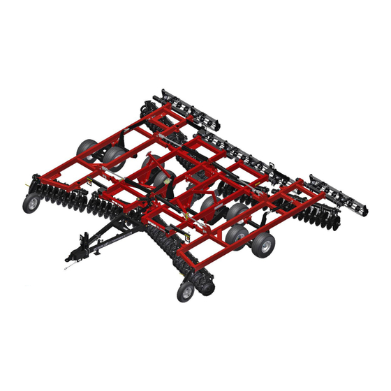
- Page 10 Introduction - VT3000 Series EQUIPMENT IDENTIFICATION Component Location SHOWN WITH ROLLER BASKET OPTION RH WING SCRAPER FRAME CENTER FRAME LIFT CYLINDER ROLLING BASKET GAUGE WHEEL LH WING FRAME BLADE MAIN ROCK JACK FRAME SHAFT LEVELING HITCH WING LINK WHEELS...
-
Page 11: Safety
Safety - VT3000 Series SAFETY SAFETY INSTRUCTIONS Safe Operation is The Operator’s Responsibility Safe Operation Needs A Qualified Operator Use Safety Rules Transport Safety Machine Requirements And Capabilities FIRE PREVENTION Maintenance Operation Starting Electrical Hydraulic System Fueling Welding And Grinding Fire Extinguishers SAFETY AND EQUIPMENT SIGNS (DECALS) SAFETY SIGN-OFF FORM... - Page 12 Safety - VT3000 Series...
-
Page 13: Safety Instructions
• The written instructions from Farm King include the minor or moderate injury. It may also be used to Warranty Registration, Dealer Inspection Report, alert against unsafe practices. -
Page 14: Use Safety Rules
Safety - VT3000 Series Use Safety Rules • DO NOT make any adjustments or repairs on the equipment while the machine is running. • Read and follow instructions in this manual and the • Keep shields and guards in place. Replace if damaged. tractor’s Operators Manual before operating. -
Page 15: Transport Safety
Safety - VT3000 Series Transport Safety Machine Requirements And Capabilities • Do not exceed 10 mph (16 kph). Reduce speed on • Fasten seat belt securely. If equipped with a foldable rough roads and surfaces. Roll-Over Protective Structure (ROPS), only fasten seat belt when ROPS is up and locked. -
Page 16: Fire Prevention
Operation • The Farm King machine must be in good operating condition before use. • Check all of the items listed on the service schedule • Stop the engine and let it cool before adding fuel. No under the 8 hour column (see “Maintenance”... -
Page 17: Welding And Grinding
Safety - VT3000 Series Welding And Grinding • Always clean the machine and equipment, disconnect the battery, and disconnect the wiring from the machine controls before welding. Cover rubber hoses, battery and all other flammable parts. Keep a fire extinguisher near the machine when welding. •... -
Page 18: Safety And Equipment Signs (Decals)
Safety - VT3000 Series SAFETY AND EQUIPMENT SIGNS (DECALS) Follow the instructions on all the signs (decals) that are on the equipment. Replace any damaged signs (decals) and be sure they are in the correct locations. Equipment signs are available from your Farm King equipment dealer. - Page 19 Safety - VT3000 Series 88719204 - FARMKING 4.50 X 27.75 (ITEM 8) Decal Identification [Figure 3] 86026768 - FLOURESCENT TAPE (ITEM 1) 88719272 - FARMKING 5.5 X 35.0 (ITEM 9) EZDF10060 - RED REFLECTOR 2 X 9 (ITEM 2) EZDF10061 - YELLOW REFLECTOR 2 X 9 (ITEM 3) 86058185 - HIGH PRESSURE FLUID (ITEM 11) EZDF13001 - WARNING HYDRUALIC (ITEM 4) 86054092 - OPERATOR’S MANUAL (ITEM 12)
- Page 20 Safety - VT3000 Series EZA75759 - IMPORTANT DECAL (ITEM 15) Decal information unavailable. 88719389 - VT3290 (ITEM 10) 88719390 - VT3320 (ITEM 10) 88719391 - VT3345 (ITEM 10) 88719392 - VT3375 (ITEM 10) 115793 - B.I.I. SERIAL# PLATE (ITEM 16)
-
Page 21: Safety Sign-Off Form
Untrained operators and failure to follow instructions can cause injury or death. Farm King follows the general Safety Standards specified by the American Society of Agricultural and Biological Engineers (ASABE) and the Occupational Safety and Health Administration (OSHA). Anyone who will be operating and / or maintaining the equipment must read and clearly understand ALL Safety, Operating and Maintenance information presented in this manual. - Page 22 Safety - VT3000 Series...
-
Page 23: Assembly
General Information Gang Beams Assembly GANG SECTION DIAGRAMS VT3290 Model - 28.5 Ft., 8 In Spacing VT3290 Model - 28.5 Ft., 9 In Spacing VT3320 Model - 32 Ft., 8 In Spacing VT3320 Model - 32 Ft., 9 In Spacing VT3345 Model - 34.5 Ft., 8 In Spacing... - Page 24 SCRAPER AND SCRAPER BAR Standard Scraper Assembly Heavy Duty Scraper Assembly HYDRAULIC HOSE BRACKET Manual Storage Container Assembly LIGHT KIT VT3290 & VT3320 Models VT3345 & VT3375 Models LIGHT KIT Routing DEPTH STOPS GAUGE WHEELS BASKET ROLLERS (OPTIONAL) Basket Roller Diagrams...
-
Page 25: General Assembly Information
GENERAL ASSEMBLY INFORMATION NOTE: If any components are damaged, missing or replacement parts are required, contact Component Unloading And Identification your Farm King Dealer. DANGER Assemble the VT3000 in the following order: Using the packing list, locate and place all components and hardware in one area. -
Page 26: Base Group
Assembly - VT3000 Series BASE GROUP NOTE: The following images throughout the assembly section of this manual may Main Frame Assembly not show the exact components as they Assemble the main frame on a flat level surface. appear but the procedure is correct for all VT3000 series units. - Page 27 Assembly - VT3000 Series Figure 8 NOTE: Support stands approximately 36 inches (914.4 mm) high equipped with rotating casters / wheels are recommended when assembling the main frame of the VT3000. Figure 6 Locate RH main frame section (Item 1). Install straps (Item 2) [Figure 8] around the RH main frame section.
- Page 28 Assembly - VT3000 Series Figure 10 Figure 12 FRONT Position the LH (Item 1) and RH (Item 2) [Figure Install four 1” x 3-1/2” bolts (Item 1) [Figure 12] 10] main frame sections over the main frame through the RH & LH main frames rear connecting rockshaft.
-
Page 29: Main Frame Rockshaft Assembly
Assembly - VT3000 Series Main Frame Rockshaft Assembly Figure 15 Figure 13 Twist rockshaft bearing (Item 1) and install around the main frame rockshaft (Item 2) [Figure 15]. Figure 16 Locate the rockshaft casting assemblies (Item 1) [Figure 13]. Remove nuts, lock washers and bolts (Item 2) [Figure 13]. - Page 30 Assembly - VT3000 Series Figure 17 Figure 19 Install straps (Item 1) [Figure 19] around the main rockshaft. Install one rockshaft bearing (Item 1) between the Connect the straps to an approved lifting device. two tabs (Item 2) next to the rockshaft cylinder arm (Item 3) [Figure 17].
- Page 31 The procedure is the same for the LH side of the main frame. Figure 21 VT3290 & VT3320 Models Tire Size: FS24 - 380 / 55R 16.5 Align wheel (Item 1) with the spindle. Install the eight 5/8” wheel nuts (Item 2) [Figure 23] (both wheels).
-
Page 32: Wing Support Bracket Assembly
Assembly - VT3000 Series Wing Support Bracket Assembly Install four 1/2” x 1-3/4” bolts (Item 2) [Figure 25] through the wing support bracket and mounting Figure 24 bracket on the main frame. Install one 1/2” lock washer and 1/2” nut on each bolt. Tighten the six 1/2”... -
Page 33: Hitch Assembly
Install straps around the hitch assembly. on the end of the main hitch. Connect the straps to an approved lifting device. VT3290 & VT3320 Models: Narrow models are Raise and move the hitch assembly to the equipped with a Category 4 pintle hitch. Attach to assembly area. -
Page 34: Leveling Link Assembly
Assembly - VT3000 Series Leveling Link Assembly Figure 33 Figure 31 Locate the leveling crank assembly (Item 1). Install straps (Item 2) [Figure 31] around the leveling crank assembly. Place the front strap (Item 1) [Figure 33] over the leveling crank assembly (jam nut end). Connect the straps to an approved lifting device. - Page 35 Assembly - VT3000 Series Figure 35 Figure 37 Install one 1-1/4” bolt through the clevis and Install one hitch lug leveling plate (Item 1) onto mounting bracket (Item 1) [Figure 35] on the main the lugs (Item 2) [Figure 37] on the leveling link rockshaft.
- Page 36 Assembly - VT3000 Series Figure 39 Figure 41 Install one lynch pin (Item 1) through the 1-1/4” Raise / lower the main hitch to align the lower x 6” pin (Item 2) [Figure 39] (both sides). Secure hitch link and mounting bracket on hitch. lynch pins.
-
Page 37: Wing Frames Assembly
Assembly - VT3000 Series Wing Frames Assembly Figure 44 NOTE: Support stands approximately 36 inches (914.4 mm) high equipped with rotating casters / wheels are recommended when installing the wing frames onto the main frame. NOTE: The following procedure shows the RH wing frame installation. -
Page 38: Wing Rockshafts Assembly
Assembly - VT3000 Series Figure 46 Wing Rockshafts Assembly Figure 48 Locate two 1-1/2” wing hinge pins (Item 1) [Figure 46]. Locate RH wing rockshaft (Item 1). Install the hook NOTE: Install the wing hinge pin with cotter pin / strap (Item 2) [Figure 48]. hole up &... - Page 39 Assembly - VT3000 Series Figure 50 Figure 52 Align and install lower rockshaft bearing (Item 1) Rotate the RH wing rockshaft until the rockshaft [Figure 52] (both bearings). legs are forward. Install two 3/4” x 6-1/2” (Grade 5) bolts through Install two rockshaft bearings (Item 1) [Figure 50] the lower, upper rockshaft bearings and mount.
-
Page 40: Wing Spindles And Wheels Assembly
Assembly - VT3000 Series Wing Spindles And Wheels Assembly Figure 55 Figure 53 Locate two / four eight-bolt hub assemblies with Align and install the wing rockshaft tires (Item 1) (small) spindles (Item 1) [Figure 53]. [Figure 55] (both sides). Figure 56 NOTE: The following... -
Page 41: Hydraulics
Assembly - VT3000 Series HYDRAULICS Connect the strap to an approved lifting device. Raise and move the hydraulic cylinder to the Main Frame Rockshaft Hydraulic Cylinder assembly area. Assembly Figure 58 WARNING AVOID INJURY OR DEATH Wear safety glasses to prevent eye injury when any of the following conditions exist: •... - Page 42 Assembly - VT3000 Series Figure 60 Figure 62 Install pin (Item 1). Install one 5/16” x 1-3/4” cotter Align LH front wing lift cylinder (Item 1) (ports pin (Item 2) [Figure 60]. facing back) with the left hole on the mounting plate (Item 2) [Figure 62] located at the rear of the Remove the strap.
-
Page 43: Wing Rockshaft Hydraulic Cylinders Assembly
Assembly - VT3000 Series Wing Rockshaft Hydraulic Cylinders Assembly Figure 65 Figure 63 Install one eye bolt rod through the mount (Item Locate the RH 4” x 24” hydraulic cylinder (Item 1) 1) on the RH wing (rear). Install second 1-1/4” nut [Figure 63] and LH 3-1/2”... -
Page 44: Hydraulic Control Valves Assembly
Assembly - VT3000 Series Hydraulic Control Valves Assembly Figure 67 Figure 68 Locate the two 3/8” 2-way ball valves (Item 1) Extend the RH 4” x 24” hydraulic cylinder rod [Figure 68], two 5/16” x 4” Grade 5 bolts and two (Item 1) towards the rockshaft mounting bracket 5/16”... -
Page 45: Hydraulic Fittings Assembly
Assembly - VT3000 Series Hydraulic Fittings Assembly LH Wing Rockshaft Cylinder Fittings Figure 72 Control Valve Fittings Figure 70 Locate two 3/4” MORB x flat face 90° elbows (Item 1) [Figure 72] and one in-line test port adapter w Locate two 3/4” MORB x male flat face straight / check valve. - Page 46 Assembly - VT3000 Series Wing Lift Cylinder Fittings Figure 75 Figure 73 LH & RH FRONT & REAR WING LIFT CYLINDERS FRONT WING LIFT CYLINDERS Locate two 90° elbows (Item 1) [Figure 75]. Locate two 9/16” MORB x flat face straight fittings Install one 9/16”...
- Page 47 Assembly - VT3000 Series Hydraulic Hose Assembly And Routing Figure 77 WARNING AVOID INJURY OR DEATH Wear safety glasses to prevent eye injury when any of the following conditions exist: • When fluids are under pressure. • Flying debris or loose material is present. •...
- Page 48 Assembly - VT3000 Series Hydraulic Hose Identification - VT3290 & VT3320 LH REAR WING FOLD CYLINDER RH REAR WING FOLD CYLINDER (5” x 36”) (5” x 36”) LH ROCKSHAFT CYLINDER RH ROCKSHAFT CYLINDER (4” x 24”) (3-1/2” x 24”) THERMAL...
- Page 49 Assembly - VT3000 Series ITEM DESCRIPTION HOSE ROUTING LENGTH (IN.) ROCKSHAFT HYDRAULIC CIRCUIT HOSE (-06, 06-00, 06-00, 3480) FROM TRACTOR PN: 88716584 TO SHUT OFF VALVE HOSE (-06, 06-00, 06-00, 78) FROM SHUT OFF VALVE PN: 88718068 TO MAIN ROCKSHAFT CYL (BASE) HOSE (-06, 06-00, 06-00, 5700) FROM MAIN ROCKSHAFT CYL (ROD) 224.4...
- Page 50 Assembly - VT3000 Series Hydraulic Hose Identification - VT3345 & VT3375 LH REAR WING FOLD CYLINDER RH REAR WING FOLD CYLINDER (5” x 36”) (5” x 36”) LH ROCKSHAFT CYLINDER RH ROCKSHAFT CYLINDER (4” x 24”) (3-1/2” x 24”) THERMAL RELIEF VALVE MAIN ROCKSHAFT...
- Page 51 Assembly - VT3000 Series ITEM DESCRIPTION HOSE ROUTING LENGTH (IN.) ROCKSHAFT HYDRAULIC CIRCUIT HOSE (-06, 06-00, 06-00, 3480) FROM TRACTOR PN: 88716584 TO SHUT OFF VALVE HOSE [-06, 06-00, 06-00, 78] FROM SHUT OFF VALVE PN: 88718068 TO MAIN ROCKSHAFT CYL (BASE) HOSE [-06, 06-00, 06-00, 258] FROM MAIN ROCKSHAFT CYL (ROD) PN: 88718108...
- Page 52 (Item 1) [Figure 79]: FRONT OF HITCH • VT3290 & VT3320 - 84-1/2” hose • VT3345 & VT3375 - 80” hose Route the hydraulic hose from the LH shut-off Install drain hose (Item 4) onto the bottom of the valve (Item 2) [Figure 80] to the front tee fittings.
- Page 53 Connect hydraulic hoses (Item 4, 5) [Figure 82] to the opposite front tee fitting: • VT3290 & VT3320 - Two 27-1/2” hoses (Item 4, 5) Install one 78” hydraulic hose (Item 1) [Figure 84] • VT3345 & VT3375 - 40” hose (Item 4), 35” hose (Item from the RH shut-off valve onto the 90°...
- Page 54 86] onto the two hydraulic hoses of the RH rear onto the tee on the LH shut-off valve circuit. wing fold cylinder. • VT3290 & VT3320 - Two 65” hoses (Item 1, 2) Figure 87 • VT3345 & VT3375 - 64” hose (Item 1), 73” hose (Item...
- Page 55 Install the hydraulic hose (Item 2) [Figure 88] to the rod end of the RH rockshaft cylinder: • VT3290 & VT3320 - 118” hose Install one in-line test port adapter (Item 2) onto • VT3345 & VT3375 - 152” hose...
- Page 56 Assembly - VT3000 Series Pressure And Return Hose Fittings Figure 91 Figure 90 RH WING CYLINDER Install and tighten the male quick coupler fitting Fully extend the front and rear RH & LH wing (Item 1) [Figure 90] on each set of hydraulic hoses: cylinders.
- Page 57 Assembly - VT3000 Series Install one 1-9/32” ID x 2” OD x 1/4” washer onto Purging / Rephasing Hydraulic System the pin, then push the cylinder pin through the second bracket of the cylinder mount. IMPORTANT Install another 1-9/32” ID x 2” OD x 1/4” washer (Item 1) on the end of the cylinder pin and secure with two cotter pins (Item 2) [Figure 92].
- Page 58 Assembly - VT3000 Series HYDRAULIC LEVELING LINK Figure 95 (OPTIONAL) Remove the manual leveling link (if applicable). Figure 93 Install the hydraulic leveling link cylinder (Item 1). Attach the cylinder base to the rocker linkage (Item 2) and the the cylinder rod to the hitch weldment (Item 3) [Figure 93].
- Page 59 Assembly - VT3000 Series WING STOP LINKS Purging Hydraulic Cylinder Disconect and fully retract the cylinder rod. Figure 96 Cylinder pin to pin length should be approximately 42.38” when fully retracted. Support the cylinder so that the rod can extend and retract freely.
- Page 60 Assembly - VT3000 Series GANG BEAMS WARNING General Information WARNING AVOID INJURY OR DEATH Keep fingers and hands out of pinch points when assembling the equipment. DO NOT permit bystanders to be in the work area when unloading and assembling the VT3000 components.
- Page 61 Assembly - VT3000 Series Gang Beams Assembly Figure 100 Figure 98 Locate LH inner front gang beam (Item 1) and Raise the gang beam (Item 1) [Figure 100] and install straps (Item 2) [Figure 98] around gang move to the front LH side of the main frame (with beam.
- Page 62 Assembly - VT3000 Series Figure 102 Figure 104 Install the pivot pin (Item 1) [Figure 102] down Install the pivot pin in the gang beam, stopping through the main frame, stopping just before the just before the pivot pin enters the lower mount pivot pin enters the gang beam.
- Page 63 Assembly - VT3000 Series Figure 106 Figure 108 Rotate the gang beam (Item 1) to the desired gang beam angle. Install one 1-1/4” x 7-1/2” bolt (Item TOP VIEW 2) [Figure 106] through the main frame and gang beam. Install one 1-1/4” lock washer and one 1-1/4” nut on the bolt.
- Page 64 Assembly - VT3000 Series GANG SECTION DIAGRAMS VT3290 Model - 28.5 Ft., 8 In Spacing FRONT OF THE VT MACHINE 5.09 5.09 5.44 5.44 21.93 21.96 5.86 5.88 17.28 NOTE: DIMENSION (INCHES) IS TAKEN FROM THE END OF THE GANG...
- Page 65 Assembly - VT3000 Series VT3290 Model - 28.5 Ft., 9 In Spacing FRONT OF THE VT MACHINE 5.09 5.44 5.09 5.44 22.81 22.57 4.89 4.64 16.47 NOTE: DIMENSION (INCHES) IS TAKEN FROM THE END OF THE GANG BEAM TO THE HANGER MOUNT PLATE.
- Page 66 Assembly - VT3000 Series VT3320 Model - 32 Ft., 8 In Spacing FRONT OF THE VT MACHINE 5.09 5.44 5.44 5.09 21.96 21.93 5.88 5.88 17.32 NOTE: DIMENSION (INCHES) IS TAKEN FROM THE END OF THE GANG BEAM TO THE HANGER MOUNT PLATE.
- Page 67 Assembly - VT3000 Series VT3320 Model - 32 Ft., 9 In Spacing FRONT OF THE VT MACHINE 5.09 5.09 5.44 5.44 22.81 22.57 4.89 4.64 (16.45) NOTE: DIMENSION (INCHES) IS TAKEN FROM THE END OF THE GANG BEAM TO THE HANGER MOUNT PLATE.
- Page 68 Assembly - VT3000 Series VT3345 Model - 34.5 Ft., 8 In Spacing FRONT OF THE VT MACHINE 15.85 15.85 5.44 5.44 19.79 19.79 13.77 13.74 NOTE: DIMENSION (INCHES) IS TAKEN FROM THE END OF THE GANG BEAM TO THE HANGER MOUNT PLATE.
- Page 69 Assembly - VT3000 Series VT3345 Model - 34.5 Ft., 9 In Spacing FRONT OF THE VT MACHINE 19.67 19.67 5.44 5.44 21.52 17.25 21.52 17.25 NOTE: DIMENSION (INCHES) IS TAKEN FROM THE END OF THE GANG BEAM TO THE HANGER MOUNT PLATE.
- Page 70 Assembly - VT3000 Series VT3375 Model - 36 Ft., 8 In Spacing FRONT OF THE VT MACHINE 15.85 15.85 5.44 5.44 19.79 19.79 13.77 13.74 NOTE: DIMENSION (INCHES) IS TAKEN FROM THE END OF THE GANG BEAM TO THE HANGER MOUNT PLATE.
- Page 71 Assembly - VT3000 Series VT3375 Model - 36 Ft., 9 In Spacing FRONT OF THE VT MACHINE 19.67 19.67 5.44 5.44 21.52 21.52 17.25 17.25 NOTE: DIMENSION (INCHES) IS TAKEN FROM THE END OF THE GANG BEAM TO THE HANGER MOUNT PLATE.
- Page 72 Assembly - VT3000 Series GANG SECTIONS NOTE: The background has been removed from some of the following images for picture Inside Gang Sections Assembly clarity. NOTE: The following procedure shows installing Figure 110 the left front gang sections. The procedure is correct for all gang sections.
- Page 73 Assembly - VT3000 Series Locate three 3/4” x 8” carriage bolts, three 3/4” Figure 112 lock washers and three 3/4” nuts per bearing hanger (Item 1) [Figure 113] (each bearing hanger). Raise the gang section just below the gang beam. Position one hanger mounting plate (Item 2) on top of the gang beam (above bearing hanger).
- Page 74 Assembly - VT3000 Series Positioning Front Left / Right Inside Gang Section Positioning Inside Rear Gang Sections Figure 115 Figure 116 CENTER OF MAIN FRAME CENTER OF MAIN FRAME Locate and mark the center of the main frame. Locate and mark the center of the main frame. Position the front inside gang section, so that Center rear inside gang sections, so that the the hanger mount at the correct distance (Item 1)
- Page 75 Assembly - VT3000 Series Outside Gang Section Assembly NOTE: The following image may not show your gang section exactly as it appears but the NOTE: The following procedure shows installing procedure is correct. the left front outside gang section. The procedure is the same for all outside gang IMPORTANT sections.
- Page 76 Assembly - VT3000 Series CENTER BLADE Figure 119 Figure 120 Locate and install the center gang beam (Item 1) Position outside gang section, at correct distance using two 3/4” x 6-7/8” u-bolts (Item 2) [Figure (Item 1) [Figure 119] from the end of the gang 120], 3/4”...
- Page 77 Assembly - VT3000 Series Figure 122 Figure 123 Locate three 3/4” x 8” carriage bolts, three 3/4” lock washers and three 3/4” nuts per bearing hanger (Item 1) [Figure 122] (each bearing hanger). Position one hanger mounting plate (Item 2) on top of the gang beam (above bearing hanger).
- Page 78 Assembly - VT3000 Series Figure 124 Figure 125 Install the two center blades (Item 1) using the Align one stone flex hanger stop (Item 1) with eight 1/2” lug nuts (Item 2) [Figure 125]. Tighten mounting holes in the stone flex hanger. install lug nuts.
- Page 79 Assembly - VT3000 Series SCRAPER AND SCRAPER BAR Figure 127 Standard Scraper Assembly Figure 126 Align one scraper bar (Item 1) [Figure 126] of the correct length with the appropriate gang section. Position the scraper bar underneath the mounting Position scrapers (Item 1) on the scraper bar (Item plates (Item 2) [Figure 126] at each hanger on the 2) [Figure 127].
- Page 80 Assembly - VT3000 Series Heavy Duty Scraper Assembly Figure 129 Figure 128 Position scrapers (Item 1) on the scraper bar (Item Align one scraper bar (Item 1) [Figure 128] of the 2) [Figure 129]. correct length with the appropriate gang section. Align a scraper between each of the blades of Position the scraper bar underneath the mounting the gang section.
- Page 81 Assembly - VT3000 Series HYDRAULIC HOSE BRACKET Manual Storage Container Assembly Figure 131 Figure 130 Locate the manual storage container (Item 1), two 5/16” x 3/4” bolts (Item 2) [Figure 131], two 5/16” Locate the hydraulic hose bracket (Item 1) [Figure lock washers and two 5/16”...
- Page 82 Assembly - VT3000 Series LIGHT KIT Rear Light Bracket Assembly Figure 133 VT3290 & VT3320 Models Front Light Bracket Assembly Figure 132 FRONT FRONT Install the rear LH / RH lights brackets (Item 1) and two light adapter brackets (Item 2) [Figure 133].
- Page 83 Assembly - VT3000 Series VT3345 & VT3375 Models Install each dual light bracket (Item 1) with two light adapter brackets (Item 2) [Figure 134]. Rear Light Bracket Assembly Attach each dual light bracket and adaptor brackets NOTE: Wide models (VT3345 & VT3375) are only using four 5/8”...
- Page 84 LIGHT KIT Routing Figure 136 Route the wire harness down the center of the VT3290 & VT3320 MODELS main frame (along hydraulic hoses) and the front of the hitch as shown [Figure 136]. Using cable ties, secure wire harness to the light brackets and hydraulic hoses.
- Page 85 Install one 5/8” lock washer and 5/8” nut on each bolt and tighten. VT3290 & VT3320 Models Blade Size Permanent Depth Stop Size Repeat on opposite wing frame.
- Page 86 Assembly - VT3000 Series Position the caster wheel arm (Item 1) [Figure Figure 141 139] into the lower section of the gauge wheel mounting bracket. Install one 1” x 6-1/2” (Grade 5) bolt (Item 2) [Figure 139] through the gauge wheel mounting bracket and caster wheel arm.
- Page 87 8 PLACES Assembly - VT3000 Series BASKET ROLLERS (OPTIONAL) Figure 145 Figure 143 Adjust the support tube (Item 1) the correct Locate one support tube (Item 1) [Figure 143]. distance past the edge of the frame (Item 2) [Figure 145]. Connect straps to an approved lifting device.
- Page 88 Assembly - VT3000 Series Figure 149 IMPORTANT Refer to the basket roller diagrams on page 88 for the correct installation and orientation. Figure 147 Verify that the basket roller assembly arrows (Item 1) [Figure 149] will rotate forward (face to front / hitch) once installed.
- Page 89 Assembly - VT3000 Series Figure 150 IMPORTANT Check position and spacing of all basket roller components once installed. Refer to the basket roller diagrams on page 88 for correct position and spacing depending on model. Tighten all hardware. Align basket roller assembly with the basket hitch. Install u-bolts (Item 1) [Figure 150] over the basket roller assembly and through the mounting holes of the basket hitch.
- Page 90 Assembly - VT3000 Series Basket Roller Diagrams NOTE: Basket roller diagram dimensions are in inches. VT3290 Model - 8 In. & 9 In. Spacing 3.55 3.55 12.87 12.87 41.75 42.00 42.00 45.75 45.75 19.63 25.13 25.13 3.5 Ft. Rolling Basket 4.25 Ft.
- Page 91 Assembly - VT3000 Series VT3345 - 8 In. Spacing 10.25 10.56 6.75 15.13 65.00 65.00 29.25 55.00 29.00 55.00 29.00 94 In. Support Beam 5 Ft. Rolling Basket 4.25 Ft. Rolling Basket 145 In. Rolling Basket VT3345 - 9 In. Spacing 10.25 10.56 3.75...
- Page 92 Assembly - VT3000 Series VT3375 - 8 In. Spacing 10.25 10.56 3.75 6.13 65.00 65.00 29.25 42.00 42.00 42.00 42.00 20.00 20.00 116 In. Support Beam 5 Ft. Rolling Basket 3.5 Ft. Rolling Basket 145 In. Support Beam VT3375 - 9 In. Spacing 10.25 10.56 3.75...
- Page 93 Assembly - VT3000 Series HARROW (OPTIONAL) Standard Support Tubes Assembly Figure 152 Locate one support tube. Connect the straps to an approved lifting device. Raise and move the support tube to the rear of the frame. Refer to the harrow diagrams for correct support tube length and type depending on model.
- Page 94 Assembly - VT3000 Series Install two 5/8” x 4-11/16” u-bolts over the support 51” Harrow Assembly tube and through the mounting plates on each Figure 155 harrow hitch. Install two 5/8” lock washers and 5/8” nuts on each u-bolt (Item 2) [Figure 153]. 51.00 Figure 154 11.51...
- Page 95 Assembly - VT3000 Series Harrow Diagrams NOTE: Harrow diagram dimensions are in inches. VT3290 Model - 8 In. & 9 In. Spacing 8.81 9.03 8.00 8.00 8.00 8.00 8.00 69 In. Harrow Assembly 80 In. Lh Support Tube W/ Brackets 51 In.
- Page 96 Assembly - VT3000 Series VT3345 Model - 8 In. Spacing 10.25 10.77 11.48 11.36 5.75 50.38 50.38 7.44 6.81 7.44 60.56 60.56 7.38 15.81 15.81 7.38 3.00 145 In. Support Tube 51 In. Harrow Assembly 69 In. Harrow Assembly 94 In. Support Tube VT3345 Model - 9 In.
- Page 97 Assembly - VT3000 Series VT3375 Model - 8 In. Spacing 10.25 10.77 8.48 8.36 11.75 50.38 50.38 7.44 6.81 7.44 69.00 15.81 3.00 145 In. Support Tube 51 In. Harrow Assembly 69 In. Harrow Assembly 116 In. Support Tube VT3375 Model - 9 In. Spacing 10.25 19.08 17.36...
- Page 98 Assembly - VT3000 Series...
-
Page 99: Operation
Operation - VT3000 Series OPERATION GENERAL INFORMATION Pre - Operation Checklist Break - In Checklist TRACTOR REQUIREMENTS Drawbar Adjustment ENTERING AND LEAVING THE OPERATOR’S POSITION INITIAL SET-UP Connecting The VT3000 To The Tractor Connecting Hydraulic Lines Folding And Unfolding Wings Leveling Tilling Angle Adjustment Setting Tilling Depth... - Page 100 Operation - VT3000 Series...
-
Page 101: General Information
Operation - VT3000 Series GENERAL INFORMATION 3. Check that center frame tire pressure is 90 psi (621 kpa). Pre - Operation Checklist 4. Check that wing frame tire pressure is 60 psi (414 kpa). Before operating the VT3000 for the first time and each time thereafter, check the following items: 5. -
Page 102: Break - In Checklist
Operation - VT3000 Series Break - In Checklist IMPORTANT Check the following mechanical items after 1 hour of operation and again after 10 hours of operation: Check condition of all hydraulic components for Wheel bolts must be kept tight. If bolts are not leaks. -
Page 103: Tractor Requirements
Operation - VT3000 Series TRACTOR REQUIREMENTS Drawbar Adjustment NOTE: Tractor must be equipped with a clevis type WARNING drawbar to pull the VT3000. Figure 157 AVOID SERIOUS INJURY OR DEATH The tractor must be equipped with an approved Roll Over Protection Structure (ROPS) and safety belts to help prevent personal injury or death caused by tractor roll over. -
Page 104: Entering And Leaving The Operator's Position
Operation - VT3000 Series ENTERING AND LEAVING THE INITIAL SET-UP OPERATOR’S POSITION Connecting The VT3000 To The Tractor IMPORTANT IMPORTANT Ballast may need to be added to the front of the tractor for proper operation when the equipment is connected. See the tractor’s owner’s manual foe detailed information on installing front ballast. - Page 105 Operation - VT3000 Series If the VT3000 hitch needs to be adjusted, stop NOTE: Always use a hitch pin of adequate size and the tractor when drawbar is just in front of the strength and a retaining pin with a locking VT3000 hitch.
-
Page 106: Connecting Hydraulic Lines
Operation - VT3000 Series Connecting Hydraulic Lines To Connect: Figure 160 WARNING HIGH PRESSURE FLUID HAZARD To prevent serious injury or death from high pressure fluid: • Relieve pressure on system before repairing or adjusting. • Wear proper hand and eye protection when searching for leaks. -
Page 107: Folding And Unfolding Wings
Operation - VT3000 Series Folding And Unfolding Wings Move to the operator’s position, start the engine and release the parking brake. DANGER Move the tractor / equipment to the starting point of the work area. Stop the tractor and engage the parking brake. ELECTROCUTION HAZARD Figure 161 prevent... -
Page 108: Leveling
Check the following dimensions on the leveling crank. Front crank pivot to rockshaft crank pivot length (Item 1) [Figure 162]: • VT3290 & VT3320 – 51-1/2” • VT345 & VT375 – 51” Spring pre-compress length (Item 2) [Figure 162]: • VT3290 & VT3320 – 16-1/2”... -
Page 109: Tilling Angle Adjustment
Operation - VT3000 Series Left to Right Tilling Angle Adjustment Move to the operator’s position. Connect the VT3000 to the tractor. Park the tractor / equipment on a flat level surface. Unfold wings. Unfold wings so blades are 2” to 3” (51 mm to 76 Position the gangs to the desired tilling angle as mm) off the ground. -
Page 110: Setting Tilling Depth
5” . Use the correct permanent depth stop according to blade size and model: VT3290 & VT3320 BLADE SIZE PERMANENT DEPTH STOP SIZE 20 in. 3.87 in (98 mm) 22 in. -
Page 111: Operating The Vt3000
Operation - VT3000 Series OPERATING THE VT3000 Stop the tractor and leave the operator’s position. Level implement (if required). See “Leveling” on Field Operation page 106. Move to the operator’s position, start the engine Adjust tilling angle (if required). See “Tilling Angle and release the parking brake. -
Page 112: Rephasing Rockshaft Cylinders
Operation - VT3000 Series Move to the operator’s position, start the engine Rephasing Rockshaft Cylinders and release the parking brake. NOTE: Periodically, the hydraulic lift cylinders Recommended operating speed is 8 - 10 mph (13 on wing frame will not be synchronized - 16 kph). -
Page 113: Rolling Basket Setup
Operation - VT3000 Series Rolling Basket Setup Harrow Setup Figure 168 Figure 169 The rolling basket (Item 1) [Figure 168] should enter the ground a maximum of 2” (51 mm) for all tilling depth. Harrow Height For example, if rolling basket depth is 3” (76 mm), adjust the height of the rolling basket 1”... -
Page 114: Gauge Wheel Setup
Optional Rear Attachments This option does not guarantee that every rear attachment in the market will fit. Farm King should not be responsible for damages to the VT3000 unit caused by rear attachment that is not adequate for the operation. -
Page 115: Transporting
Operation - VT3000 Series Transporting When transporting the VT3000, always place the complete depth control package 17” (431.80 mm) Requirements long on shaft of 4-1/2” x 24” (114 mm x 610 mm) (clevis end) main frame lift cylinder. Comply with federal, state, local and provincial laws regarding the transport of farm equipment Transport Position on public roadways. - Page 116 Operation - VT3000 Series...
-
Page 117: Maintenance
Maintenance - VT3000 Series MAINTENANCE TROUBLESHOOTING Chart SERVICE SCHEDULE Maintenance Intervals HYDRAULIC MAINTENANCE Hydraulic Hose Requirements BEARING HANGERS Inspection GANG SECTION Gang Bolt Inspection Tightening Gang Bolt AXLES Wheel Bolts Torque Tire / Wheel Replacement Wheel Bearings Tire Pressure CLEANING SERVICING T2-215 BEARINGS WING LIFT CYLINDER Removal And Installation... - Page 118 Maintenance - VT3000 Series...
-
Page 119: Troubleshooting Chart
NOTE: If a problem is encountered that is difficult to solve, even after having read through this troubleshooting section, please call your local Farm King dealer. Before you call, please have this Operator And Parts Manual and the serial number of your machine at hand. -
Page 120: Service Schedule Maintenance Intervals
Maintenance - VT3000 Series SERVICE SCHEDULE BEARING HANGERS Maintenance Intervals Inspection Maintenance work must be done at regular Inspect and tighten all bearing hanger carriage intervals. Failure to do so will result in excessive bolts after the first 10 hours of operation and daily wear and early failures. -
Page 121: Gang Section
Maintenance - VT3000 Series GANG SECTION Tightening Gang Bolt Tighten 1-15/16” gang bolts to 3200 ft. - lb. (4339 Gang Bolt Inspection N•m) torque. NOTE: Visually inspect gang bolts daily. CAUTION Figure 175 Always lower the implement to the ground when servicing or making adjustments. -
Page 122: Axles
Maintenance - VT3000 Series AXLES Fully raise wings into transport position and secure with safety chain. Wheel Bolts Torque WARNING IMPORTANT If wings are folded into transport position, always CHECK WHEEL BOLTS AFTER: install a wing stop links between each wing frame and main frame to prevent wings from falling. -
Page 123: Wheel Bearings
Maintenance - VT3000 Series CLEANING Tighten wheel bolts / wheel nuts in a criss-cross pattern. Fully Clean the VT3000 EVERY 50 HOURS. Torque wheel bolts: Keep the VT3000 free of any debris. • Main Frame - 240 ft.-lb. (325 N•m) •... -
Page 124: Servicing T2-215 Bearings
Maintenance - VT3000 Series SERVICING T2-215 BEARINGS WING LIFT CYLINDER Figure 177 Removal And Installation WARNING AVOID SERIOUS INJURY OR DEATH If wing cylinders or wing lift hydraulic hoses are removed when wings are folded into transport If T2-215 bearing must be dismantled, double set position, always install a safety lock between screws (Item 1) [Figure 177] must be removed each wing frame and main frame to prevent... -
Page 125: Walking Beams
Maintenance - VT3000 Series WALKING BEAMS Figure 180 Installing The Walking Beams NOTE: The following procedure shows the walking beam installation on the RH side of the main frame. The procedure is the same for the LH side of the main frame. Figure 179 Move the walking beam into position under the rockshaft (Item 1) [Figure 180]. -
Page 126: Lubrication
Maintenance - VT3000 Series LUBRICATION Lubrication Locations... -
Page 127: Recommendations
Maintenance - VT3000 Series G - All grease lubricating points on implement are marked with arrow “G” . O - All oil lubricating points on implement are marked with arrow “O” . ITEM LOCATIONS LUBRICATION INTERVALS T2-215 Series Gang Bearing 20 hrs Leveling Crank 100 hrs... - Page 128 Maintenance - VT3000 Series...
-
Page 129: Parts Identification
GAUGE WHEELS WARNING LIGHTS - NARROW WARNING LIGHTS - WIDE GANG BEAMS GANG ANGLE ROLLER - VT3290 - 8 IN. SPACING GANG ANGLE ROLLER - VT3290 - 9 IN. SPACING GANG ANGLE ROLLER - VT3320 GANG ANGLE ROLLER - VT3345 GANG ANGLE ROLLER - VT3375 - 8 IN. - Page 130 Parts Identification - VT3000 Series GANG, BEARING, & HANGER ASSEMBLY - 8 IN. SPACING GANG, BEARING, HANGER ASSEMBLY - 9 IN. SPACING BEARINGS & WEAR GUARDS SCRAPERS STANDARD SCRAPERS HEAVY DUTY ROLLING BASKET ROLLING BASKET MOUNT HARROW HARROW MOUNT REAR ATTACHMENT MOUNTING TUBE HYDRAUILCS - NARROW HYDRAULICS - WIDE HYDRAULIC CYLINDER STOPS - NARROW, 20 IN.
- Page 131 Parts Identification - VT3000 Series...
- Page 132 Parts Identification - VT3000 Series GENERAL PARTS INFORMATION The parts identification section list descriptions, part numbers and quantities for all North America Base Model 1410 fertilizer applicators. Contact your Farm King dealer for additional fertilizer applicator parts information. Narrow: VT3290, VT3320...
- Page 133 Parts Identification - VT3000 Series ITEM PART NUMBER DESCRIPTION QTY. 80680 LW P .375 86505602 9628503 N G5 P .375 86505597 88712746 HINGE-WA PUSH ARM 88712741 PLATE - SHAFT LOCK 88712747 SHAFT-WA PUSH ARM 9706689 CSHH G5P .38X1.75 86505344 88712743 2'' JAM NUT PLAIN 88716506 LINK-WA HITCH LOWER...
- Page 134 Parts Identification - VT3000 Series LEVELING CRANK 88715872...
- Page 135 Parts Identification - VT3000 Series ITEM PART NUMBER DESCRIPTION QTY. 88715878 LEVELING CRANK SHAFT 88715874 LEVELING PIPE, W.A. 88715880 LEVELING CRANK TRUNION PIVOT, W.A. EZDC15 THRUST BEARING, TIMKEN T199 EZB050010S SET SCREW, 1/2” NC X 1” SQ HD EZDC9621 LEVELING CRANK SPRING, 3000 EZDH5 NUT, 2”...
- Page 136 Parts Identification - VT3000 Series LOWER HITCH LINK & LEVELING CRANK MOUNTS DETAIL B DETAIL A DETAIL C 88716107...
- Page 137 Parts Identification - VT3000 Series ITEM PART NUMBER DESCRIPTION QTY. EZDR5215 BOLT HEX 1-1/4 NC X 4-3/4 EZDH12518 PIN-LYNCH 7/16 X 2 LG EZBW125L WASHER LOCK 1-1/4X1X5/16ZNCR EZBN125L NUT HEX LOCK NYL 1-1/4NC ZNCR EZBN125 NUT HEX 1-1/4 NC GR2 ZNCR 88716797 PIN - 1-1/4 X 6 88716066...
- Page 138 Parts Identification - VT3000 Series HITCH - NARROW DETAIL A 88715869...
- Page 139 Parts Identification - VT3000 Series ITEM PART NUMBER DESCRIPTION QTY. EZPL83773 UBOLT-5/8X5.5X6.06X1.5 GR5 PL EZDHA9605 PIN-W.A HITCH EZDH12517 PIN HITCH LOCK EZDGA35 SOCKET-W.A. WRENCH EZD13091 SAFETY CHAIN - 30K LB RATING EZBW20010325F WASHER-2ODX1.031IDX.25THK EZBW062L LW P 5/8 86505602 EZBN062 N G5 P 5/8 86505599 EZA76128 PINTLE - HITCH CATEGORY 4 88715680...
- Page 140 Parts Identification - VT3000 Series HITCH - WIDE 12 13 14 DETAIL A 88718935...
- Page 141 Parts Identification - VT3000 Series ITEM PART NUMBER DESCRIPTION QTY. 88715680 HITCH - WA VERTICAL TILLAGE 88708500 HYD HOSE - BRACKET 88715180 JACK - ASSY W / WELD COLLAR EZS81542 SAFETY CHAIN - 40K LB RATING 88661392 HITCH, PINTLE; CAT. 4-5 CRSSOVR EZDGA35 SOCKET-W.A.
- Page 142 Parts Identification - VT3000 Series MAIN FRAME - NARROW DETAIL B SECTION A-A SECTION C-C SECTION D-D DETAIL E 88715369...
- Page 143 Parts Identification - VT3000 Series ITEM PART NUMBER DESCRIPTION QTY. EZDF5068 WASHER-1 9/32 ID X 2 OD X 1/4 EZC60191 PIN-W.A. CASTOR EZBW100L WASHER LOCK 1X1-1/2X1/4GR5ZNCR EZBW050L WASHER LOCK 1/2X7/8X1/8 ZNCR EZBP31200 PIN COTTER 5/16 X 2 ZNCR EZBN100 NUT HEX 1-8 NC GR 5 ZNCR EZBN050 NUT HEX 1/2 NC ZNCR EZB100035...
- Page 144 Parts Identification - VT3000 Series MAIN FRAME - WIDE SECTION C-C DETAIL E 13 14 15 13 14 15 SECTION A-A SECTION D-D SECTION B-B 88717735...
- Page 145 Parts Identification - VT3000 Series ITEM PART NUMBER DESCRIPTION QTY. 88717640 FRAME-WA MAIN RH VT 88717641 FRAME-WA MAIN LH EZBN100 NUT HEX 1-8 NC GR 5 ZNCR EZBW100L WASHER LOCK 1X1-1/2X1/4GR5ZNCR EZB100035 BOLT HEX 1 NC X 3-1/2 88715917 LINK-WA WING STOP 88705227 PIN - 1-1/4''X 4'' SQUARE HEAD - W.A.
- Page 146 Parts Identification - VT3000 Series WING FRAME - NARROW DETAIL A DETAIL B 88715840...
- Page 147 Parts Identification - VT3000 Series ITEM PART NUMBER DESCRIPTION QTY. 88718323 FRAME-WA WING LH 88718322 FRAME-WA WING RH EZDFA9564 ROD-W.A. EYE BOLT EZBN125 NUT HEX 1-1/4 NC GR2 ZNCR EZDH5165 NUT HEX SLOT 1-1/2 NC GR 2 EZBP31225 PIN COTTER 5/16 X 2-1/4 EZ10GN1 FITTING 1/4 UNF ST ZERK EZDG13286...
- Page 148 Parts Identification - VT3000 Series WING FRAME - WIDE SECTION C-C DETAIL A SECTION B-B 88717736...
- Page 149 Parts Identification - VT3000 Series ITEM PART NUMBER DESCRIPTION QTY. 88718834 FRAME-WA WIDE WING RH 88718835 FRAME-WA WIDE WING LH EZDG1309 PIN - WING HINGE 1-1/2 EZDH5165 NUT HEX SLOT 1-1/2 NC GR 2 EZBP31225 PIN COTTER 5/16 X 2-1/4 EZDFA9564 ROD-W.A.
- Page 150 Parts Identification - VT3000 Series ROCKSHAFT MAIN FRAME SECTION B-B SECTION C-C SECTION A-A SECTION D-D 88715870...
- Page 151 Parts Identification - VT3000 Series ITEM PART NUMBER DESCRIPTION QTY. 88716179 ROCKSHAFT- WA MAIN FRAME VT 87340 LW P .75 86505602 88713582 BEARING - ROCKSHAFT 88714050 BEAM - ASSY WALKING TD 88713892 PIN-PIVOT WB 88714056 COVER-WALKING BEAM SHAFT 88044 CSHH G5P 3/8X1.5 EZBN037L NUT HEX NYL 3/8 NC 280231...
- Page 152 Parts Identification - VT3000 Series ROCKSHAFT WING FRAME SECTION A-A SECTION C-C 14 15 SECTION B-B 88715901...
- Page 153 Parts Identification - VT3000 Series ITEM PART NUMBER DESCRIPTION QTY. EZDR13120 BUSHING-SPRING EZBN050L NUT HEX LOCK NYL 1/2 NC ZNCR 88715558 BEAM-ASSY WALKING WING VT 88715521 ROCKSHAFT- WA WING RH 88715472 ROCKSHAFT- WA WING LH 88713892 PIN-PIVOT WB 88713586 ASSY - LIGHT ROCKSHAFT CASTING 88713582 BEARING - ROCKSHAFT 88713573...
- Page 154 Parts Identification - VT3000 Series WHEELS - NARROW FRONT OF THE MACHINE SECTION B-B VIEW D-D SECTION A-A SECTION C-C 88715931...
- Page 155 Parts Identification - VT3000 Series ITEM PART NUMBER DESCRIPTION QTY. 88712600 ASSY, FS24 - 380/55R16.5 - 8 BOLT 88712582 ASSY, HUB CTD H817 EZB050055-8 BOLT - 1/2 X 5-1/2 HEX GR8 ZN EZBN050L NUT HEX LOCK NYL 1/2 NC ZNCR 88712617 ASSY, 812 HUB WING SPINDLE EZA77043...
- Page 156 Parts Identification - VT3000 Series WHEELS - WIDE FRONT OF THE MACHINE SECTION H-H SECTION A-A SECTION G-G VIEW J-J 88716543...
- Page 157 Parts Identification - VT3000 Series ITEM PART NUMBER DESCRIPTION QTY. 88718787 ASSY-WHEEL AND TIRE 440/55R18 10 BOLT 88706266 HUB-ASSY W/ SPINDLE 10 BOLT EZA70545 NUT HEX FLANGE 3/4 NF EZB050055-8 BOLT - 1/2 X 5-1/2 HEX GR8 ZN EZBN050L NUT HEX LOCK NYL 1/2 NC ZNCR 88712617 ASSY, 812 HUB WING SPINDLE EZDR125...
- Page 158 Parts Identification - VT3000 Series GAUGE WHEELS SECTION A-A 88716983...
- Page 159 Parts Identification - VT3000 Series ITEM PART NUMBER DESCRIPTION QTY. SX011503 HUB; 256-6-6-4.62 SX011506B TIRE & WHEEL ASSY, 7.6-15SL 88715715 RATCHET-JACK CASTER 88716982 BRACKET-WA GW FRAME MTG 88716978 ARM-WA CASTER WHEEL VT EZB062022 BOLT - HEX NC 5/8 X 2-1/4 EZBN062 N G5 P 5/8 86505599 EZBW062L...
- Page 160 Parts Identification - VT3000 Series WARNING LIGHTS - NARROW 11 12 SECTION A-A 13 11 SECTION B-B 14 11 88716063...
- Page 161 Parts Identification - VT3000 Series ITEM PART NUMBER DESCRIPTION QTY. 88717241 PLATE- LIGHT BRACKET VT FRONT LH 88717240 PLATE- LIGHT BRACKET VT FRONT RH 88716088 PLATE- LIGHT BRACKET VT RR LH 88716089 PLATE- LIGHT BRACKET VT RR RH 88716091 WHA - SAFETY LIGHTS, VT 88714690 AMBER LAMP- 12V LED TURN SIGNAL 88714646...
- Page 162 Parts Identification - VT3000 Series WARNING LIGHTS - WIDE DETAIL A 11 14 VIEW B-B 88718956...
- Page 163 Parts Identification - VT3000 Series ITEM PART NUMBER DESCRIPTION QTY. 88718452 BRACKET- ADAPTER LIGHT BRKT MNT RR 88718955 BRKT - WARNING LIGHT VT W 88719354 HARNESS-WARNING LIGHTS 88714646 RED LAMP- 12V LED W/3 PIN PLUG 88714690 AMBER LAMP- 12V LED TURN SIGNAL EZB062020 BOLT HEX 5/8 NC X 2 EZBW062L...
- Page 164 Parts Identification - VT3000 Series GANG BEAMS FRONT OF MACHINE SECTION A-A DETAIL B SECTION C-C 88715854...
- Page 165 Parts Identification - VT3000 Series ITEM PART NUMBER DESCRIPTION QTY. EZDG89 WASHER-SHIM EZDG12252 NUT - HEAVY HEX SLOTTED 2 NC GR5 ZNCR EZBW125L WASHER LOCK 1-1/4X1X5/16ZNCR EZBP37300 PIN-COTTER 3/8 X 3 EZBN125 NUT HEX 1-1/4 NC GR2 ZNCR EZB125075 BOLT-HXHD 1.25-7UNC X 7.50LG EZ10GN1 FITTING 1/4 UNF ST ZERK 88718342...
- Page 166 Parts Identification - VT3000 Series GANG ANGLE ROLLER - VT3290 - 8 IN. SPACING FRONT OF THE MACHINE 88716837 ITEM PART NUMBER DESCRIPTION QTY. 88716115 BEARING MNT -ASSY GNG ROLLER LH 88717049 BEARING MNT -ASSY GNG ROLLER RH...
- Page 167 Parts Identification - VT3000 Series GANG ANGLE ROLLER - VT3290 - 9 IN. SPACING FRONT OF THE MACHINE 88716838 ITEM PART NUMBER DESCRIPTION QTY. 88716115 BEARING MNT -ASSY GNG ROLLER LH 88717049 BEARING MNT -ASSY GNG ROLLER RH 88716560 BEARING MNT- ASSY GB ADJUST RH...
- Page 168 Parts Identification - VT3000 Series GANG ANGLE ROLLER - VT3320 FRONT OF THE MACHINE 88716837 ITEM PART NUMBER DESCRIPTION QTY. 88716115 BEARING MNT -ASSY GNG ROLLER LH 88717049 BEARING MNT -ASSY GNG ROLLER RH...
- Page 169 Parts Identification - VT3000 Series GANG ANGLE ROLLER - VT3345 FRONT OF THE MACHINE SECTION B-B SECTION A-A 88718927 ITEM PART NUMBER DESCRIPTION QTY. 88716115 BEARING MNT -ASSY GNG ROLLER LH 88717049 BEARING MNT -ASSY GNG ROLLER RH 88715952 BAR-WA GANG SUPPORT EZB075015 3/4 X 1-1/2 NC HEX BOLLT 88718931...
- Page 170 Parts Identification - VT3000 Series GANG ANGLE ROLLER - VT3375 - 8 IN. SPACING FRONT OF THE MACHINE SECTION B-B SECTION A-A 88718927 ITEM PART NUMBER DESCRIPTION QTY. 88716115 BEARING MNT -ASSY GNG ROLLER LH 88717049 BEARING MNT -ASSY GNG ROLLER RH 88715952 BAR-WA GANG SUPPORT EZB075015...
- Page 171 Parts Identification - VT3000 Series GANG ANGLE ROLLER - VT3375 - 9 IN. SPACING FRONT OF THE MACHINE SECTION A-A SECTION B-B 88718936 ITEM PART NUMBER DESCRIPTION QTY. 88716563 BEARING MNT- ASSY GB ADJUST LH 88716560 BEARING MNT- ASSY GB ADJUST RH 88717049 BEARING MNT -ASSY GNG ROLLER RH 88716115...
- Page 172 Parts Identification - VT3000 Series GANG ANGLE ROLLER ASSEMBLY GANG ROLLER RH GANG ROLLER LH GANG ROLLER GANG ROLLER ADJUSTABLE RH ADJUSTABLE LH 88717049...
- Page 173 Parts Identification - VT3000 Series ITEM PART NUMBER DESCRIPTION QTY. 88716114 PLATE - GANG ADJUST BEARING MOUNT VT 88716117 BEARING- GANG ADJUST VT 87365 WASHER - SAE, PL, 5/8" 88716561 BOLT- SHOLDER 5/8X1.0 EZBN050L NUT HEX LOCK NYL 1/2 NC ZNCR EZPL83773 UBOLT-5/8X5.5X6.06X1.5 GR5 PL EZBN062...
- Page 174 Parts Identification - VT3000 Series BLADES FRONT OF THE VT MACHINE 88716618...
- Page 175 Parts Identification - VT3000 Series ITEM PART NUMBER DESCRIPTION QTY. VT3290 - 8” SPACING 88716937 BLADE - SOILRAZOR 0.20 18 88716589 BLADE - SOILRAZOR 0.25 20 88716589 BLADE - SOILRAZOR 0.25 20 88716229 BLADE - SOILRAZOR 0.256 22 VT3290 - 9” SPACING 88716589 BLADE - SOILRAZOR 0.25 20...
- Page 176 Parts Identification - VT3000 Series CENTER BLADE FRONT OF THE VT MACHINE SECTION B-B SECTION A-A 88718449...
- Page 177 Parts Identification - VT3000 Series ITEM PART NUMBER DESCRIPTION QTY. EZDG13145 U-BOLT 3/4-10X6-7/8ZNCR 88718399 GB-WA CENTER BLADE VT EZBN075 NUT HEX 3/4 NC GR5 ZNCR EZBW075L WASHER LOCK 3/4X1-1/4X3/16ZNCR 88717274 BEARING - 40MM A438 88718392 BRAKET-CENTER BLADE MNT VT 88717786 WASHER-HARD P 21 ID X 45 OD 88717730 BOLT- M20 X 1.5 X 40LG...
- Page 178 Parts Identification - VT3000 Series GANG, BEARING, & HANGER ASSEMBLY - 8 IN. SPACING 88715956...
- Page 179 Parts Identification - VT3000 Series ITEM PART NUMBER DESCRIPTION QTY. EZDG89 WASHER-SHIM EZDG5313 HANGER-STONE FLEX EZDG13185 WASHER - 215 OUTBOARD EZDG12252 NUT - HEAVY HEX SLOTTED 2 NC GR5 ZNCR EZDG10310 PIN-LOCK DISC GANG EZBN075 NUT HEX 3/4 NC GR5 ZNCR EZBW075L WASHER LOCK 3/4X1-1/4X3/16ZNCR 88716588...
- Page 180 Parts Identification - VT3000 Series GANG, BEARING, HANGER ASSEMBLY - 9 IN. SPACING 88715957...
- Page 181 Parts Identification - VT3000 Series ITEM PART NUMBER DESCRIPTION QTY. EZDGB9900 BEARING-ASSY HSG DISC GANG 88715959 SPOOL- HALF LONG 2-5/8 VT EZDG89 WASHER-SHIM EZDG5313 HANGER-STONE FLEX EZDG13185 WASHER - 215 OUTBOARD EZDG12252 NUT - HEAVY HEX SLOTTED 2 NC GR5 ZNCR EZDG10310 PIN-LOCK DISC GANG EZBW075L...
- Page 182 Parts Identification - VT3000 Series BEARINGS & WEAR GUARDS MOUNTING BOLT W/O WEAR PLATE MOUNTING BOLT W/ WEAR PLATE EZDGB9900...
- Page 183 Parts Identification - VT3000 Series ITEM PART NUMBER DESCRIPTION QTY. EZ10GN1 FITTING 1/4 UNF ST ZERK EZDG9901 HOUSING-BEARING T2-215 EZDG9902 CAP-BEARING HOUSING EZDG9904 BEARING-BALL T2-215 EZDG9905 SEAL-BEARING T2-215 EZDG9906 SLEEVE-BEARING EZDG9910 RING-RETAINING INT 130MM OD EZDG9911 RING-RETAINING EXT 72MM ID EZDG9912 SCREW SET 1/4 NF X 1/2 EZDG10590...
- Page 184 Parts Identification - VT3000 Series SCRAPERS STANDARD SECTION A-A SECTION B-B 88718018...
- Page 185 Parts Identification - VT3000 Series ITEM PART NUMBER DESCRIPTION QTY. 88717495 SCRAPER-F/L & R/R STD .313 88717496 SCRAPER-F/R & R/L STD .313 88717929 UBOLT - 0.5X3.44X2.5 ZNCR EZBN050 NUT HEX 1/2 NC ZNCR EZBW050L WASHER LOCK 1/2X7/8X1/8 ZNCR EZDG5308 U-BOLT 1/2-13X2-1/2ZNCR EZDS41 TUBE-SCRAPER BAR 41 - 6 BLADE GANG EZDS49...
- Page 186 Parts Identification - VT3000 Series SCRAPERS HEAVY DUTY SECTION A-A SECTION B-B 88715946...
- Page 187 Parts Identification - VT3000 Series ITEM PART NUMBER DESCRIPTION QTY. EZDG5308 U-BOLT 1/2-13X2-1/2ZNCR EZBW050L WASHER LOCK 1/2X7/8X1/8 ZNCR EZBN050 NUT HEX 1/2 NC ZNCR EZB050040 BOLT HEX 1/2 NC X 4 EZB050017C 1/2 X 1-3/4 NC CARR BOLT 88716960 PLATE-SCRAPER 8 SP BEARING 88716974 PLATE-SCRAPER 9 SP BEARING 88716959...
- Page 188 Parts Identification - VT3000 Series ROLLING BASKET 88715612...
- Page 189 Parts Identification - VT3000 Series ITEM PART NUMBER DESCRIPTION QTY. 88718586 FRAME-W.A. REM BASKET 3FT-6IN 88718587 FRAME-W.A. REM BASKET 4FT-3IN 88718588 FRAME-W.A. REM BASKET 5FT-0IN 88718591 ROLLER-W.A. REM BASKET 3FT-6IN 88718592 ROLLER-W.A. REM BASKET 4FT-3IN 88718593 ROLLER-W.A. REM BASKET 5FT-0IN 88718572 BEARING-ASSY FLANGED REM BASKET 88718573...
- Page 190 Parts Identification - VT3000 Series ROLLING BASKET MOUNT 19 17 16 88716011...
- Page 191 Parts Identification - VT3000 Series ITEM PART NUMBER DESCRIPTION QTY. 88718583 BRACKET-W.A. REM BASKET PIVOT W/6" DROP 88718584 ARM-W.A. REM BASKET MNT 88718585 BRACKET-REM BASKET GANG 88718571 SPRING-ASSY REM BASKET MNT ARM 88718582 BUSHING-REM BASKET ARM EZDG5308 U-BOLT 1/2-13X2-1/2ZNCR EZB062045 BOLT HEX 5/8NC X 4.5 ZNC EZB050045 BOLT HEX CAP1/2NCX4-1/2GR5ZNCR...
- Page 192 Parts Identification - VT3000 Series HARROW 88716635...
- Page 193 Parts Identification - VT3000 Series ITEM PART NUMBER DESCRIPTION QTY. EZBN037L NUT HEX NYL 3/8 NC 920071 WELDT-ANGLE ADJUSTMENT 920108L PLATE-ANGLE ADJUSTMENT TIE BAR-3 BAR 920115 WELDT-HARROW FRAME 354 920100 WELDT-HARROW FRAME 372 920117 WELDT-FRONT 3 BAR 4-1/2 920104 WELDT-FRONT 3 BAR 6 920118 WELDT-SECOND 3 BAR 4-1/2 920105...
- Page 194 Parts Identification - VT3000 Series HARROW MOUNT 88716888...
- Page 195 Parts Identification - VT3000 Series ITEM PART NUMBER DESCRIPTION QTY. EZDG6080 SQUARE BEND U-BOLT 5/8 X 4-11/16 EZBW062L LW P 5/8 86505602 EZBN062 N G5 P 5/8 86505599 88717202 TUBE - SUPORT 69 88717204 TUBE - BRACKETED SUPORT RH 80 88717210 TUBE - BRACKETED SUPORT LH 80 88717098...
- Page 196 Parts Identification - VT3000 Series REAR ATTACHMENT MOUNTING TUBE DETAIL A 88718531...
- Page 197 Parts Identification - VT3000 Series ITEM PART NUMBER DESCRIPTION QTY. 88717098 TUBE - SUPORT 69 88717202 TUBE - SUPORT 80 88718942 TUBE - SUPPORT 116" 88718948 TUBE - SUPPORT 145" EZBN062 N G5 P 5/8 86505599 EZBW062L LW P 5/8 86505602 EZDG6080 SQUARE BEND U-BOLT 5/8 X 4-11/16...
- Page 198 Parts Identification - VT3000 Series HYDRAUILCS - NARROW 88716120...
- Page 199 Parts Identification - VT3000 Series HYDRAUILCS - NARROW (CONT.) DETAIL Y DETAIL G SECTION V-V DETAIL L DETAIL P SECTION AE-AE SECTION A-A SECTION B-B...
- Page 200 Parts Identification - VT3000 Series HYDRAUILCS - NARROW (CONT.) SECTION C-C SECTION P-P SECTION R-R DETAIL M SECTION U-U DETAIL N SECTION T-T...
- Page 201 Parts Identification - VT3000 Series ITEM PART NUMBER DESCRIPTION QTY. 21193 CLAMP HOSE 14.2 29256 COVER PLATE 815608 BLOCK POLYPROPELENE 3/8 PAIR 86018376 ELBOW 90 DEGREE 86060682 -6 ORFS IN-LINE TEST PORT ADAPTER 88705034 CYL-HYD 5IN DIA X 36 STR 88705116 GE2 - SAE6 BALL VLV 2 WAY 88713042...
- Page 202 Parts Identification - VT3000 Series ITEM PART NUMBER DESCRIPTION QTY. EZB037022 BOLT HEX NC 3/8 X 2-1/4 EZB031017 BOLT HEX 5/16 NC X 1-3/4 EZBN037L NUT HEX NYL 3/8 NC EZB037025 3/8 X 2-1/2 NC HEX BOLT EZB031025 BOLT HEX 5/16 NC X 2-1/2 88718068 HOSE [-06, 06-00, 06-00, 78] 88718069...
- Page 203 Parts Identification - VT3000 Series...
- Page 204 Parts Identification - VT3000 Series HYDRAULICS - WIDE 88718082...
- Page 205 Parts Identification - VT3000 Series HYDRAULICS - WIDE (CONT.) SECTION C-C SECTION F-F DETAIL H DETAIL E DETAIL G DETAIL D SECTION A-A SECTION B-B...
- Page 206 Parts Identification - VT3000 Series HYDRAULICS - WIDE (CONT.) SECTION M-M SECTION L-L SECTION N-N SECTION P-P DETAIL K DETAIL J...
- Page 207 Parts Identification - VT3000 Series ITEM PART NUMBER DESCRIPTION QTY. 21193 CLAMP HOSE 14.2 29256 COVER PLATE 815608 BLOCK POLYPROPELENE 3/8 PAIR 86018376 ELBOW 90 DEGREE 86060326 ELBOW, BULKHEAD, 6MORF , 6MORF 86060682 -6 ORFS IN-LINE TEST PORT ADAPTER 88704516 TIE-HYD RAISE/LOWER GREEN 88704517 TIE-HYD, WING FOLD, BLUE...
- Page 208 Parts Identification - VT3000 Series ITEM PART NUMBER DESCRIPTION QTY. EZB031005 BOLT HEX 5/16 NC X 1/2 EZB031017 BOLT HEX 5/16 NC X 1-3/4 EZB031025 BOLT HEX 5/16 NC X 2-1/2 EZB037017 BOLT HEX NC 3/8 X 1-3/4 EZB037022 BOLT HEX NC 3/8 X 2-1/4 EZB037025 3/8 X 2-1/2 NC HEX BOLT EZBN031L...
- Page 209 Parts Identification - VT3000 Series...
- Page 210 Parts Identification - VT3000 Series HYDRAULIC CYLINDER STOPS - NARROW, 20 IN. BLADES 3.87 VIEW A-A 88717057 ITEM PART NUMBER DESCRIPTION QTY. EZBN037L NUT HEX NYL 3/8 NC 88717107 PLATE - LONG SUPPORT 88717106 PLATE - CYLINDER STOP 0.25 VT 84050 BOLT-3/8-16 UNC 4 1/2 RND HD SQ NK...
- Page 211 Parts Identification - VT3000 Series HYDRAULIC CYLINDER STOPS - WIDE, 20 IN. BLADES S E C T IO N B -B 88718967 ITEM PART NUMBER DESCRIPTION QTY. 88717107 PLATE - LONG SUPPORT 88717106 PLATE - CYLINDER STOP 0.25 VT EZBN037L NUT HEX NYL 3/8 NC 280628 CB G5 P .38X2.75 86505609...
- Page 212 Parts Identification - VT3000 Series HYDRAULIC CYLINDER STOPS - NARROW, 22 IN. BLADES 4.87 VIEW A-A 88717058 ITEM PART NUMBER DESCRIPTION QTY. EZBN037L NUT HEX NYL 3/8 NC 88717122 BOLT-3/8-16 UNC 5 1/2 RND HD SQ NK 88717107 PLATE - LONG SUPPORT 88717106 PLATE - CYLINDER STOP 0.25 VT...
- Page 213 Parts Identification - VT3000 Series HYDRAULIC CYLINDER STOPS - WIDE, 22 IN. BLADES SECTION A-A 88718968 ITEM PART NUMBER DESCRIPTION QTY. 88717107 PLATE - LONG SUPPORT 88717106 PLATE - CYLINDER STOP 0.25 VT EZBN037L NUT HEX NYL 3/8 NC 280866 CB G5 P 0.38X3.75 86505609...
- Page 214 Parts Identification - VT3000 Series HYDRAULIC LEVELING LINK DETAIL B DETAIL E VIEW C-C SECTION D-D 88718903...
- Page 215 Parts Identification - VT3000 Series ITEM PART NUMBER DESCRIPTION QTY. 815608 BLOCK POLYPROPELENE 3/8 PAIR 88705391 WING LIFT PIN 88713042 COUPLER 1/2", MALE NIPPLE 88717551 4.5" DIA X 2.375" STROKE HCA, VT LEVELING 88718904 HYD LOCK VALVE, VT LEVELING 88718905 FEEDER TUBE, LH, VT LEVELING 88718906 FEEDER TUBE, RH, VT LEVELING...
- Page 216 Parts Identification - VT3000 Series...
-
Page 217: Specifications
Specifications - VT3000 Series SPECIFICATIONS SPECIFICATIONS Dimensions Performance Hydraulic Schematic HYDRAULIC CONNECTION SPECIFICATIONS O-Ring Fitting (Straight Thread) O-Ring Face Seal Connection Flare Fitting Port Seal (O-Ring Boss) Fitting Tubelines And Hoses HARDWARE TORQUE VALUES Metric Chart Imperial Chart... - Page 218 Specifications - VT3000 Series...
-
Page 219: Specifications
Dimensions WORKING TRANSPORT TRANSPORT WORKING TRANSPORT TRANSPORT BLADES BLADES WIDTH* HEIGHT WIDTH WIDTH* HEIGHT WIDTH MODEL 8 IN. SPACING 9 IN. SPACING VT3290 36’11” 16’0” 17’7” 38’4” 16’3” 17’10” VT3320 34’2” 14’8” 17’7” 35’2” 15’0” 17’10” VT3345 31’7” 14’2” 17’3”... - Page 220 Specifications - VT3000 Series Hydraulic Cylinders APPLICATION SIZE # REQUIRED Center Frame Lift 4-1/2" x 24" Rephasing L.H. Wing Frame Lift 4" x 24" Rephasing R.H. Wing Frame Lift 3-1/2" x 24" Rephasing Wing Lift 5" x 36" Bolt Torques DESCRIPTION TORQUE Gang Bolts (1-15/16"...
-
Page 221: Hydraulic Schematic
Specifications - VT3000 Series Hydraulic Schematic All Models LH REAR WING FOLD CYLINDER RH REAR WING FOLD CYLINDER (5” x 36”) (5” x 36”) THERMAL RELIEF VALVE LH ROCKSHAFT CYLINDER RH ROCKSHAFT CYLINDER (4” x 24”) (3-1/2” x 24”) MAIN ROCKSHAFT CYLINDER (4-1/2”... -
Page 222: Hydraulic Connection Specifications
Specifications - VT3000 Series HYDRAULIC CONNECTION Flare Fitting SPECIFICATIONS Figure 183 O-Ring Fitting (Straight Thread) Flare Fitting Tightening Torque Lubricate the O-ring before installing the fitting. Tubeline O.D. Thread Size N • m (ft-lb) Loosen the jam nut and install the fitting. Tighten 1/4”... -
Page 223: Port Seal (O-Ring Boss) Fitting
Specifications - VT3000 Series Port Seal (O-Ring Boss) Fitting Tubelines And Hoses Figure 184 Replace any tubelines that are bent or flattened. They will restrict flow, which will slow hydraulic action and cause heat. Port Seal And O-ring Boss Tightening Torque Tubeline O.D. - Page 224 Specifications - VT3000 Series HARDWARE TORQUE VALUES Metric Chart NOTE: Do not use the values listed in the charts if a different torque value or tightening procedure is specified in this manual for a specific application. Torque values listed are for general use only. Use the following charts to determine the correct torque when checking, adjusting or replacing hardware.
-
Page 225: Imperial Chart
Specifications - VT3000 Series HARDWARE TORQUE VALUES (CONT’D) Imperial Chart NOTE: Do not use the values listed in the charts if a different torque value or tightening procedure is specified in this manual for a specific application. Torque values listed are for general use only. Use the following charts to determine the correct torque when checking, adjusting or replacing hardware. - Page 226 Specifications - VT3000 Series...
-
Page 227: Warranty
Warranty - VT3000 Series WARRANTY WARRANTY... - Page 228 Warranty - VT3000 Series...
- Page 229 Farm King will not be responsible for repairs or replacements that are necessitated, in whole or part, by the use of parts not manufactured by or obtained from Farm King. Under no circumstances are component parts warranted against normal wear and tear.
- Page 230 If Farm King determines that it will pay labor costs for warranty work, it will do so by issuing a credit to the dealer’s or distributor’s account.
- Page 232 www.farm-king.com 1260 Clarence Avenue Winnipeg, MB, R3T 1T2 Phone: (204) 661-8711 / 888-524-1003 E-mail: info@buhler.com www.farm-king.com Equipment shown is subject to change without notice. ©2017 Buhler Trading Inc. Printed in USA TSX:BUI a division of Buhler Industries Inc.
Need help?
Do you have a question about the VT3290 and is the answer not in the manual?
Questions and answers