
Subscribe to Our Youtube Channel
Related Manuals for Farm King 2400


Summary of Contents for Farm King 2400
- Page 1 OPERATOR AND PARTS MANUAL Round Bale Carrier Model 2400 102018 P4711 6990633 (1-13) Printed in U.S.A. © Bobcat Company 2013 062013 | Rev 1 | 88664296...
-
Page 3: Table Of Contents
Table of Contents - Round Bale Carrier 2400 TABLE OF CONTENTS Manufacturer’s Statement: For technical reasons, Buhler Industries Inc. reserves the right to modify machinery design and specifications provided herein without any preliminary notice. Information provided herein is of descriptive nature. - Page 4 Table of Contents - Round Bale Carrier 2400...
-
Page 5: Safety
Customer / Owner’s Signature: Remove this Warranty Registration Form from the Operator And Parts Manual. Make two copies of the form. Send original Warranty Registration Form to Farm King. Give one copy to the customer and the dealer will keep one copy. - Page 6 Warranty Registration - Round Bale Carrier 2400...
- Page 7 Farm King equipment. READ AND UNDERSTAND THIS OPERATOR AND PARTS MANUAL BEFORE OPERATING YOUR FARM KING EQUIPMENT. If you have any questions, see your Farm King dealer. This manual may illustrate options and accessories not installed on your Farm King equipment.
- Page 8 Introduction - Round Bale Carrier 2400...
- Page 9 Introduction - Round Bale Carrier 2400 Serial Number Location OWNER’S INFORMATION Thank you for your decision to purchase a Farm King Please enter the model and serial number in the space 2400 Round Bale Carrier. ensure maximum provided for easy reference.
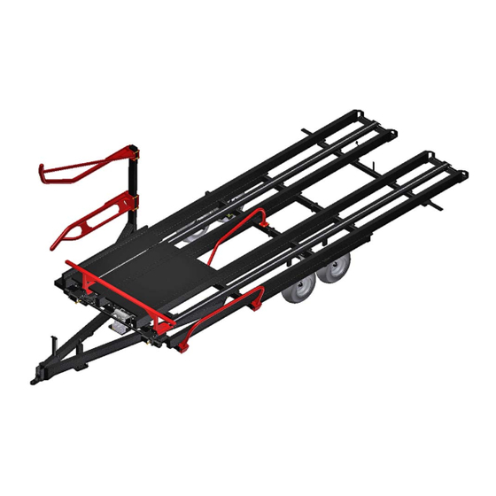
- Page 10 Introduction - Round Bale Carrier 2400 EQUIPMENT IDENTIFICATION Component Location RH FORK W / DEFLECTOR PUSHER BALE RETAINER BALE DIVERTER TIPPING FRAME MANUAL STORAGE CONTAINER HYDRAULIC MOTOR TAIL LIGHT ASSEMBLY INNER FORK CONTROL VALVE PICK UP ARM PICK UP ARM...
- Page 11 Safety - Round Bale Carrier 2400 SAFETY SAFETY INSTRUCTIONS ............13 Safe Operation Is The Operator’s Responsibility .
- Page 12 Safety - Round Bale Carrier 2400...
-
Page 13: Safety Instructions
Written Instructions, Rules unsafe practices. Regulations • The written instructions from Farm King include the Warranty Registration, Dealer Inspection Report, Operator And Parts Manual and machine signs (decals). • Check the rules and regulations at your location. The rules may include an employer’s work safety The signal word DANGER on the machine and in the requirements. -
Page 14: Use Safety Rules
Safety - Round Bale Carrier 2400 SAFETY INSTRUCTIONS (CONT’D) Transport Safety Use Safety Rules • DO NOT exceed 20 mph (32 kph). Reduce speed on • Read and follow instructions in this manual and the rough roads and surfaces. tractor’s Operators Manual before operating. -
Page 15: Machine Requirements And Capabilities
• Before leaving the operator’s position: Operation 1. Always park on a flat level surface. The Farm King machine must be in good operating 2. Place all controls in neutral. condition before use. 3. Engage the parking brake. 4. Stop engine. -
Page 16: Electrical
Safety - Round Bale Carrier 2400 Electrical Fire Extinguishers Check all electrical wiring and connections for damage. Keep the battery terminals clean and tight. Repair or replace any damaged part or wires that are loose or frayed. Know where fire extinguishers and first aid kits are Hydraulic System located and how to use them. -
Page 17: Safety Signs (Decals)
SAFETY SIGNS (DECALS) Follow the instructions on all the Signs (Decals) that are on the equipment. Replace any damaged signs (decals) and be sure they are in the correct locations. Equipment signs are available from your Farm King equipment dealer. Chain Shields... - Page 18 Safety - Round Bale Carrier 2400 Right Side Carrier Frame CAUTION SAFETY CHAIN MUST BE SECURED AND LOCKED FOR TRANSPORT. RELEASE ONLY FOR FIELD WORK. 813626 p/n 813626 B-10068 DANGER Bale lift arm can cause serious injury or death if person becomes trapped during arm return.
-
Page 19: Equipment Decals And Signs
Safety - Round Bale Carrier 2400 EQUIPMENT DECALS AND SIGNS Part Number 21867 NOTE: All safety related decals are shown in the Safety Signs Section. (See “SAFETY SIGNS (DECALS)” on page 17.) Check and replace any worn, torn, hard to read or Part Number 813633 missing decals on your equipment. -
Page 20: Safety Sign-Off Form
Farm King follows the general Safety Standards specified by the American Society of Agricultural and Biological Engineers (ASABE) and the Occupational Safety and Health Administration (OSHA). Anyone who will be operating and / or maintaining the 2400 Round Bale Carrier must read and clearly understand ALL Safety, Operating and Maintenance information presented in this manual. -
Page 21: Assembly
Assembly - Round Bale Carrier 2400 ASSEMBLY GENERAL ASSEMBLY INFORMATION ..........23 Component Unloading And Identification . - Page 22 Assembly - Round Bale Carrier 2400...
-
Page 23: General Assembly Information
Unload the crate(s) and components on a flat level area of adequate size to assemble the 2400 Round Bale Carrier components. Unload crate(s) and round bale carrier components carefully to prevent damage to any of the... -
Page 24: Base Group
Assemble the main frame on a flat level surface. is correct for all 2400 Round Bale Carriers. Always use chains, straps and lifting devices that are in good condition and of adequate size to lift the bale carrier components. - Page 25 Assembly - Round Bale Carrier 2400 Figure 4 Figure 5 B-10017 B-10018 Align and install the outer light bracket (Item 1) [Figure 4] Align and install the RH tail light (Item 1) [Figure 5] under the inner light bracket. (Amber lens to the outside) under the outer light bracket.
-
Page 26: Installing The Bale Retainer
Assembly - Round Bale Carrier 2400 Installing The Bale Retainer Figure 8 Figure 7 B-10027 Install three 1/2” x 2” bolt (Item 1) down through the bale retainer mounting bracket and carrier frame mount. B-10026 Install one 1/2” flat washer and 1/2” locknut (Item 2) [Figure 8] on each bolt. -
Page 27: Installing The Pick-Up Arm W / Bale Deflector
2400 Round Bale Carriers. Always use chains, straps and lifting devices that are in good condition and of adequate size to lift the bale carrier components. - Page 28 Assembly - Round Bale Carrier 2400 Figure 10 Figure 12 B-10033 B-10064 Move the pick-up arm to left front side of the carrier Install one 3/8” x 2-1/2” bolt (Item 1) [Figure 12] through frame. Align the two mounting brackets (Item 1) [Figure the collar and pin.
- Page 29 Assembly - Round Bale Carrier 2400 Figure 14 NOTE: When installing the 1-1/4 x 6-3/4 inch lift arm pivot pin, maintain hole alignment of the pin and collar on the pick up arm mounting bracket. Install one 1-1/4 x 6-3/4 inch lift arm pivot pin (Item 3)
- Page 30 Assembly - Round Bale Carrier 2400 Raise the pick up arm high enough to allow the RH fork Figure 20 with deflector to be placed under the pick up arm. Figure 18 B-10060 Locate inside fork arm (Item 1). Install straps (Item 2)
- Page 31 Assembly - Round Bale Carrier 2400 Figure 22 B-10062 Raise the inside fork arm (Item 1) up against the pick up arm (Item 2) [Figure 22]. Install two 5/8” x 6” bolts (Item 3) [Figure 22] through the inside fork arm mounting bracket (over the pick up arm) Install one 5/8”...
-
Page 32: Adjusting Pick Up Arm Forks
Assembly - Round Bale Carrier 2400 Adjusting Pick Up Arm Forks Lower the inner fork arm to the desired height above the carrier deck. Figure 23 Tighten the two 5/8” x 6” bolts to secure the inner fork arm to the pick up arm. -
Page 33: Operation
Operation - Round Bale Carrier 2400 OPERATION GENERAL INFORMATION ............35 Pre - Operation Checklist . - Page 34 Operation - Round Bale Carrier 2400...
-
Page 35: General Information
Operation - Round Bale Carrier 2400 4. Check that wheel bolt torque is 110 ft. lb. (149 Nm). GENERAL INFORMATION 5. Fully clean the equipment. (See “CLEANING THE Pre - Operation Checklist BALE CARRIER” on page 59.) Before operating the Bale Carrier for the first time and each time thereafter, check the following items: 6. -
Page 36: Break - In Checklist
Operation - Round Bale Carrier 2400 Break - In Checklist Check the following mechanical items after 1 hour of operation and again after 10 hours of operation: 1. Check condition of all hydraulic components for leaks. Tighten fittings correct leaks replace components. -
Page 37: Tractor Requirements
Keep away from moving parts. • Keep bystanders away. The 2400 Round Bale Carrier will require a tractor with minimum 80 hp (60 kw) and two pair of remote outlets (operate with either closed center or open center / load sensing hydraulic system). -
Page 38: Initial Set-Up
Operation - Round Bale Carrier 2400 Leaving The Operator’s Position INITIAL SET-UP Connecting The Bale Carrier To The Tractor Always inspect the tractor’s drawbar and Bale Carrier hitch before connecting. See the tractor’s owner’s manual. AVOID INJURY OR DEATH Verify that the tractor’s drawbar is adjusted correctly for Before you leave the operator’s position:... - Page 39 Operation - Round Bale Carrier 2400 Figure 28 Figure 29 B-2074 B-10051 Install the hitch pin (Item 1) [Figure 29] and retaining pin Turn the handle (Item 1) [Figure 28] clockwise to raise to securely fasten the Bale Carrier hitch to the tractor the hitch or counterclockwise to lower the hitch.
-
Page 40: Leveling The Bale Carrier
Operation - Round Bale Carrier 2400 Leveling The Bale Carrier The bale carrier frame must be adjusted down or up Place one support stand under the two hitch beams, until the bale carrier is parallel with the ground prior to evenly support the hitch beams. The two hitch to operation. -
Page 41: Connecting Hydraulic Lines
Operation - Round Bale Carrier 2400 Connecting Hydraulic Lines To Connect: Figure 32 HIGH PRESSURE FLUID HAZARD To prevent serious injury or death from high pressure fluid: • Relieve pressure on system before repairing or adjusting. B-10052 • Wear proper hand and eye protection when searching for leaks. -
Page 42: Connect Electrical Harness
Operation - Round Bale Carrier 2400 Connect Electrical Harness Control Handle Description Figure 33 Engage tractor auxiliary hydraulics. Figure 34 B-2057 Connect the Bale Carrier’s lighting harness (Item 1) [Figure 33] to the tractor’s electrical system. B-10011 1. PUSHER SPEED Press PUSHER SPEED switch UP (Rabbit) to operate pusher at a high speed. -
Page 43: Loading Procedure
Operation - Round Bale Carrier 2400 Loading Procedure Empty / Full Indicator Figure 35 CARRIER DECK EMPTY CARRIER DECK FULL Before operating the equipment: • Clear the work area of all bystanders, especially small children. • Clear the work area of all obstacles. - Page 44 Operation - Round Bale Carrier 2400 End On Bale Pick-Up Press and hold the ARM DN switch and fully lower the lift arm. Move the tractor and bale carrier straight forward drive so the inner arm of the loading fork is against the inner edge of the next bale.
-
Page 45: Optional Bale Stop
Operation - Round Bale Carrier 2400 Side On Bale Pick-Up Press and hold the ARM DN switch and fully lower the lift arm. Move the tractor and bale carrier straight forward until the deflector contacts the second bale (Side-On) about 12 inches (30 cm) from the outer end (rotating bale 90°. -
Page 46: Unloading Procedure
Operation - Round Bale Carrier 2400 Unloading Procedure Figure 39 ELECTROCUTION HAZARD prevent serious injury death from electrocution, stay at least 50 ft. (15 m) away from overhead power line when raising tipping frame or lift arm. B-10009 Using the tractor auxiliary hydraulics, raise the tipping frame until the frame is slightly off the ground [Figure 39]. -
Page 47: Transporting
Operation - Round Bale Carrier 2400 TRANSPORTING Requirements Comply with federal, state, local and provincial laws regarding the transport of farm equipment on public roadways. Do not transport if rear bales are overhanging rear of carrier deck. Rear of carrier deck should extend beyond rear bales for a minimum of 2 ft. - Page 48 Operation - Round Bale Carrier 2400...
-
Page 49: Maintenance
Maintenance - Round Bale Carrier 2400 MAINTENANCE TROUBLESHOOTING ............51 General Chart . - Page 50 Maintenance - Round Bale Carrier 2400...
-
Page 51: Troubleshooting
Maintenance - Round Bale Carrier 2400 TROUBLESHOOTING General Chart Instructions are necessary before operating or servicing equipment. Read and understand the Operator And Parts Manual and safety signs (decals) on equipment. Follow warnings and instructions in the manuals when making repairs, adjustments or servicing. Check for correct function after adjustments, repairs or service. -
Page 52: Service Schedule
Maintenance work must be done at regular intervals. Failure to do so will result in excessive wear and early failures. The service schedule is a guide for correct maintenance of the 2400 Round Bale Carrier. Instructions are necessary before operating or servicing equipment. Read and understand the Operator and Parts Manual and safety signs (decals) on equipment. -
Page 53: Lubrication
Maintenance - Round Bale Carrier 2400 LUBRICATION Locations Recommendations Always use a good quality multi-purpose / lithium base grease when lubricating the equipment. Fluid such as engine oil, hydraulic fluid, coolants, grease, etc. must disposed environmentally safe manner. Some regulations require that certain spills and leaks on the ground must be cleaned in a specific manner. - Page 54 Maintenance - Round Bale Carrier 2400 Figure 42 Figure 44 B-10042 B-10023 Apply two - three pumps of grease to both ends of the Apply two - three pumps of grease to the LH & RH hitch bale lift arm cylinder (Item 1) [Figure 42].
-
Page 55: Pusher Chain And Sprocket
Maintenance - Round Bale Carrier 2400 Lubricate the following grease locations EVERY 50 PUSHER CHAIN AND SPROCKET HOURS: Inspection Figure 46 AVOID INJURY OR DEATH Before you leave the operator’s position: • Always park on a flat level surface. •... -
Page 56: Adjusting Chain Tension
Maintenance - Round Bale Carrier 2400 Adjusting Chain Tension Figure 48 AVOID INJURY OR DEATH Before you leave the operator’s position: • Always park on a flat level surface. • Place all controls in NEUTRAL. • Engage the park brake. -
Page 57: Shortening The Pusher Chain
Maintenance - Round Bale Carrier 2400 Shortening The Pusher Chain Figure 51 AVOID INJURY OR DEATH Before you leave the operator’s position: • Always park on a flat level surface. • Place all controls in NEUTRAL. • Engage the park brake. -
Page 58: Axle
Maintenance - Round Bale Carrier 2400 AXLE Remove the six wheel bolts and remove the tire / wheel. Wheel Bolts Torque Figure 53 Check the torque on wheel bolts daily. Tighten wheel bolts to 110 lb. / ft. (149 N•m) torque. -
Page 59: Cleaning The Bale Carrier
Maintenance - Round Bale Carrier 2400 CLEANING THE BALE CARRIER SAFETY SIGN (DECAL) INSTALLATION Fully Clean the Bale Carrier EVERY 50 HOURS: Procedure Keep the bale carrier free of any hay or straw build up, especially keep all electrical and hydraulic components clear. -
Page 60: Storage And Return To Service
STORAGE AND RETURN TO SERVICE Return To Service Storage After the Farm King Bale Carrier has been in storage, it is necessary to follow a list of items to return the equipment Sometimes it may be necessary to store your Farm King to service. -
Page 61: Parts Identification
Parts Identification - Round Bale Carrier 2400 PARTS IDENTIFICATION GENERAL INFORMATION ............63 BASE FRAME . - Page 62 Parts Identification - Round Bale Carrier 2400...
-
Page 63: General Information
Parts - Round Bale Carrier 2400 GENERAL INFORMATION The parts identification section lists descriptions, part numbers and quantities for the Round Bale Carrier 2400. Contact your Farm King dealer for additional Round Bale Carrier 2400 parts information. BASE FRAME Carrier Hydraulic Assembly... -
Page 64: Valve Bank Assembly
Parts - Round Bale Carrier 2400 Valve Bank Assembly 815846 ITEM PART NUMBER DESCRIPTION 815296 VALVE MANIFOLD 83000074 STRAIGHT ADAPTER, 3/4” MJIC x 1-1/16” MORB 83000073 STRAIGHT ADAPTER, 9/16” MJIC x 7/8” MORB 886897 STRAIGHT ADAPTER, 7/8” MORB x 3/4” MJIC... - Page 65 Parts - Round Bale Carrier 2400 Manifold Service Parts A7010-00 ITEM PART NUMBER DESCRIPTION SZ000523 SVP, 10 - NO - 12 - DN - B SZ000524 COIL SZ000525 COIL NUT KIT SZ000516 SEAL KIT SZ000526 DCV05 - 2C1 1 / 01200E1...
- Page 66 Parts - Round Bale Carrier 2400 Manifold Hydraulic Schematic 83000055...
-
Page 67: High Pressure Line Assembly
Parts - Round Bale Carrier 2400 High Pressure Line Assembly 815822 ITEM PART NUMBER DESCRIPTION 815824 HYDRAULIC HOSE, 1/2” x 142-7/8” MORB x 3/4” SWIVEL FJIC 90° 815177 MALE TIP, 0.5” BODY 7/8” ORB 813305 BLACK DUST CAP, 1/2” Hydraulic Return Line Assembly... -
Page 68: Tilt Cylinder Extend Hydraulic Hose Assembly
Parts - Round Bale Carrier 2400 Tilt Cylinder Extend Hydraulic Hose Assembly 815612 ITEM PART NUMBER DESCRIPTION 815613 HYDRAULIC HOSE, 3/8” x 192-7/8” MORB x 3/4” SWIVEL FJIC 90° 813303 RED DUST CAP, 0.5” 815177 MALE TIP, 0.5” BODY 7/8” ORB... -
Page 69: Lift Arm Cylinder Assembly
Parts - Round Bale Carrier 2400 Lift Arm Cylinder Assembly 815803 ITEM PART NUMBER DESCRIPTION 815804M CYLINDER, 4.0” x 12.0” 886897 STRAIGHT ADAPTER, 7/8” MORB x 3/4” MJIC 815804M SERVICE PARTS X3916 SEAL KIT Tilt Cylinder Assembly 815839 ITEM PART NUMBER... -
Page 70: Pusher Motor Assembly
Parts - Round Bale Carrier 2400 Pusher Motor Assembly 815679 ITEM PART NUMBER DESCRIPTION B2799-00 MOTOR, 22.2 CUBIC INCH 886897 STRAIGHT ADAPTER, 7/8” MORB x 3/4” MJIC B2799-00 SERVICE PARTS X2725 SEAL KIT... -
Page 71: Hydraulic Assembly Hardware
Parts - Round Bale Carrier 2400 Hydraulic Assembly Hardware HYD HARDWARE ITEM PART NUMBER DESCRIPTION 112954 PIN, 1.25” DIA. x 6.75” LG 113698 PIN, 1.25” DIA. x 7.13” LG 812363 LOCK NUT, 0.375” GRB (STEEL) (PL) 813663 LOCK NUT, 0.500” NC GRC (STEEL) (PL) -
Page 72: Frame Assembly (Top View)
Parts - Round Bale Carrier 2400 Frame Assembly (Top View) 3, 15, 26 20, 16, 16, 4 3, 15, 26 19, 2, 18 20, 16, 16, 4 21, 16, 16, 4 817527-TOP... - Page 73 Parts - Round Bale Carrier 2400 ITEM PART NUMBER DESCRIPTION 811795 BOLT, 3/8” x 2” HEX (PL) 812026 BOLT, 5/16” x 1” HEX (PL) 813643 CONNECTOR LINK, HD C2080 813663 NUT LOCK, 0.500” NC (STEEL) GR C (PL) 815689 BALE DIVERTER...
-
Page 74: Frame Assembly (Bottom View)
Parts - Round Bale Carrier 2400 Frame Assembly (Bottom View) 8, 3, 6 2, 6, 3 1, 6, 3 817527-BOTTOM... - Page 75 Parts - Round Bale Carrier 2400 ITEM PART NUMBER DESCRIPTION 112954 PIN, 1.25” x 6.75” LG 113698 PIN, 1.25” x 7.13” LG LDR 86015933 812363 LOCK NUT, 3/8” (PL) 815379 PIN, 1.25” x 3.75” LG 815803 CYLINDER ASSEMBLY, 4” x 12”...
-
Page 76: Carrier Frame Assembly
Parts - Round Bale Carrier 2400 Carrier Frame Assembly 6, 22, 37 7, 8, 8, 9 39, 35, 35, 11 4, 11 11, 35, 35, 38 11, 35, 35, 38 11, 35, 35, 39 6, 22, 3 11, 35, 39... - Page 77 Parts - Round Bale Carrier 2400 ITEM PART NUMBER DESCRIPTION 21417 CABLE CLAMP, 1/8” 28556 SAFETY LOCK SPRING 811795 BOLT, 3/8” x 2” HEX (PL) 812217 CARRIAGE BOLT, 1/2” x 1-1/2” (PL) 812362 LOCK NUT, 5/16” (PL) 812363 LOCK NUT, 3/8” (PL) 812482 LOCK NUT, 5/8”...
-
Page 78: Electrical Assembly
Parts - Round Bale Carrier 2400 Electrical Assembly 2, 1 2, 1 3, 10 9, 10 3, 10 815603... - Page 79 Parts - Round Bale Carrier 2400 ITEM PART NUMBER DESCRIPTION 812537 LOCK NUT, 0.136” NC (NYLON) GR B PL 813958 MACHINE SCREW, #8-32 x 0.75” FLAT HD 814063 WIRING HARNESS CLAMP 814193 ENHANCED AG LIGHTING MODULE 814195 RH DUAL / AG / LAMP, 4-WAY WP...
-
Page 80: Electrical Schematic (Prior To S/N Bm240013000061)
Parts - Round Bale Carrier 2400 Electrical Schematic (Prior to S/N BM240013000061) ROCKER SWITCH GROUND 12 - GREEN LOW SPEED 1 - BLACK PUSHER FWD. 7 - BROWN PUSHER BACK 6 - BLUE ARM DN. 2 - TAN NOTE: ARM UP 4 - PINK... -
Page 81: Electrical Schematic (2018 And Later)
Parts - Round Bale Carrier 2400 Electrical Schematic (2018 and later) -
Page 82: Control Handle Assembly
Parts - Round Bale Carrier 2400 Control Handle Assembly I20024_00 ITEM PART NUMBER DESCRIPTION 22105 CONTROL HANDLE 813540 SCREW, 8-32 x 0.50” 815851 SWITCH COVER DECAL - 2400 I100016 SWITCH COVER PLATE - 2400 INE22105-01 WIRE CLAMP PLATE 815382 ROCKER SWITCH ON - OFF... -
Page 83: Tire Assembly
Parts - Round Bale Carrier 2400 Tire Assembly B2700-03 ITEM PART NUMBER DESCRIPTION 813657 TIRE, 12.5L x 15FI 813655 RIM, 15 x 10LB x 6 BOLT P65 813656 VALVE STEM / TUBELESS RIM... -
Page 84: Tandem Axle Assembly W / Two Hubs
Parts - Round Bale Carrier 2400 Tandem Axle Assembly W / Two Hubs 815686 ITEM PART NUMBER DESCRIPTION 815687 TANDEM AXLE WELDMENT, W / TWO HUBS C2339-00 6 BOLT HUB 13651 FLAT WASHER, 2.0” x 1.03” x 0.19” W / HUB... -
Page 85: Tandem Axle Assembly W / Four Hubs
Parts - Round Bale Carrier 2400 Tandem Axle Assembly W / Four Hubs B2722-00 ITEM PART NUMBER DESCRIPTION C2722-00 TANDEM AXLE WELDMENT, W / FOUR HUBS C2339-00 6 BOLT HUB 13651 FLAT WASHER, 2.0” x 1.03” x 0.19” W / HUB... -
Page 86: Hub Assembly
Parts - Round Bale Carrier 2400 Hub Assembly C2339-00_REV_2 ITEM PART NUMBER DESCRIPTION 967204 OIL SEAL, 9CTD - SE30 967208 OUTER BEARING CONE (LM48548) 813653 BOLT, 0.563” NF x 1.75” (WB12) / HUB 813650 DUST CAP DC15 813649 DUST SHIELD DC16... -
Page 87: Pusher Assembly
Parts - Round Bale Carrier 2400 Pusher Assembly 817540 ITEM PART NUMBER DESCRIPTION 811795 BOLT, 3/8” x 2” HEX (PL) 812363 LOCK NUT, 3/8” (PL)” 813644 MACHINE SCREW, 0.313” NC x 1.25” RD HD 81570 FLAT WASHER, 0.375” ST HS (PL) -
Page 88: Roller / Chain Guide Assembly
Parts - Round Bale Carrier 2400 Roller / Chain Guide Assembly A7008-00 ITEM PART NUMBER DESCRIPTION INE7037-00 ROLLER / CHAIN GUIDE 813645 BEARING, 6205LLU / 25.4 / 3E... -
Page 89: Pick Up Arm W / Deflector Assembly
Parts - Round Bale Carrier 2400 Pick Up Arm W / Deflector Assembly 13, 6 8, 3 815709 ITEM PART NUMBER DESCRIPTION 112954 PIN, 1.25” DIA. x 6.75” LG 812087 BOLT, 5/8” x 6” HEX (PL) 812363 LOCK NUT, 3/8” (PL) 812639 FLAT WASHER 0.625”... -
Page 90: Hitch Assembly
Parts - Round Bale Carrier 2400 Hitch Assembly 11, 12 10, 11 7, 8, 12 4, 5 815699 ITEM PART NUMBER DESCRIPTION 815706-26 RH HITCH WELDMENT 815702-26 LH HITCH WELDMENT 00047589 BOLT, 0.750” NC x 6” LG HEX GR 8 (PL) 813648 LOCK NUT, 0.750”... -
Page 91: Optional Adjustable Bale Stop Assembly
Parts - Round Bale Carrier 2400 Optional Adjustable Bale Stop Assembly 815692 ITEM PART NUMBER DESCRIPTION 815693 BALE STOP BRACKET 12779 HAIRPIN CLIP #9 815696 BALE STOP WELDMENT 815416 VALVE MOUNT U-BOLT 84048 FLAT WASHER, 0.500” SAE BS (PL) 813663 LOCK NUT, 0.500”... -
Page 92: Standard Hitch Assembly
Parts - Round Bale Carrier 2400 Standard Hitch Assembly SZ000561 ITEM PART NUMBER DESCRIPTION SZ000569 TOP PLATE SZ000570 V-BLOCK SZ000571 NEOPRENE CUSHIONS... -
Page 93: Optional Clevis Hitch Assembly
Parts - Round Bale Carrier 2400 Optional Clevis Hitch Assembly SZ000513 ITEM PART NUMBER DESCRIPTION SZ000513 OPTION CLEVIS HITCH KIT... - Page 94 Parts - Round Bale Carrier 2400...
-
Page 95: Specifications
Specifications - Round Bale Carrier 2400 SPECIFICATIONS SPECIFICATIONS ............. . 97 Dimensions . - Page 96 Specifications - Round Bale Carrier 2400...
-
Page 97: Specifications
Specifications - Round Bale Carrier 2400 SPECIFICATIONS Dimensions DESCRIPTION 2400 Overall Length 34’ (10.4 m) Usable Deck Length 24’ (7.3 m) Maximum Overall Width 22’ (6.7 m) Transport Width 12’ 7” (3.8 m) Overall Height 12’ 10” (3.9 m) Deck Height 3’... -
Page 98: Hydraulic Schematic
Specifications - Round Bale Carrier 2400 HYDRAULIC SCHEMATIC 83000055... -
Page 99: Electrical Schematic
Specifications - Round Bale Carrier 2400 ELECTRICAL SCHEMATIC Electrical Schematic (Prior to S/N BM240013000061) ROCKER SWITCH GROUND 12 - GREEN LOW SPEED 1 - BLACK PUSHER FWD. 7 - BROWN PUSHER BACK 6 - BLUE ARM DN. 2 - TAN... -
Page 100: Electrical Schematic (S/N Bm240013000061 And Later)
Specifications - Round Bale Carrier 2400 Electrical Schematic (2018 and later) -
Page 101: Hardware Torque Values
Specifications - Round Bale Carrier 2400 HARDWARE TORQUE VALUES Metric Chart NOTE: Do not use the values listed in the charts if a different torque value or tightening procedure is specified in this manual for a specific application. Torque values listed are for general use only. -
Page 102: Imperial Chart
Specifications - Round Bale Carrier 2400 HARDWARE TORQUE VALUES (CONT’D) Imperial Chart NOTE: Do not use the values listed in the charts if a different torque value or tightening procedure is specified in this manual for a specific application. Torque values listed are for general use only. -
Page 103: Hydraulic Connection Specifications
Specifications - Round Bale Carrier 2400 HYDRAULIC CONNECTION SPECIFICATIONS Port Seal (O-ring Boss) Fitting O-Ring Fitting (Straight Thread) Figure 56 Lubricate the O-ring before installing the fitting. Loosen Port Seal And O-ring Boss Tightening Torque the jam nut and install the fitting. Tighten the jam nut until the washer is tight against the surface. - Page 104 Specifications - Round Bale Carrier 2400...
-
Page 105: Warranty
Warranty - Round Bale Carrier 2400 WARRANTY WARRANTY ..............107... - Page 106 Warranty - Round Bale Carrier 2400...
- Page 107 If Farm King determines that it will pay labor costs for warranty work, it will do so by issuing a credit to the dealer’s or distributor’s account.
- Page 108 Limited Warranty WARRANTY REQUIREMENTS To be covered by warranty, each new product must be registered with Farm King within thirty (30) days of delivery to original retail purchaser. If the customer decides to purchase replacement components before the warranty disposition of such components is determined, Farm King will bill the customer for such components and then credit the replacement invoice for those components later determined to be covered by this limited warranty.
-
Page 109: Alphabetical Index
Alphabetical Index - Round Bale Carrier 2400 ALPHABETICAL INDEX AXLE ......58 BALE STORAGE . - Page 110 Alphabetical Index - Round Bale Carrier 2400...
- Page 112 www.farm-king.com 411 Center Avenue West Salem, SD USA 57058-0398 Toll Free: 1-888-FK-80001 E-mail: info@buhler.com www.farm-king.com Equipment shown is subject to change without notice. ©2012 Buhler Trading Inc. Printed in Canada TSX:BUI...
Need help?
Do you have a question about the 2400 and is the answer not in the manual?
Questions and answers