
Related Manuals for Farm King Model 1050


Summary of Contents for Farm King Model 1050
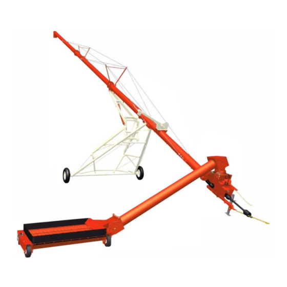
- Page 1 OPERATOR AND PARTS MANUAL Backsaver Auger Model 1050, 1060, 1070 and 1080 082014 Revision 1 FK306 6990633 (1-13) Printed in U.S.A. © Bobcat Company 2013 062013 | Rev 1 | 88664296...
-
Page 3: Table Of Contents
Table of Contents - 10" Backsaver Auger TABLE OF CONTENTS Manufacturer’s Statement: For technical reasons, Buhler Industries Inc. reserves the right to modify machinery design and specifications provided herein without any preliminary notice. Information provided herein is of descriptive nature. Performance quality may depend on soil fertility, applied agricultural techniques, weather INTRODUCTION . - Page 4 Table of Contents - 10" Backsaver Auger...
-
Page 5: Safety
Customer / Owner’s Signature: Remove this Warranty Registration Form from the Operator And Parts Manual. Make two copies of the form. Send original Warranty Registration Form to Farm King. Give one copy to the customer and the dealer will keep one copy. - Page 6 Warranty Registration - 10" Backsaver Auger...
-
Page 7: Introduction
Farm King equipment. READ AND UNDERSTAND THIS OPERATOR AND PARTS MANUAL BEFORE OPERATING YOUR FARM KING EQUIPMENT. If you have any questions, see your Farm King dealer. This manual may illustrate options and accessories not installed on your Farm King equipment. - Page 8 Introduction - 10" Backsaver Auger...
-
Page 9: Owner's Information
Introduction - 10" Backsaver Auger Serial Number Location OWNER’S INFORMATION Thank you for your decision to purchase a Farm King Please enter the model and serial number in the space Backsaver Auger. To ensure maximum performance of provided for easy reference. -
Page 10: Assembly
Introduction - 10" Backsaver Auger EQUIPMENT IDENTIFICATION Component Location BRIDGING YOKE BRIDGING CABLE BRIDGING YOKE INTAKE LIFT BOOM DISCHARGE SPOUT INPUT BOX ELBOW TUBE ASSEMBLY HYDRAULC HOSE HOLDER LIFT CYLINDER UNDERCARRIAGE ASSEMBLY PTO HOLDER CHAIN DRIVELINE MANUAL JACK STORAGE HITCH HITCH SAFETY HOPPER CHAIN... - Page 11 Safety - 10" Backsaver Auger SAFETY SAFETY INSTRUCTIONS ..........11 Safe Operation Is The Operator’s Responsibility .
- Page 12 Safety - 10" Backsaver Auger...
-
Page 13: Safety Instructions
It may also be used to alert against Understand the Written Instructions, Rules and unsafe practices. Regulations • The written instructions from Farm King include the Warranty Registration, Dealer Inspection Report, Operator And Parts Manual and machine signs (decals). •... -
Page 14: Use Safety Rules
Safety - 10" Backsaver Auger SAFETY INSTRUCTIONS (CONT’D) Transport Safety Use Safety Rules • Do not exceed 20 mph (32 kph). Reduce speed on • Read and follow instructions in this manual and the rough roads and surfaces. tractor’s Operators Manual before operating. •... -
Page 15: Safety Rules For Power Take-Off (Pto) Driven Equipment
Safety - 10" Backsaver Auger SAFETY INSTRUCTIONS (CONT’D) • Keep bystanders clear of moving parts and the work area. Keep children away. Safety Rules For Power Take-Off (PTO) Driven Equipment • Use increased caution on slopes and near banks and ditches to prevent overturn. •... -
Page 16: Operation
Fueling Operation The Farm King machine must be in good operating condition before use. Check all of the items listed on the service schedule under the 8 hour column. (See “SERVICE SCHEDULE” Stop the engine and let it cool before adding fuel. No on page 88.) -
Page 17: Welding And Grinding
Safety - 10" Backsaver Auger FIRE PREVENTION (CONT’D) Welding And Grinding Always clean the machine and equipment, disconnect the battery, and disconnect the wiring from the machine controls before welding. Cover rubber hoses, battery and all other flammable parts. Keep a fire extinguisher near the machine when welding. -
Page 18: Operating Safety Zone
Safety - 10" Backsaver Auger OPERATING SAFETY ZONE Safety Zone Identification ELECTROCUTION HAZARD • Owners operators Keep away from power lines, AVOID INJURY OR DEATH should allow only electrocution occur authorized personnel and • allow small without direct contact. grain transport vehicles children,... -
Page 19: Safety Signs (Decals)
SAFETY SIGNS (DECALS) Follow the instructions on all the Signs (Decals) that are on the equipment. Replace any damaged signs (decals) and be sure they are in the correct locations. Equipment signs are available from your Farm King equipment dealer. - Page 20 Safety - 10" Backsaver Auger SAFETY SIGNS (DECALS) (CONT’D) Intake Auger Input Box Elbow / Cover B-0502 B-0714 p/n 961016 p/n 963206...
- Page 21 Safety - 10" Backsaver Auger SAFETY SIGNS (DECALS) (CONT’D) Intake Auger B-0738 p/n 917765 p/n 961017...
-
Page 22: Equipment Decals And Signs
Safety - 10" Backsaver Auger EQUIPMENT DECALS AND SIGNS Part Number 960372 NOTE: All safety related decals are shown in the Safety Signs Section. (See “SAFETY SIGNS (DECALS)” on page 17.) Check and replace any worn, torn, hard to read or missing decals on your equipment. -
Page 23: Safety Sign-Off Form
Untrained operators and failure to follow instructions can cause injury or death. Farm King follows the general Safety Standards specified by the American Society of Agricultural and Biological Engineers (ASABE) and the Occupational Safety and Health Administration (OSHA). Anyone who will be operating and / or maintaining the Backsaver Auger must read and clearly understand ALL Safety, Operating and Maintenance information presented in this manual. - Page 24 Safety - 10" Backsaver Auger...
- Page 25 Assembly - 10" Backsaver Auger ASSEMBLY GENERAL ASSEMBLY INFORMATION ........25 Component Unloading And Identification .
- Page 26 Assembly - 10" Backsaver Auger...
-
Page 27: General Assembly Information
GENERAL ASSEMBLY INFORMATION NOTE: If any components are damaged, missing or replacement parts are required, contact your Component Unloading And Identification Farm King Dealer. Assemble the 10” Backsaver Auger in the following order: 1. Undercarriage (See “Undercarriage Assembly” on page 26.) -
Page 28: Base Group
Assembly - 10" Backsaver Auger BASE GROUP Figure 4 Undercarriage Assembly Assemble the undercarriage on a flat level surface. B-0583 Install a strap (Item 1) around the center of the axle • DO NOT permit bystanders to be in the work area (Item 2) [Figure 4]. - Page 29 Assembly - 10" Backsaver Auger Figure 6 Figure 8 B-0587 B-0590 Align the left undercarriage arm (Item 1) with the tab Install the tire with the valve stem facing out (both (Item 2) [Figure 6] on the axle. sides). Install the five wheel nuts (both sides) [Figure Install two 3/8”...
- Page 30 Assembly - 10" Backsaver Auger Figure 9 Figure 11 B-0596 B-0592 Align the LH undercarriage arch (Item 1) [Figure 11], Align the undercarriage tie plate (Item 1) [Figure 9] on the outside of the mounts on the undercarriage arm with mounting plates &...
- Page 31 Assembly - 10" Backsaver Auger Figure 13 Figure 15 B-0598 B-0600 Align and lower the lower lift arm (Item 1) down onto Locate and install the lift arm cradle (Item 1) [Figure the top mounting bracket (Item 2) [Figure 15] on the 13] onto the bottom of LH &...
- Page 32 Assembly - 10" Backsaver Auger Figure 16 Figure 18 EARLIER MODELS EARLIER MODELS B-0602 B-0603 Align and install the lower lift arm (Item 1) between the LH & RH lower lift arms using eight 5/8” x 1-3/4” Install the lift cross member (Item 1) between the LH bolts (Item 2) [Figure 16] and eight 5/8”...
- Page 33 Top Cylinder Pin Sizes Lift Arm Clevis Pin Sizes 1” x 6-1/2” - Model 1050 1” x 2-13/16” - Model 1050 & 1060 1” x 6-7/8” - Model 1060 1-1/4” x 2-13/16” - Model 1070 1-1/4” x 7-3/4” - Model 1070...
- Page 34 1” x 22” - Model 1060 Figure 26 1-1/4” x 26” - Model 1070 Cotter Pin Sizes 3/16” x 1-1/2” - Model 1050 & 1060 1/4” x 2” - Model 1070 Figure 24 B-0615 Locate the pivot yoke weldment (Item 1) and yoke pin (Item 2) [Figure 26].
- Page 35 Connecting Link Swivel Pin Sizes [Figure 27]. 1” x 5-1/2” - Model 1050 & 1060 Install the yoke pin (Item 1) through the upper lift arm and pivot yoke weldment. Install one 1-1/4” x 10 ga.
-
Page 36: Tube Assembly
Assembly - 10" Backsaver Auger Tube Assembly Figure 30 Assemble the tube on a flat level surface. • DO NOT permit bystanders to be in the work area B-0607 when unloading and assembling the auger components. • DO NOT work under suspended parts. Install a strap (Item 1) around top tube section (Item 2) [Figure 30]. - Page 37 Assembly - 10" Backsaver Auger Figure 32 Figure 34 B-0609 B-0633 Align the mounting flanges of the top tube section Remove the cotter pin (Item 1) and loosen the castle (Item 1) and center tube section (Item 2) [Figure 32]. nut (Item 2) [Figure 34].
- Page 38 Repeat [Figure 35] & [Figure 36] for the bottom tube section. Locate and uncoil the four cables. Cable Sizes 3/8” - Model 1050 & 1060 1/2” - Model 1070 B-0627 Place one long and one short cable on each side of the tube assembly (longest cable towards the outside).
- Page 39 Assembly - 10" Backsaver Auger Figure 39 Figure 41 B-0628 B-0632 Install a strap (Item 1) on the bottom tube section, forward of the main bridging yoke mounting brackets Locate and install the splined shaft (Item 1) into the (Item 2) [Figure 39]. bottom tube section flighting, using two 1/2”...
- Page 40 Assembly - 10" Backsaver Auger Figure 43 Figure 45 B-0631 B-0636 NOTE: When installing the input box onto the Install a chain (Item 1) [Figure 43] onto the input box. flighting, guide the splined shaft through the opening on the opposite end of the input box. Connect the chain to an approved lifting device.
- Page 41 Assembly - 10" Backsaver Auger Figure 47 Figure 49 B-0639 B-0681 Install the second bearing flange (Item 1) [Figure 47] Install the 5/16” x 58 mm key (Item 1) [Figure 49]. over the drive stub shaft and 1-3/8” bearing. Align the mounting holes of the two bearing flanges.
- Page 42 Assembly - 10" Backsaver Auger Figure 51 Figure 53 B-0644 B-0646 Place a straight edge (Item 1) along side the three Install the connecting link (Item 1) through the two sprockets. Align sprocket (Item 2) [Figure 51] with the ends of the chain. Install the connecting link plate two pre-installed sprockets.
- Page 43 Assembly - 10" Backsaver Auger Figure 55 Figure 57 B-0631A B-0633 Install chain guard (Item 1) [Figure 55]. With the tube assembly complete, tighten the castle nut (Item 1) [Figure 57] just enough to install the Figure 56 cotter pin (Should feel a little tension on the flighting). NOTE: Bag of hardware for the tube supplies an extra cotter pin to replace the one removed by the castle nut when the tube assembly started.
- Page 44 Assembly - 10" Backsaver Auger Figure 59 Figure 61 B-0652 B-0657 Align the intake lift boom (Item 1) with the mounting Install one 1/2” cable clamp (Item 1) [Figure 61] plate on the bottom tube section. Install four 1/2” x 1- around the long cable, then install into the upper 1/2”...
- Page 45 Assembly - 10" Backsaver Auger Figure 62 Figure 63 B-0653 B-0659 Locate two cable yoke brackets (Item 1) [Figure 62]. Raise input box end of tube approximately three feet off the ground. Install the cable loop into the end of the cable yoke Locate one eyebolt (Item 1) [Figure 63].
- Page 46 Assembly - 10" Backsaver Auger Figure 64 Figure 65 B-0672 B-0368 NOTE: Cable lengths may vary. The following is a starting point and cables may need to be Place a mark (Item 1) [Figure 64] on the cable tightened more or loosened depending on the tightening tool.
-
Page 47: Installing Tube On Undercarriage
Assembly - 10" Backsaver Auger Figure 66 Installing Tube On Undercarriage Install the tube on the undercarriage on a flat level surface. B-0662 • DO NOT permit bystanders to be in the work area when unloading and assembling the auger components. - Page 48 Assembly - 10" Backsaver Auger Figure 67 Figure 69 B-0376A B-0663 With the strap (Item 1) [Figure 67] installed around the Align the RH & LH undercarriage arms with the center tube section and connected to an approved mounts (Item 1) [Figure 69] on the bottom tube lifting device, raise the tube assembly high enough to section (both sides).
- Page 49 NOTE: Loosening the lift arm cradle will allow the RH & LH undercarriage arms to be moved during Lift Arm Pivot Pin Sizes installation to the tube assembly. 1” x 11-7/8” - Model 1050 & 1060 Figure 72 1-1/4” x 12-1/4” - Model 1070 Cotter Pin Sizes 3/16”...
-
Page 50: Installing The Intake Auger
Assembly - 10" Backsaver Auger Figure 74 Grease zerks undercarriage. (See “LUBRICATION” on page 89.) Check over undercarriage, verify all bolts are tight, all zerks are greased and cotter pins bent over. Installing The Intake Auger NOTE: The following images may not show your exact intake auger as it appears but the procedure is correct. - Page 51 Assembly - 10" Backsaver Auger Figure 77 Figure 79 B-0708 B-0715 Install the input box pivot (Item 1) inside the four 1/4” Install the intake spacer (Item 1) [Figure 77] on the x 13/32” ID x 1-1/4” OD washers. Align the mounting top of the input box.
- Page 52 Assembly - 10" Backsaver Auger Figure 80 Figure 82 B-0462 B-0461 B-0460 Install a strap (Item 1) [Figure 80] around the intake Align the hole of intake auger mounting plate (Item 1) auger. and the hole of intake box mounting plate (Item 2) [Figure 82] (both sides).
- Page 53 Assembly - 10" Backsaver Auger Figure 84 B-0714 Slide the plastic sleeve (Item 1) up onto the intake auger. Install the clamp (Item 2) [Figure 84] and tighten to secure the plastic sleeve to the intake auger. Remove the strap and lifting device.
-
Page 54: Hopper Assembly And Installation
Assembly - 10" Backsaver Auger Hopper Assembly And Installation Figure 87 NOTE: The following images may not show your exact hopper components as they appear but the procedure is correct. Figure 85 B-0451 Align the two-hole rubber reinforcement (Item 1) [Figure 87] with holes in the rubber edge and outer B-0448 hopper flange. - Page 55 Assembly - 10" Backsaver Auger Figure 88 Figure 90 B-0725 B-0731 Install a ratchet strap (Item 1) onto the bracket (Item Align the mounting holes on the hopper and intake 2) [Figure 88] on the top of the hopper (connect the auger.
-
Page 56: Safety Chain Installation
Assembly - 10" Backsaver Auger Figure 92 Hydraulic Hose Holder Installation Figure 94 B-0734 B-0722 Align the hinged intake auger cover (Item 1) with the four mounting holes in the hopper. Install four 5/16” x Install the hydraulic hose holder (Item 1) [Figure 94] 1”... -
Page 57: Jack Installation
Assembly - 10" Backsaver Auger Jack Installation Hand Winch And Cable Installation Figure 96 Figure 98 B-0728 B-0716 Align and install the jack (Item 1) [Figure 96] onto the Install the hand winch mounting bracket (Item 1) hitch (hopper side). [Figure 98] on the opposite side of the hopper. - Page 58 Assembly - 10" Backsaver Auger bracket. Install one 7/16” flat washer and 3/8” lock Figure 101 nut on the three bolts. Tighten bolts and nuts. Figure 100 B-0741 Locate the winch cable. Install the open end of the B-0719 cable (Item 1) [Figure 101] over the pulley on the top of the lift boom.
-
Page 59: Hopper Safety Hook Installation
Assembly - 10" Backsaver Auger Hopper Safety Hook Installation Figure 104 Do not remove the drum to install the cable. Figure 103 B-0748 Install the quick link (Item 1) through the eye of the hook (Item 2) [Figure 104]. Install the quick link onto the safety chain at the desired location. -
Page 60: Hydraulic Assembly
Assembly - 10" Backsaver Auger HYDRAULIC ASSEMBLY NOTE: Apply teflon tape to the male threads of each fitting. Hydraulic Cylinder Hose Installation Install the 08 MNPT x 08 MNPT straight adaptor into the flow control valve [Figure 105]. Install the 08 MORB x 08 SWFNPT 45° elbow onto the 08 MNPT x 08 MNPT straight adaptor [Figure 105]. - Page 61 Assembly - 10" Backsaver Auger Backsaver Auger 1070 Flow Control Assembly NOTE: Place a collection container under the hydraulic cylinder ports before removing the plugs. Figure 107 Figure 108 B-0695 B-0694 NOTE: Model 1070 Backsaver Auger Flow Control Assembly shown above [Figure 108]. Locate one each of the following components: Remove the plastic plug from the base end (upper) of 1.
- Page 62 Assembly - 10" Backsaver Auger All Models (1050, 1060 & 1070) Locate one adapter fitting (Item 4) [Figure 111]. Apply teflon tape to the threads of the adapter fitting, Figure 110 then install and tighten adapter fitting into the 1/2” ball valve (Item 3) [Figure 111].
- Page 63 Operation - 10" Backsaver Auger OPERATION GENERAL OPERATION INFORMATION ........63 Pre - Operation Checklist .
- Page 64 Operation - 10" Backsaver Auger...
-
Page 65: General Operation Information
Operation - 10" Backsaver Auger GENERAL OPERATION INFORMATION specification. Pre - Operation Checklist 4. Check wheel bolts for tightness. Torque as required. (See “AXLE” on page 93.) Before operating the Backsaver Auger for the first time and each time thereafter, check the following 5. -
Page 66: Break - In Checklist
Operation - 10" Backsaver Auger Break - In Checklist 1. Check the auger hitch for damaged, loose or missing parts. Repair as needed before operation. NOTE: The Backsaver Auger must have a break-in period with different operating conditions than 2. Check for loose fasteners and hardware. Tighten for normal use. -
Page 67: Tractor Requirements
Operation - 10" Backsaver Auger Tractor Requirements The tractor must be equipped with a 6 - spline, 1-3/8 inch PTO shaft when used with the 10” Backsaver Auger. Drawbar Adjustment Figure 116 16 in. (410 mm) • Do NOT exceed 540 RPM PTO. •... -
Page 68: Entering And Leaving The Operator's Position
Operation - 10" Backsaver Auger by either adjusting the tractor hitch, the auger hitch or INITIAL SET-UP both [Figure 117]. Connecting The Backsaver Auger To The Tractor For checking PTO driveline see “PTO Driveline” on Always inspect the tractor’s drawbar and Backsaver page 69. - Page 69 Operation - 10" Backsaver Auger Figure 118 Figure 119 B-0530 B-3021 Install the hitch pin (Item 1) [Figure 119] and retaining pin to securely fasten the Backsaver Auger hitch to Turn the handle (Item 1) [Figure 118] clockwise to the tractor drawbar. raise the hitch or counterclockwise to lower the hitch.
-
Page 70: Connecting The Pto Driveline
Operation - 10" Backsaver Auger Connecting The PTO Driveline Figure 120 AVOID INJURY OR DEATH Warnings on the machine and in the manuals are for your safety. Failure to obey warnings can cause serious injury or death. NOTE: Clean and grease tractor’s PTO shaft and PTO driveline coupling each time driveline is connected. -
Page 71: Pto Driveline
Operation - 10" Backsaver Auger PTO Driveline PTO Driveline Bottoming Out Check PTO Driveline Length Check Stop the engine and leave the operator’s position. (See “Leaving The Operator’s Position” on page 66.) NOTE: Due to variations in distances between tractor Make sure the PTO driveline and all rotating PTO shafts and implement input shafts, components have come to a complete stop before... - Page 72 Operation - 10" Backsaver Auger Reducing The PTO Driveline Length Figure 122 Stop the engine and leave the operator’s position. Auger PTO (See “Leaving The Operator’s Position” on page 66.) Shaft Make sure the PTO driveline and all rotating components have come to a complete stop before leaving the operator’s position.
- Page 73 Operation - 10" Backsaver Auger PTO Driveline Engagement Check 3. Multiply the retracted driveline length by 1.667 to determine the PTO driveline Maximum Operating Stop the engine and leave the operator’s position. Length. (i.e.: 25.5 in. (647,7 mm) x 1.667= 42.5 (See “Leaving The Operator’s Position”...
-
Page 74: Connecting Hydraulic Hoses
Operation - 10" Backsaver Auger Connecting Hydraulic Hoses To Connect: Figure 126 HIGH PRESSURE FLUID HAZARD To prevent serious injury or death from high pressure fluid: • Relieve pressure on system before repairing or B-0531A adjusting. • Wear proper hand and eye protection when Pull back on the collar of the female coupler, push searching for leaks. -
Page 75: Auger Operation
Operation - 10" Backsaver Auger AUGER OPERATION Manual Hopper And Winch Winch Operation • Frayed, kinked or damaged wire rope must be replaced immediately. • Always stand clear of wire rope and hopper during operation. • Always stand clear and keep others away during operation. - Page 76 Operation - 10" Backsaver Auger Hopper Operation Figure 127 B-0761 Turn the winch handle to raise the hopper and release the safety chain tension. Remove the safety chain hook (Item 1) [Figure 127] from the hopper. Using the winch handle, slowly lower the hopper to the ground.
-
Page 77: Hydraulic Hopper Mover And Winch (If Equipped)
Operation - 10" Backsaver Auger Hydraulic Hopper Mover And Winch (If Equipped) • Frayed, kinked or damaged wire rope must be replaced immediately. • Always stand clear of wire rope and hopper during operation. • Always stand clear and keep others away during operation. -
Page 78: Adjusting Flow Control Valve
Operation - 10" Backsaver Auger Winch Operation Adjusting Flow Control Valve Figure 129 Figure 130 B-0756 B-0695 Move the lever (Item 2) [Figure 129] to the left (towards the hitch) to raise the boom cable (wind Turn the knob (Item 1) [Figure 130] on the flow cable). -
Page 79: Auger Placement
Operation - 10" Backsaver Auger Auger Placement ELECTROCUTION HAZARD • Do not raise the main auger higher than 35° To prevent serious injury or death from electrocution: before lowering the intake auger or interference between the intake auger and the intake box will •... -
Page 80: Unloading Belly Dump Units
Operation - 10" Backsaver Auger With the main auger in the fully down position, move Unloading Belly Dump Units the auger towards the bin or barn. Position the auger as close as possible to the bin or barn. Figure 132 Never place blocks under the wheels to increase the elevation of auger. - Page 81 Operation - 10" Backsaver Auger Figure 134 Figure 135 B-0538 B-0539 Move the belly dump unit forward until the rear Move the belly dump unit back until the front compartment is directly over the hopper (Item 1) compartment is directly over the hopper (Item 1) [Figure 134].
-
Page 82: Unloading Rear And Side Dump Units
Operation - 10" Backsaver Auger Unloading Rear And Side Dump Units Rear Dump Units Figure 136 • Do NOT exceed 540 RPM PTO. • Keep PTO shields and all guards in place. • Keep away from moving parts. • Keep bystanders away. With tractor running at a low idle, engage the tractor PTO slowly to start the auger. - Page 83 Operation - 10" Backsaver Auger Side Dump Units Figure 137 • Do NOT exceed 540 RPM PTO. • Keep PTO shields and all guards in place. • Keep away from moving parts. • Keep bystanders away. With tractor running at a low idle, engage the tractor B-0542 PTO slowly to start the auger.
-
Page 84: Transporting
Operation - 10" Backsaver Auger TRANSPORTING Requirements Never exceed 20 mph (32 kph). ELECTROCUTION HAZARD To prevent serious injury or death from electrocution: • Be aware of overhead power lines. • Keep away from power lines when transporting or raising auger. •... -
Page 85: Transporting Procedure
Operation - 10" Backsaver Auger Transporting Procedure Install the boom cable (Item 1) [Figure 139] onto the hopper. Remove all supports on the discharge end and anchoring from the intake end (if required). Hydraulic Winch Move the lever (Item 2) [Figure 138] to the left Hydraulic Mover And Winch (If equipped) (towards the hitch) to raise the boom cable (wind cable). - Page 86 Operation - 10" Backsaver Auger adequate space for the auger to be lowered into the Figure 142 transport position. Stop the tractor and engage the parking brake. Always lower the auger before transporting and allow the weight of the auger to rest on the undercarriage and not the hydraulic cylinders.
-
Page 87: Maintenance
Maintenance - 10" Backsaver Auger MAINTENANCE TROUBLESHOOTING ..........87 Chart . - Page 88 Maintenance - 10" Backsaver Auger...
-
Page 89: Troubleshooting
Maintenance - 10" Backsaver Auger TROUBLESHOOTING Chart Instructions are necessary before operating or servicing equipment. Read and understand the Operator And Parts Manual and safety signs (decals) on equipment. Follow warnings and instructions in the manuals when making repairs, adjustments or servicing. Check for correct function after adjustments, repairs or service. -
Page 90: Service Schedule
Maintenance - 10" Backsaver Auger SERVICE SCHEDULE Maintenance Intervals Maintenance work must be done at regular intervals. Failure to do so will result in excessive wear and early failures. The service schedule is a guide for correct maintenance of the Backsaver Auger. Instructions are necessary before operating or servicing equipment. -
Page 91: Lubrication
Maintenance - 10" Backsaver Auger LUBRICATION Locations Recommendations Always use a good quality multi-purpose / lithium base grease when lubricating the equipment. Fluid such as engine oil, hydraulic fluid, coolants, grease, etc. must disposed environmentally safe manner. Some regulations require that certain spills and leaks on the ground must be cleaned in a specific manner. - Page 92 Maintenance - 10" Backsaver Auger Lubricate the following grease locations EVERY 50 Figure 147 HOURS: NOTE: The PTO shaft is equipped with extended life bearings. Do not over-grease. Figure 145 B-0732 Apply 1-2 pumps of grease to the universal joint (Item 1) [Figure 147] on the hopper auger drive shaft.
-
Page 93: Hopper Dual Auger Drive Chains
Maintenance - 10" Backsaver Auger Figure 149 Hopper Dual Auger Drive Chains Figure 152 B-0342 B-0437 Apply 1-2 pumps of grease to the intake hopper drive Apply oil to the dual auger drive chains (Item 1) shaft (Item 1) [Figure 149]. [Figure 152] daily or every eight hours. -
Page 94: 2168 Lower Gearbox
Maintenance - 10" Backsaver Auger 2168 Lower Gearbox 2168 Upper Gearbox Figure 153 Figure 154 960953 960952 Check the gearbox oil level every 50 hours or weekly. Check the gearbox oil level every 50 hours or weekly. Remove the fill / drain plug (Item 1) [Figure 154] from Remove the fill / drain plug (Item 1) [Figure 153] from the gearbox. -
Page 95: Axle
Maintenance - 10" Backsaver Auger AXLE Figure 155 Wheel Lug Nut Torque Check the torque on wheel lug nuts daily. Tighten lug nuts to 80 - 100 lb. / ft. (108 - 135 N•m) torque. Tire / Wheel Replacement Empty the Backsaver Auger (if required). AVOID INJURY OR DEATH B-0590 Before you leave the operator’s position:... -
Page 96: Bridging Cables
Maintenance - 10" Backsaver Auger BRIDGING CABLES Lower And Upper Bridging Cables Cable Inspection Always wear the proper hand and eye protection when serving the equipment. Regularly check the tightness of all cable clamps to AVOID INJURY OR DEATH avoid slipping. Inspect cables regularly for damage, wear or corrosion. - Page 97 Maintenance - 10" Backsaver Auger Figure 157 Figure 158 B-0653 B-0762 Remove bolt (Item 1) [Figure 158] and lock nut (from Loosen all cable clamps along the cable being mounting bracket on the bottom tube section), move tightened. the yoke (Item 2) back, one hole. Re-install the bolt and lock nut.
-
Page 98: Safety Sign (Decal) Installation
Maintenance - 10" Backsaver Auger SAFETY SIGN (DECAL) INSTALLATION Procedure When replacing safety signs (decals), temperature must be above 10° C (50° F). • Remove all portions of the damaged safety sign (decal). • Thoroughly clean the area with glass cleaner. Removing all adhesive residue. -
Page 99: Storage And Return To Service
STORAGE AND RETURN TO SERVICE Return To Service Storage After the Farm King Backsaver Auger has been in storage, it is necessary to follow a list of items to Sometimes it may be necessary to store your Farm return the equipment to service. - Page 100 Maintenance - 10" Backsaver Auger...
-
Page 101: Parts Identification
Parts Identification - 10" Backsaver Auger PARTS IDENTIFICATION GENERAL PARTS IDENTIFICATION INFORMATION ......101 10”... - Page 102 Parts Identification - 10" Backsaver Auger...
-
Page 103: General Parts Identification Information
Parts Identification - 10" Backsaver Auger GENERAL PARTS IDENTIFICATION INFORMATION The parts identification section list descriptions, part numbers and quantities for all 10” Backsaver Augers. Contact your Farm King dealer for additional 10” Backsaver Auger parts information. 10” BACKSAVER AUGER Components... -
Page 104: Bs1050 Undercarriage
Parts Identification - 10" Backsaver Auger BS1050 Undercarriage NOTE: APPLY GENERAL PURPOSE THREAD LOCKER (ASTM D5363 AN 0321) TO ALL THREADED CONNECTIONS. TIRE F252 IS FOR REFERENCE ONLY IS 2, 11 INCLUDED IN OPTION Y208 (2 PLCS) 1, 4 6, 3, 9 6, 3, 9 5, 8, 2 10, 1, 7... - Page 105 Parts Identification - 10" Backsaver Auger ITEM PART NUMBER DESCRIPTION 812363 LOCK NUT, 3/8” (PL) 812364 LOCK NUT, 1/2” (PL) 812482 LOCK NUT, 5/8” (PL) 81588 BOLT, 3/8” x 4 1/2” HEX (PL) 81620 BOLT, 1/2” x 1 1/4” HEX (PL) 81678 FLAT WASHER, 5/8”...
-
Page 106: Bs1050 Lift Arms
Parts Identification - 10" Backsaver Auger BS1050 Lift Arms HYDRAULIC ROUTING 14, 1, 8 6, 1, 14 14, 1, 11 14, 1, 9 14, 1, 10 14, 1, 9 14, 1, 7 NOTE: APPLY GENERAL PURPOSE THREAD LOCKER (ASTM D5363 AN 0321) TO ALL THREADED CONNECTIONS. - Page 107 Parts Identification - 10" Backsaver Auger ITEM PART NUMBER DESCRIPTION 84522 FLAT WASHER, 1” ID SAE (PL) 912752 HYDRAULIC ROUTING 916594 LOWER LIFT ASSEMBLY (1050) 960093 PIVOT YOKE WELDMENT 960096 CONNECTING LINK WELDMENT 960099 YOKE PIN WELDMENT 960102 CONNECTING PIN BASE PIN WELDMENT 960105 LIFT ARM PIVOT PIN WELDMENT 960107...
-
Page 108: Bs1050 Tubes
Parts Identification - 10" Backsaver Auger BS1050 Tubes NOTE: APPLY GENERAL PURPOSE THREAD LOCKER (ASTM D5363 AN 0321) TO ALL THREADED CONNECTIONS. 5, 10 26, 27 26, 29 4, 2 4, 30 9, 8 5, 9, 11 6, 5 31, 5 9, 5, 10 5, 1 7, 5... - Page 109 Parts Identification - 10" Backsaver Auger ITEM PART NUMBER DESCRIPTION 811791 BOLT, 1/2” x 2” HEX (PL) 811792 BOLT, 3/8” x 1 1/2” HEX GR.5 (PL) 812208 NIPPLE 1/2” BODY 1/2”-14 NPTF QUICK CONNECT 812363 LOCK NUT, 3/8” (PL) 812364 LOCK NUT, 1/2”...
-
Page 110: Top Section 10" X 50
Parts Identification - 10" Backsaver Auger Top Section 10” X 50’ 13, 14. 15 F9070 ITEM PART NUMBER DESCRIPTION 960006 TUBE WELDMENT, 10” x 20’ 960012 TOP FLIGHITNG WELDMENT, 20’ - 4-3/4” LG 960034 END PLATE WELDMENT 967164 POUND-IN GREASE NIPPLE 960125 OIL SEAL (CR14939) 967709... -
Page 111: Bottom Section 10" X 50
Parts Identification - 10" Backsaver Auger Bottom Section 10” X 50’ F1075 REV B ITEM PART NUMBER DESCRIPTION 905644 TUBE WELDMENT, 10” x 27’-4” 960469 HYDRAULIC LINE, 5/8” x 16’-2” (JIC FEMALE ENDS) 960639 HYDRAULIC LINE CLAMP 911117 FLIGHTING WELDMENT 86170 BOLT, 3/8”... -
Page 112: Bs1060 Undercarriage
Parts Identification - 10" Backsaver Auger BS1060 Undercarriage NOTE: APPLY GENERAL PURPOSE THREAD LOCKER (ASTM D5363 AN 0321) TO ALL THREADED CONNECTIONS. TIRE F252 IS FOR REFERENCE ONLY IS 2, 10 INCLUDED IN OPTION Y208 (2 PLCS) 1, 4 5, 6, 2 9, 17, 1 7, 3, 8 7, 3, 8... - Page 113 Parts Identification - 10" Backsaver Auger ITEM PART NUMBER DESCRIPTION 812363 LOCK NUT, 3/8” (PL) 812364 LOCK NUT, 1/2” (PL) 812482 LOCK NUT, 5/8” (PL) 81588 BOLT, 3/8” x 4-1/2” HEX (PL) 81620 BOLT, 1/2” x 1-1/4” HEX PL 81638 FLAT WASHER, 1/2”...
-
Page 114: Bs1060 Lift Arms
Parts Identification - 10" Backsaver Auger BS1060 Lift Arms HYDRAULIC ROUTING 14, 1, 8 14, 1, 11 6, 1, 14 9, 1, 14 14, 1, 9 14, 1, 10 NOTE: APPLY GENERAL PURPOSE THREAD 14, 1, 7 LOCKER (ASTM D5363 AN 0321) TO ALL THREADED CONNECTIONS. - Page 115 Parts Identification - 10" Backsaver Auger ITEM PART NUMBER DESCRIPTION 84522 FLAT WASHER, 1” ID SAE (PL) 912753 HYDRAULIC ROUTING 916593 LOWER LIFT 1060 ASSEMBLY 960094 PIVOT YOKE WELDMENT 960097 CONNECTING LINK WELDMENT 960100 YOKE PIN WELDMENT 960103 CONNECTING LINK BASE PIN WELDMENT 960105 LIFT ARM PIVOT PIN WELDMENT 960107...
-
Page 116: Bs1060 Tubes
Parts Identification - 10" Backsaver Auger BS1060 Tubes NOTE: APPLY GENERAL PURPOSE THREAD LOCKER (ASTM D5363 AN 0321) TO ALL THREADED CONNECTIONS. 27, 30 15 5, 10 27, 28 4, 31 5, 6 4, 2 5, 9, 11 8, 9 32, 5 9, 5, 10 7, 5... -
Page 117: Bottom Section 10" X 60
Parts Identification - 10" Backsaver Auger ITEM PART NUMBER DESCRIPTION 811791 BOLT, 1/2” x 2” HEX (PL) 811792 BOLT, 3/8” x 1-1/2” HEX GR.5 (PL) 812208 NIPPLE, 1/2” BODY 1/2”-14 NPTF QUICK CONNECT 812363 LOCK NUT, 3/8” (PL) 812364 LOCK NUT, 1/2” (PL) 81620 BOLT, 1/2”... - Page 118 Parts Identification - 10" Backsaver Auger Bottom Section 10” X 60’ 3, 2, 1 F-1077 ITEM PART NUMBER DESCRIPTION 81592 NUT, 3/8” HEX (PL) 81593 LOCK WASHER, 3/8” (PL) 86170 BOLT, 3/8” x 1” HEX GR5 (PL) 905645 BOTTOM SECTION TUBE 17’-4” 911119 BOTTOM FLTG WELDT 960467...
- Page 119 Parts Identification - 10" Backsaver Auger Top Section 10” X 60’ 1, 2, 3 F9071 ITEM PART NUMBER DESCRIPTION 81549 BOLT, HEX 0.313” NC x 0.75” GR5 PL 81568 NUT, 5/16” HEX (PL) 81569 LOCK WASHER, 5/16” PL 960007 20’ TOP SECTION TUBING, 60’ 960012 TOP SECTION FLTG WELDT 960034...
- Page 120 Parts Identification - 10" Backsaver Auger Center Section 10” X 60’ 1, 2, 3 F9073 ITEM PART NUMBER DESCRIPTION 81592 NUT, 3/8” HEX (PL) 81593 LOCK WASHER, 3/8” (PL) 86170 BOLT, 3/8” x 1” HEX GR 5 (PL) 960004 CENTER SECTION TUBING 20’ 960011 CENTER SECT FLTG WELDT 960143...
-
Page 121: Intake Lift Boom Assembly
Parts Identification - 10" Backsaver Auger Intake Lift Boom Assembly F0099 ITEM PART NUMBER DESCRIPTION 905602 PULLEY HOLDER WELDMENT 905601 SIDE PLATE WELDMENT 905604 LIFT BOOM ARM WELDMENT 905568 PIN WELDMENT, 5/8” x 4-1/4” LG 905570 PIN WELDMENT, 3/4” x 6-3/8” LG 961846 CABLE PULLEY, 3-1/2”... -
Page 122: Bs1070 Undercarriage
Parts Identification - 10" Backsaver Auger BS1070 Undercarriage NOTE: APPLY GENERAL PURPOSE THREAD LOCKER (ASTM D5363 AN 0321) TO ALL THREADED CONNECTIONS. TIRE F252 IS FOR REFERENCE ONLY IS INCLUDED IN OPTION Y208 (2 PLCS) 2, 10 1, 4 7, 3, 8 7, 3, 8 5, 6, 2 9, 1, 17... - Page 123 Parts Identification - 10" Backsaver Auger ITEM PART NUMBER DESCRIPTION 812363 LOCK NUT, 3/8” (PL) 812364 LOCK NUT, 1/2” (PL) 812482 LOCK NUT, 5/8” (PL) 81588 BOLT, 3/8” x 4-1/2” HEX (PL) 81620 BOLT, 1/2” x 1-1/4” HEX PL 81638 FLAT WASHER, 1/2”...
-
Page 124: Bs1070 Lift Arms
Parts Identification - 10" Backsaver Auger BS1070 Lift Arms NOTE: APPLY GENERAL PURPOSE THREAD LOCKER (ASTM D5363 AN 0321) TO ALL THREADED CONNECTIONS. HYDRAULIC LAYOUT 14, 1, 8 1, 14, 9 14, 1, 11 14, 1, 6 14, 1, 10 9, 1, 14 14, 1, 7 917681_REV_A... - Page 125 Parts Identification - 10" Backsaver Auger ITEM PART NUMBER DESCRIPTION 81210 COTTER PIN, 1/4” x 2” (PL) 912754 HYDRAULIC ROUTING 916589 LOWER LIFT ASSEMBLY (1070) 960095 PIVOT YOKE WELDMENT 960098 CONNECTING LINK 960101 YOKE PIN WELDMENT 960104 CONNECTING LINK BASE PIN WELDMENT 960106 LIFT ARM PIVOT PIN WELDMENT 960108...
-
Page 126: Bs1070 Tubes
Parts Identification - 10" Backsaver Auger BS1070 Tubes NOTE: APPLY GENERAL PURPOSE THREAD LOCKER (ASTM D5363 AN 0321) TO ALL THREADED CONNECTIONS. 4, 32 5, 11 4, 12 4, 2 5, 6 10, 9 5, 8, 13 33, 5 7, 5 5, 1 11, 5, 8 917683_REV_A... -
Page 127: Bottom Section 10" X 70
Parts Identification - 10" Backsaver Auger ITEM PART NUMBER DESCRIPTION 811791 BOLT, 1/2” x 2” HEX (PL) 811792 BOLT, 3/8” x 1-1/2” HEX GR.5 (PL) 812208 NIPPLE, 1/2” BODY 1/2”-14 NPTF QUICK CONNECT 812363 LOCK NUT, 3/8” (PL) 812364 LOCK NUT, 1/2” (PL) 81620 BOLT, 1/2”... - Page 128 Parts Identification - 10" Backsaver Auger Bottom Section 10” X 70’ 2, 3, 4 F1076 ITEM PART NUMBER DESCRIPTION 812711 UNION, JIC 10 - 10 81592 NUT, 3/8” HEX (PL) 81593 LOCK WASHER, 3/8” (PL) 86170 BOLT, 3/8” x 1” HEX GR 5 (PL) 905646 BOTTOM SECTION TUBE 27’-4”...
- Page 129 Parts Identification - 10" Backsaver Auger Top Section 10” X 70’ 1, 2, 3 F9072 ITEM PART NUMBER DESCRIPTION 81549 BOLT, HEX 0.313” NC x 0.75” GR 5 PL 81568 NUT, 5/16” HEX (PL) 81569 LOCK WASHER, 5/16” PL 960008 20’...
- Page 130 Parts Identification - 10" Backsaver Auger Center Section 10” X 70’ F9074 ITEM PART NUMBER DESCRIPTION 960005 20’ CENTER SECTION TUBING, 70’ 960011 CENTER SECT FLTG WELDT...
-
Page 131: F9183M Hydraulic Cylinder
Parts Identification - 10" Backsaver Auger F9183M Hydraulic Cylinder F9183M ITEM PART NUMBER DESCRIPTION F9183M 3.50” DIA x 30.00” STROKE HYDRAULIC CYLINDER (COMPLETE) X2098 REPAIR KIT, (SEAL KIT) F9184M Hydraulic Cylinder ITEM PART NUMBER DESCRIPTION F9184M 4.0” DIA x 36.00” STROKE HYDRAULIC CYLINDER (COMPLETE) X2318 REPAIR KIT, (SEAL KIT) F9185M Hydraulic Cylinder... -
Page 132: Single Flighting Hopper
Parts Identification - 10" Backsaver Auger Single Flighting Hopper NOTE: APPLY GENERAL PURPOSE THREAD LOCKER (ASTM D5363 AN 0321) TO ALL THREADED CONNECTIONS. 19, 20, 22 24, 23, 21 24, 21 4, 5 4, 2, 3 11, 9 18, 10 21, 24 30, 29 F1842... - Page 133 Parts Identification - 10" Backsaver Auger ITEM PART NUMBER DESCRIPTION F1842 SINGLE HOPPER ASSEMBLY 812624 FLAT WASHER, 1/4” PL 81525 BOLT, 1/4” x 3/4” HEX (PL) 81527 BOLT, 1/4” x 1” HEX (PL) 84498 LOCK NUT, 1/4” (PL) 903483 LRUBBER CONN PL 14 GA x 3” SQ. 917575 INTAKE ACCESS WELDMENT 917580...
-
Page 134: Multi-Flighting Hopper
Parts Identification - 10" Backsaver Auger Multi-Flighting Hopper 25, 26, 28 24, 27, 29 5, 2, 4 14, 10 27, 29, 31 5, 4 11, 19, 23 NOTE: APPLY GENERAL PURPOSE THREAD LOCKER (ASTM D5363 AN 0321) TO ALL THREADED CONNECTIONS. 24, 29, 27 30, 27 47, 50, 44... - Page 135 Parts Identification - 10" Backsaver Auger 84498 LOCK NUT, 1/4” (PL) 911359 RUBBER HOPPER EDGING 917575 INTAKE ACCESS WELDMENT 960834 RUBBER REINFORCEMENT 3/16” x 1” x 5” 960837 RUBBER REINFORCEMENT BACK 10 GA x 1 x 10-1/2” 812363 LOCK NUT, 3/8” (PL) 812365 LOCK NUT, 3/4”...
-
Page 136: Input Box
Parts Identification - 10" Backsaver Auger Input Box 2, 27, 28 15, 8, 28 12, 9, 4 10, 4, 12 33, 21, 19 16, 6, 32, 35 5, 11 44, 56 59, 43, 60 39, 41 37, 42 45, 40 36, 38 NOTE: APPLY GENERAL PURPOSE THREAD LOCKER (ASTM D5363 AN 0321) TO ALL... - Page 137 Parts Identification - 10" Backsaver Auger ITEM PART NUMBER DESCRIPTION F1891 INPUT BOX, BS10 ASSEMBLY 811792 BOLT, 3/8” x 1-1/2” HEX GR.5 (PL) 81210 COTTER PIN, 1/4” x 2” (PL) 812363 LOCK NUT, 3/8” (PL) 812365 LOCK NUT, 3/4” (PL) 814433 MANUAL, WARRANTY REGISTRATION 81549...
- Page 138 Parts Identification - 10" Backsaver Auger Input Box 2, 27, 28 15, 8, 28 12, 9, 4 10, 4, 12 33, 21, 19 16, 6, 32, 35 5, 11 44, 56 59, 43, 60 39, 41 37, 42 45, 40 36, 38 NOTE: APPLY GENERAL PURPOSE THREAD LOCKER (ASTM D5363 AN 0321) TO ALL...
- Page 139 Parts Identification - 10" Backsaver Auger ITEM PART NUMBER DESCRIPTION 967458 MANUAL, ADMA PTO SAFETY 988999 SET SCREW, 3/8” x 3/8” SOCKET (BR) F9043 PTO SHAFT FK306 MANUAL, BS10 AUGER 811790 BOLT, 3/4” x 4-1/2” HEX GR5 (PL) 812363 LOCK NUT, 3/8” (PL) 812365 LOCK NUT, 3/4”...
-
Page 140: 2168 Lower Gearbox 960953
Parts Identification - 10" Backsaver Auger 2168 Lower Gearbox 960953 0.13 in. - PROTECTIVE SHIELD 3/4 in. - 16 SAE O-RING BOSS PLUG 0.08 in. x 45° (2 Places) 3/8 in. - 16 UNC - 1/4 in. NPT PRESSURE RELIEF PLUG 3.95 OUTPUT 9.96... -
Page 141: 2168 Upper Gearbox 960952
Parts Identification - 10" Backsaver Auger 2168 Upper Gearbox 960952 1/4 in. NPT PRESSURE RELIEF PLUG 7.37 3.42 10.71 0.13 in. - OUTPUT 4.75 SHAFT 1.63 1.249 Ø 4.13 1.247 3/4 in. - 16 SAE O-RING BOSS PLUG (2 Places) 3/8 in. -
Page 142: Intake Auger
Parts Identification - 10" Backsaver Auger Intake Auger 6, 2 NOTE: APPLY GENERAL PURPOSE THREAD LOCKER (ASTM D5363 AN 0321) TO ALL THREADED CONNECTIONS. 7, 4, 3 22, 10 8, 9 23, 14, 20 F1890... - Page 143 Parts Identification - 10" Backsaver Auger ITEM PART NUMBER DESCRIPTION F1890 INTAKE AUGER ASSEMBLY BS10 12780 HAIR PIN CLIP, #7 812365 LOCK NUT, 3/4” (PL) 84050 FLAT WASHER, 3/4” S.A.E. (PL) 960180 U-JOINT & SPROCKET KEY 0.313” SQ. x 1-3/8” 960349 PIVOT HOPPER LID ROD WELDMENT 967437...
-
Page 144: Bs10 Auger Decal Assembly
Parts Identification - 10" Backsaver Auger BS10 Auger Decal Assembly 20 Amber 20 Red 20 Red Y1050 Y1060 Y1070 20 Amber 20 Amber 20 Amber 20 Amber 917827_REV_A... - Page 145 DECAL, DANGER ELECTROCUTION 910570 DECAL, 1050 BS 910571 DECAL, 1060 BS 910572 DECAL, 1070 BS 910580 DECAL, FARM KING 6.0 x 40.6 910601 DECAL, FARM KING 4.5 x 30.5 917765 DECAL, INTAKE AUGER 960371 LABEL INPUT BOX 3” x 4” 960372...
-
Page 146: 1051 Winch
Parts Identification - 10" Backsaver Auger 1051 Winch B-0765... - Page 147 Parts Identification - 10" Backsaver Auger Handle Assembly #2461S01 ITEM PART NUMBER DESCRIPTION 2461S01 HANDLE ASSEMBLY Cable Keeper Kit #5621S01 NOTE: Cable Keeper Kit includes items 2 - 5. ITEM PART NUMBER DESCRIPTION LOCK WASHER, #10 CABLE CLAMP NUT, #10 - 24 HEX CARRIAGE BOLT, #10 - 24 x 0.69 LG Ratchet Kit #6731S00 NOTE: Ratchet Kit includes items 6 - 10.
- Page 148 Parts Identification - 10" Backsaver Auger...
-
Page 149: Shipping Kit And Bundle Numbers
Shipping Kit and Bundle Numbers - 10" Backsaver Auger SHIPPING KIT AND BUNDLE NUMBERS SHIPPING KIT AND BUNDLE NUMBERS ........149 Y1050TMR 10”... - Page 150 Shipping Kit and Bundle Numbers - 10" Backsaver Auger...
-
Page 151: Shipping Kit And Bundle Numbers
Shipping Kit and Bundle Numbers - 10" Backsaver Auger SHIPPING KIT AND BUNDLE NUMBERS The following is a list of Kit Numbers for this product and the Bundle Numbers, Descriptions, and Quantities for each Kit. Y1050TMR 10” x 50’ Backsaver Auger W / Reverse Kit BUNDLE NUMBER DESCRIPTION F9070... -
Page 152: Y1050Tmm - 10" X 50' Backsaver Auger W / Multi-Flighting Intake Hopper
Shipping Kit and Bundle Numbers - 10" Backsaver Auger Y1050TMM - 10” x 50’ Backsaver Auger W / Multi-Flighting Intake Hopper BUNDLE NUMBER DESCRIPTION F9070 TOP SECTION, 10” x 50’ F1075 BOTTOM SECTION, 10” x 50’ F0171 AXLE, 10” x 50’ F9253 RIGHT ARM, 10”... -
Page 153: Y1060Tmr 10" X 60' Backsaver Auger W / Reverse Kit
Shipping Kit and Bundle Numbers - 10" Backsaver Auger Y1060TMR 10” x 60’ Backsaver Auger W / Reverse Kit BUNDLE NUMBER DESCRIPTION F9071 TOP SECTION, 10” x 60’ F9073 CENTER SECTION, 10” x 60’ F1077 BOTTOM SECTION, 10” x 60’ F0172 AXLE, 10”... -
Page 154: Y1060Tmm 10" X 60' Backsaver Auger W / Multi-Flighting Intake Hopper
Shipping Kit and Bundle Numbers - 10" Backsaver Auger Y1060TMM 10” x 60’ Backsaver Auger W / Multi-Flighting Intake Hopper BUNDLE NUMBER DESCRIPTION F9071 TOP SECTION, 10” x 60’ F9073 CENTER SECTION, 10” x 60’ F1077 BOTTOM SECTION, 10” x 60’ F0172 AXLE, 10”... -
Page 155: Y1070Tmr 10" X 70' Backsaver Auger W / Reverse Kit
Shipping Kit and Bundle Numbers - 10" Backsaver Auger Y1070TMR 10” x 70’ Backsaver Auger W / Reverse Kit BUNDLE NUMBER DESCRIPTION F9072 TOP SECTION, 10” x 70’ F9074 CENTER SECTION, 10” x 70’ F1076 BOTTOM SECTION, 10” x 70’ F0173 AXLE, 10”... -
Page 156: Y1070Tmm 10" X 70' Backsaver Auger W / Multi-Flighting Hopper
Shipping Kit and Bundle Numbers - 10" Backsaver Auger Y1070TMM 10” x 70’ Backsaver Auger W / Multi-Flighting Hopper BUNDLE NUMBER DESCRIPTION F9072 TOP SECTION, 10” x 70’ F9074 CENTER SECTION, 10” x 70’ F1076 BOTTOM SECTION, 10” x 70’ F0173 AXLE, 10”... -
Page 157: Optional Bundle Numbers
Shipping Kit and Bundle Numbers - 10" Backsaver Auger OPTIONAL BUNDLE NUMBERS The following is a list of options available for the Standard Kits. Options Available BUNDLE NUMBER DESCRIPTION F214 10” POLY SPOUT (OVAL) Y208 SET OF TWO, 7.60 x 15 x 4 PLY TIRES (Non-Highway Rated) Y209 SET OF TWO, 9.5L x 15 x 6 PLY TIRES (Highway Rated) 960182... - Page 158 Shipping Kit and Bundle Numbers - 10" Backsaver Auger...
- Page 159 Specifications - 10" Backsaver Auger SPECIFICATIONS SPECIFICATIONS ...........160 Dimensions .
- Page 160 Specifications - 10" Backsaver Auger...
-
Page 161: Specifications
Specifications - 10" Backsaver Auger SPECIFICATIONS... - Page 162 Specifications - 10" Backsaver Auger SPECIFICATIONS Dimensions...
- Page 163 Specifications - 10" Backsaver Auger DESCRIPTION 1050 1060 1070 1080 Overall Width (A) 9’10” 10’10” 12’10” Overall Length (B) Input Auger / Hopper Length (C) 16’ 16’ 16’ Spout Height - Lowest (D) 11’2” 11’3” 12’6” 13’6” Spout Height - Halfway (E) 23’6”...
- Page 164 Specifications - 10" Backsaver Auger HARDWARE TORQUE VALUES Metric Chart NOTE: Do not use the values listed in the charts if a different torque value or tightening procedure is specified in this manual for a specific application. Torque values listed are for general use only. Use the following charts to determine the correct torque when checking, adjusting or replacing hardware.
- Page 165 Specifications - 10" Backsaver Auger HARDWARE TORQUE VALUES (CONT’D) Imperial Chart NOTE: Do not use the values listed in the charts if a different torque value or tightening procedure is specified in this manual for a specific application. Torque values listed are for general use only. Use the following charts to determine the correct torque when checking, adjusting or replacing hardware.
- Page 166 Specifications - 10" Backsaver Auger HYDRAULIC CONNECTION SPECIFICATIONS NOTE: If the fitting leaks, disconnect and inspect the seat area for damage. O-Ring Fitting (Straight Thread) Lubricate the O-ring before installing the fitting. Port Seal (O-ring Boss) Fitting Loosen the jam nut and install the fitting. Tighten the jam nut until the washer is tight against the surface.
-
Page 167: Warranty
Warranty - 10" Backsaver Auger WARRANTY WARRANTY ............169... - Page 168 Warranty - 10" Backsaver Auger...
- Page 169 If Farm King determines that it will pay labor costs for warranty work, it will do so by issuing a credit to the dealer’s or distributor’s account.
- Page 170 Limited Warranty WARRANTY REQUIREMENTS To be covered by warranty, each new product must be registered with Farm King within thirty (30) days of delivery to original retail purchaser. If the customer decides to purchase replacement components before the warranty disposition of such components is determined, Farm King will bill the customer for such components and then credit the replacement invoice for those components later determined to be covered by this limited warranty.
-
Page 171: Alphabetical Index
Alphabetical Index - 10" Backsaver Auger ALPHABETICAL INDEX 10” BACKSAVER AUGER ..101 AUGER OPERATION ....73 AXLE ......93 BASE GROUP . - Page 172 Alphabetical Index - 10" Backsaver Auger...
- Page 174 www.farm-king.com 301 Mountain Street South Morden, Manitoba Canada R6M 1X7 Toll Free: 1-888-FK-80001 E-mail: info@buhler.com www.farm-king.com Equipment shown is subject to change without notice. ©2014 Buhler Trading Inc. Printed in Canada TSX:BUI...
Need help?
Do you have a question about the Model 1050 and is the answer not in the manual?
Questions and answers