KEENCUT EXCALIBUR 3S Manual
Hide thumbs
Also See for EXCALIBUR 3S:
- Installation manual (35 pages) ,
- User manual (27 pages) ,
- Manual (2 pages)
Table of Contents
Advertisement
Quick Links
EXCALIBUR 3S Manual
PLEASE NOTE THIS IS A TEMPORARY MANUAL
Single language versions and parts diagrams can be down loaded from www.keencut.co.uk
Thank you for choosing the Keencut Excalibur 3S. Every
effort has been made to bring you a precision engineered
product with the promise of many years of valuable
service. In order to obtain maximum benefit from your
machine please read these instructions carefully. For advice
and assistance or replacement parts please contact your
distributor or Keencut.
Advertisement
Table of Contents

Related Manuals for KEENCUT EXCALIBUR 3S


Summary of Contents for KEENCUT EXCALIBUR 3S
- Page 1 In order to obtain maximum benefit from your machine please read these instructions carefully. For advice and assistance or replacement parts please contact your distributor or Keencut. Single language versions and parts diagrams can be down loaded from www.keencut.co.uk...
-
Page 2: Table Of Contents
Contents Packing List Unpacking your machine Assembly Adjusting the legs Preparing to fit the squaring arm Fitting the squaring arm Fitting the support arms & wall mounting bracket Attaching machine to wall with mounting bracket Fitting the optional free standing kit Squaring Checking the machine for squareness Adjusting the squareness... -
Page 3: Unpacking Your Machine
Unpacking your machine ❷ ❶ ❸ ❻ ❼ ❾ ❽ ⓬ ❿ ⓭ ⓫ ❹ ❺ NOTE: * When lifting the main body from the box, DO NOT lift using the black handles on the cutters. Main body * Short support arm screws Squaring arm Long support arm fixing screws Left &... -
Page 4: Assembly
Assembly Adjusting the legs ❶ ❶ ❷ ❷ The first stages of assembly are carried out with the machine laying on the floor. NOTE: When lifting the main body from the box do not lift using the black handles on the cutters. DO NOT untie balance weight cord at this stage. -
Page 5: Preparing To Fit The Squaring Arm
Assembly Preparing to fit the squaring arm Ⓐ Ⓑ Ⓒ Move the lower cutting head to the middle of the main body. Remove the following: A. One screw from each leg, using 5mm hexagon wrench. B. Two sets of hexagon headed bolts, washers and nuts from the main body using 17mm spanners. -
Page 6: Fitting The Squaring Arm
Assembly Fitting the squaring arm ❺ ❹ ❸ ❶ ❷ Slide the squaring arm in from the left hand side through the gap in the main body and align the corresponding screw holes. Fit the two hexagon bolts from the back of the main body, fit the washers and nuts finger tight only. -
Page 7: Fitting The Support Arms & Wall Mounting Bracket
Assembly Fitting the support arms & wall mounting bracket ❹ ❻ ❸ ❹ ❷ Get help to slowly lift the machine and lean it so the front faces towards the wall. Carefully place a scrap of card or board between the top end of the machine and the wall to prevent any damage. -
Page 8: Attaching Machine To Wall With Mounting Bracket
Assembly Attaching machine to wall with mounting bracket ❷ ❶ ❹ ❸ NOTE A: If you are going to fit the free standing kit (optional) turn to next page. NOTE B: Ensure the wall is stable and use the appropriate fixings. Stand the machine vertical and turn around so the machine is now facing away from the wall. -
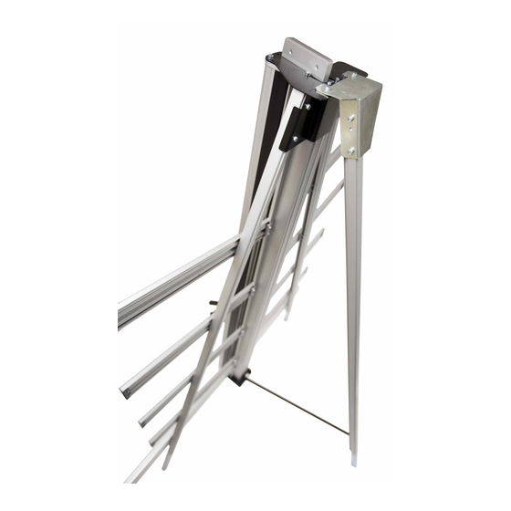
Page 9: Fitting The Optional Free Standing Kit
Assembly Fitting the optional free standing kit NOTE: The free standing kit is an optional extra and does not come packed with the main machine. ❷ ❶ ❸ Attach the bracket to the top of the machine using the nuts and screws (provided with the main machine). -
Page 10: Squaring
Squaring Checking the machine for squareness For your machine to produce accurate square cuts the main body needs to be set so that is is 90o to the squaring arm, for the following procedure you will need a piece of card or mount tboard at least 60cm x 100cm (2’... -
Page 11: Adjusting The Squareness
Squaring Adjusting the squareness ❹ Ⓑ Ⓐ Ⓐ Ⓒ NOTE: Before making any adjustments carry out the squareness check as desribed in the previous page. It is assumed that the board used for the test is still clamped in the machine. From the test results determine if the last cut made in the top of the board is to the left or right of the previous cut, as shown above: Slacken the two screws (A) joining the squaring arm to the two legs. -
Page 12: Calibration
Calibration Calibrating the verical scale ❷ ❷ ❸ Trim the bottom of the scale at zero with scissors. Remove the paper backing tape and carefully place the rule adjacent to its groove in the main body and with the zero end resting inside the material channel of the squaring arm. When aligned stick the rule in its groove. -
Page 13: Calibrating The Squaring Arm Scales
Calibration Calibrating the squaring arm scales ❶ ❷ The top edge of the squaring arm slides left to right to enable calibration. Use the 3mm hexagon wrench to loosen the screw in the back of the squaring arm if adjustment is necessary. Slide the production stop onto the outside edge of the squaring arm as shown. -
Page 14: Fitting The Sightline Strip
Fitting the sightline strip NOTE: The sightline strip is fitted to your machine but may wear or get marked with use. A spare strip is included with the machine, replacement strips are available from your distributor or Keencut. ❸ ❷ ❹... -
Page 15: Operation
Operation Using the clamp The clamping system enables the operator to control the grip pressure by means of an integral friction brake, that maintains the clamping force at the pressure applied by the operating lever. Soft materials can be held firmly without sustaining damage and solid materials are held rigidly without movement. - Page 16 Operation The multi-tool cutter head & counterbalance ❸ ❶ ❷ The Excalbur 3S is fitted with two sliding carriages running on a vertical slideway and each carriage is fitted with a cutting head. The top carriage is fitted with a twin wheel cutter for use with rigid boards such as aluminium composite panels, MDF, hardboards.
-
Page 17: Using & Changing The Cutting Blade
Operation Using & changing the cutting blade ❶ ❺ ❸ ❻ ❷ ❹ Basic cutting technique: Select the cutting blade position on the turret and clamp the material in the machine. Move the cutting head beyound the top pf the material to be cut. Press to engage the cutter. -
Page 18: Cutting Thick Material Using The Ratchet Latch
Operation Cutting thick material using the ratchet latch ❶ ❷ Ratchet latch A unique feature of the Excalibur is the ‘ratchet latch’, this enables thick dense materials such as PVC foam board to be cut easily in stages. Count the number of ‘clicks’ to position the blade just below the surface of the material to make your first cut then add an extra ‘click’... -
Page 19: Using And Changing The Scoring Blade
Rotate the turret back to the cutting position. Replace the guard ensuring it is locked closed. Replacement medium utility blades are available from Keencut or your distributor. -
Page 20: Using & Changing The Twin Wheel Cutter
Hold the twin wheel cutter and its guard to prevent them from falling and remove the screw with a 6mm hexagon wrench. Slide the cutter towards the top of the main body and lift out. Replacement wheels or cutters are available from Keencut or your distributor. -
Page 21: Maintenance
Ⓐ Cleaning Keencut machines are designed to be virtually maintenance free, however we do recommend regular cleaning. Do not wipe the squaring arm channels or remove any debris with fingers, as it may contain sharp particles such as glass. Use a vacuum cleaner if possible or if a soft brush is used, work slowly and do not allow particles to flick off the bristles.
Need help?
Do you have a question about the EXCALIBUR 3S and is the answer not in the manual?
Questions and answers