KEENCUT SteelTrak 165 Instruction Manual
165 cm - 65"
Hide thumbs
Also See for SteelTrak 165:
- Installation manual (29 pages) ,
- Installation manual (5 pages) ,
- Instruction manual (32 pages)
Table of Contents
Advertisement
Advertisement
Table of Contents

Related Manuals for KEENCUT SteelTrak 165


Summary of Contents for KEENCUT SteelTrak 165
- Page 1 T H E WORLD’S FINEST CUTTING M A C H I N E S 2 2 1 1 0 0 INSTRUCTION MANUAL Single language version and parts diagrams can be down loaded from www.keencut.co.uk MyBinding.com 5500 NE Moore Court Hillsboro, OR 97124...
-
Page 2: Table Of Contents
Contents 2 Packing list Unpacking your machine 3 Assembly Preparing the Legs Preparing to fit the Squaring arm Fitting the Squaring arm Fitting the Pull Bar (210 only) Fitting the Wall mounting bracket Fitting the Free standing kit (165 only) Fitting the Free standing kit (210 only) Fitting the Back panels Fitting the Handle... -
Page 3: Unpacking Your Machine
Unpacking your Machine 210 only Main body 12. Spare blades Squaring arm 13. Main Handle Left Back Support 14. Hexagon wrenches 2.5, 3.0, 4.0, 5.0, 6.0mm Right Back Support 15. Spare Sight-line Strip (165 – 1 off, 210 – 2 off) Long Back Support Screws 16. -
Page 4: Assembly
Assembly Preparing the Legs SteelTraK 210 only The first stages of assembly are carried out with the machine laying on the floor. NOTE: When taking the machine from the box ensure at least two people are lifting. Remember to bend your knees and keep your back straight - this machine is heavy. 1. -
Page 5: Preparing To Fit The Squaring Arm
Assembly Preparing to fit the Squaring Arm 1. Remove the following: A. One screw and spacer from each leg. B. Two sets of hexagon headed bolts, washers and nuts from the Main Body 2. Lay the Squaring Arm flat adjacent to the machine, position the two long hexagon nuts into the two large middle holes. -
Page 6: Fitting The Squaring Arm
Assembly Fitting the Squaring Arm 1. Remove the Squaring Adjuster Block from the right hand Leg by releasing the middle screw only (take note how this is fixed in place as it will replaced after the Squaring Arm has been fitted) 2. -
Page 7: Fitting The Pull Bar (210 Only)
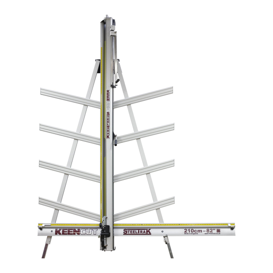
Assembly Fitting the Pull Bar (210 only) The SteelTraK 165 offers a fast, accurate and robust way to cut boards measuring up to 165cm (65”). The SteeltraK 210 utilises a ‘Pull Bar System’ to increase the cutting length to 210cm (82”) without compromising the straightforward way the SteelTraK cuts medium size boards. -
Page 8: Fitting The Wall Mounting Bracket
Assembly Fitting the Wall Mounting Bracket SteelTraK 210 only NOTE A: If you are going to fit the Free Standing Kit (optional) turn to the next page. NOTE B: Ensure the wall is stable and use the appropriate fixings. 1. Lift the top end of the machine (place it on a strong stool or chair) and fit the two M8 screws (supplied separately) through the black Top Bracket into the back of each of the Legs. -
Page 9: Fitting The Free Standing Kit (165 Only)
Assembly Fitting the Free Standing Kit (optional 165 only) NOTE: The Free standing kit is an optional extra and does not come packed with the main machine. Assistance will be needed to fit the Free Standing Kit 1. Extend the telescopic leg to the same length as the front legs less 12cm (5") 2. -
Page 10: Fitting The Free Standing Kit (210 Only)
Assembly Fitting the Free Standing Kit (optional – 210 only) NOTE: The Free standing kit is an optional extra and does not come packed with the main machine. Assistance will be needed to fit the Free Standing Kit 1. First carry out the fitting procedure (1 to 5) on the previous page. 2. - Page 11 Assembly Fitting the Back Supports 1. Tighten the two sets of nuts and bolts fixing the Squaring arm two the Main Column of the machine. 2. Tighten the two screws to clamp the Squaring Arm to the two Legs. 3. Separate the Supports into left hand and right hand. NOTE: The screws fit into special grooves in the underside of the Supports.
-
Page 12: Fitting The Handle
Assembly Fitting the Handle 1. Remove the three screws from the top of the Cutting Head and fix the Handle in place being sure it is the correct way round (as shown). Move the cutter head to the middle of the Main Body MyBinding.com 5500 NE Moore Court Hillsboro, OR 97124... -
Page 13: Squaring
Squaring Checking your machine for Squareness For your machine to produce accurate square cuts the Squaring Arm needs to be fixed at exactly 90° to the Main Column. to adjust the Squaring Arm first select a sheet of foam core or foam board (3-6mm) at least 60cm x 100cm (24” x 36”) in size. -
Page 14: Adjusting The Squareness
Squaring Adjusting the Squareness NOTE: Before making any adjustments carry out the squareness check as described on the previous page. It is assumed that the board used for the test is still clamped in the machine. From the test results determine if the last cut made in the top of the board is to the left or right of the previous cut, as shown above: 1. -
Page 15: Calibration
Calibration Calibrating the Measuring scales The vertical measuring scale is supplied separate from the machine, the two horizontal squaring arm scales are already attached to the machine but may not be positioned accurately and will need calibrating. Vertical scale: This measures the height of the board on the machine and is only used for reference. - Page 16 Calibration Calibrating the Measuring scales The two horizontal squaring arm scales are already attached to the machine but may not be positioned accurately and will need calibrating. Horizontal scales: The SteelTrak can be loaded from either side and the scales are used by eye or using the stops to measure the required width of board that will be cut off to the left or right of the cut line.
-
Page 17: Fitting The Sight-Line Strip
Calibration Fitting the Sight-line strip NOTE: The Sightline Strip is fitted to your machine but may wear or get marked with use. A spare strip is included with the machine, replacement strips are available from your distributor. The Sight-line strip is fixed to the clamp and then trimmed using the cutting blade to give an accurate guide when cutting to trim lines, the edge of an image or pencil marks. -
Page 18: Operation
Operation Using the clamp The Clamping system enables the operator to control the grip pressure by means of an integral friction brake that maintains the clamping force at the pressure applied by the operating lever. Soft materials can be held firmly without sustaining damage and solid materials held rigidly without movement. -
Page 19: The Cutting Head In General
The Multi-Cutter Head also incorporates the unique Keencut Ratchet System which gives two main advantages. Firstly, it enables thick, tough materials to be cut in multiple passes by setting the ratchet to cut through the board in stages giving the best cut quality achievable and reducing operator effort to suit the operator. -
Page 20: The Cutting Head In General
Operation The Cutting Head in General The three cutting tools are: 1. The Cutting Blade - Using a standard Medium Duty utility blade (not Heavy Duty - they will not fit) to cut PVC Foamboards like Forex®, corrugated plastic such as Correx®, card, matboard and many other types of rigid boards up to 13mm (1/2") thick. -
Page 21: How To Use The Pull Bar System
Operation How to use the Pull Bar System Cutting boards above 165cm high is done so in two stages, the first using the Pull Bar then disengaging the Pull Bar and using the handle directly connected to the Cutting Head. To cut larger than about 165cm (65”): 1. -
Page 22: The Cutting Blade
Operation The Cutting Blade Basic Cutting Technique. Select the Cutting Blade position on the turret and clamp the material in the machine. 1. Move the cutting head beyond the top of the material to be cut. 2. Press to engage the cutter. Draw the cutter down to the bottom of the machine where it will disengage automatically. -
Page 23: The Cutting Blade
Operation The Cutting Blade Ratchet Latch The unique 'Ratchet Latch', enables thick dense materials (such as PVC foam board) to be cut easily in stages. Count the number of 'clicks' to position the blade just below the surface of the material to make your first cut then add an extra 'click' for the second and subsequent cuts. -
Page 24: Changing The Cutting Blade
Operation Changing the Cutting Blade Changing the Cutting Blade Unlock and swing down the cutter guard, rotate the turret so the cutting blade is facing towards you. 3. Undo the blade clamping screw a number of turns to release the blade. 4. -
Page 25: The Scoring Blade
Operation The Scoring Blade The scoring blade is designed to score Acrylics, Plexiglass and other similar rigid plastics. Trials should be carried out on scrap materials first to ensure you obtain the required standard of cut. Scoring/Breaking Technique Select the Scoring Blade position on the turret and clamp the material in the machine. 1. -
Page 26: Glass Cutting (Optional)
Operation Glass Cutting An optional Glass Cutting Kit will be required to use this facility, operating instructions for glass cutting are not included in this manual but are supplied with the Glass Cutting Kit. MyBinding.com 5500 NE Moore Court Hillsboro, OR 97124 Toll Free: 1-800-944-4573 Local: 503-640-5920... -
Page 27: The Twin Wheel (Tw) Cutter
Operation The Twin Wheel (TW) Cutter The Twin Wheel Cutter is mounted on the upper part of the cutting head and is used for cutting a range of tough, rigid materials. The standard machine is fitted with the Composite TW Cutter and is used for cutting composite boards such as Dibond ®... -
Page 28: Changing The Twin Wheel (Tw) Cutter
Operation The Twin Wheel (TW) Cutter The cutting wheels are made from high grade tool steel and are heat treated to give give a long life but this is dependant upon daily use and the materials being cut. The signs of the wheels wearing out are: A rough finish predominately on the right hand side of the cut, with flaking on materials such as MDF. - Page 29 Maintenance Cleaning Keencut design machines to be as maintenance free as possible, however we do recommend regular cleaning. Do not wipe the squaring arm channels or remove any debris with fingers, as it may contain sharp particles such as glass. Use a vacuum cleaner if possible or if a soft brush is used, work slowly and do not allow particles to flick off of the bristles.
- Page 30 Maintenance The Clamp Adjusting the Clamping Pressure The pressure of the clamp is in relation to the amount of pressure applied to the operating handle. However in time the maximum clamping pressure can reduce due to wear on the friction block (hidden within the machine), compensation for this can be made by adjusting the two small grub screws in the housing as shown.
- Page 31 Maintenance Guide Wheel Adjustment The Cutting Head slides up and down on two stainless steel Guide Rails (1) that are embedded into the Slideway (2). There are four grooved Guide Wheels that run on the rails, the two furthest away are fixed (A) and the two closest are adjustable (B). These Guide Wheels are adjusted in the factory and should not under normal circumstances require re-adjustment.
- Page 32 Maintenance Planned Maintenance Chart Frequency: After 2 weeks of use and then every month thereafter Adjust clamp pressure (page 7.1 In the first few weeks the clamp with bed itself in and will need adjusting. See instructions on page 7.1 Check clamp alignment (page 7.1 Using 2 pieces of A4 paper, place one under the bottom end of the...
Need help?
Do you have a question about the SteelTrak 165 and is the answer not in the manual?
Questions and answers