Table of Contents
Advertisement
Quick Links
HSF Series
HSF-10
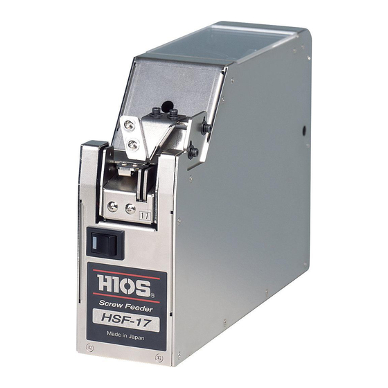
HSF-17
HSF-12
HSF-20
HSF-14
HSF-23
Instruction Manual
Read this manual before using this device.
Current as of April 2018
HIOS Inc.
1-16-5 Akiyama, Matsudo City, Chiba Pref., Japan
TEL: +81-47-392-2001 FAX: +81-47-392-7773
HSF-26
HSF-30
Automatic Screw Feeder
Manual No. ET-D002
18A
Advertisement
Table of Contents

Subscribe to Our Youtube Channel
Related Manuals for HIOS HSF-10

Summary of Contents for HIOS HSF-10
- Page 1 Automatic Screw Feeder HSF Series HSF-10 HSF-17 HSF-26 HSF-12 HSF-20 HSF-30 HSF-14 HSF-23 Instruction Manual Read this manual before using this device. Current as of April 2018 HIOS Inc. 1-16-5 Akiyama, Matsudo City, Chiba Pref., Japan Manual No. ET-D002 TEL: +81-47-392-2001 FAX: +81-47-392-7773...
-
Page 2: Table Of Contents
Contents 7. Other ......................21 1. Before using this device ............1 8. Troubleshooting ..................22 2. Precautions for use.............. 1 9. Specifications ..................25 3. Names and explanations of parts ........3 10. External Diagram ...................26 4. Making checks and adjustments before use ....... 5 11. - Page 3 Screws that must not be used Please do not use any unspecified screws or dirty or oil screws Caution when removing screws Do not use excessive force or shock when removing screws as damage or injury may result. Treatment during operation Caution Do not insert foreign objects into the device when it is operating.
-
Page 4: Names And Explanations Of Parts
3. Names and explanations of parts Screw hopper cover ① Screw hopper ② Front: rail mounting screw Center cover ④ Bit guide plate ⑤ Bit guide front/rear Adjustment screw mounting screw ⑩ Vibration frequency Bit guide plate control dial ⑪ Amplitude control dial ⑨... - Page 5 Name Explanation ① Screw hopper Insert screws to be used ② Front: rail mounting screw Used when replacing rails ③ Rear: rail mounting screw Used when replacing rails ④ Bit guide plate adjustment screw Adjust to suit screw driver bit size ⑤...
-
Page 6: Making Checks And Adjustments Before Use
4. Making checks and adjustments before use Recommended Bit Size Type Displayed Compatible Bit Tip Tip Cross Numberr Screw Size Unit 4-1 Checking model number Size M1.0 • Ensure that the screw driver bit used matches the size of the screw M1.2 Φ1.5 No. - Page 7 4-2 Basic operation The driving motor repeats normal rotation and an inversion for about 2 seconds at a time, and the scooper carries screws to the rail. The vibrator (solenoid) continuously sends screws to the front stopper to be picked up using the screwdriver. Note: If no screws are sent for approximately 10 seconds, vibration of a rail becomes stronger.
- Page 8 4-4 Check of operation • If each section has been adjusted correctly, screws will be transported to the stopper section. • Screws in the stopper section can be taken out with an electronic screw driver. The screw driver should be vertical using the bit guide as a guide. The screw driver should then be briefly rotated and moved horizontally to take the screw (Image 3). • Do not apply excessive force when moving the screw driver horizontally (when matching the bit to the screw head). Rotating the screw driver bit briefly makes it easier to line up the bit with the cross in the screw thread.
- Page 9 4-5 Adjusting the height of the brushes No adjustment is required if the brushes rotate at a height where they come in contact with the screw heads going into the rail groove when the power is switch on. • Turn the power OFF if the height of the brushes requires adjustment. • If adjustment is required, loosen the brush height adjustment screw (Image 4-1).
- Page 10 4-5-1 Adjusting the height of the passing plate/holding plate (how to remove the rail) • Adjustment of the passing plate/holding plate is required if screws become jammed at the front of the screw hopper. • Ensure that screws within the device are all removed before removing the rail (very important). • Loosen the bit guide up/down adjustment screw (Image 5). Bit guide Up/down adjustment screw Image 5 • Front/rear: loosen the rail mounting screw <do not loosen it too much> (Image 6). •...
- Page 11 4-5-2 Adjusting the height of the passing plate/holding plate • The passing plate/holding plate are mounted to the rail (Image 8). • The passing plate drops screws to be used into the passing plate section of the rail groove. Adjust the height of the passing plate mounting screw to ensure that the gap in the passing plate is sufficient. Screws can become easily jammed if this gap is too large. If there is no gap, the screws cannot pass through. The ideal gap is one that allows the screws to just pass through.
- Page 12 • The holding plate drops screws to be used into the rail groove directly below the holding plate. Adjust the height of the holding plate mounting screw to ensure that the gap is sufficient. (Image 10) <Remove the holding plate and drop a screw into the groove to allow easy adjustment> (Image 11) Screws may be thrown out if this gap is too large. If there is no gap, the screws cannot move. The ideal gap size is between 0.2 and 0.5mm.
- Page 13 4-6 Checking and adjusting rail oscillations • The factory setting for oscillation suits ordinary purpose screw thread sizes that can be used with the supplied rail. (Check the rail thread size on the label at the front of the rail. Eg: 17 means a M1.7 thread) • Place 2 or 3 screws to be used into the rail groove and turn the power on.
- Page 14 4-7 Checking and adjusting the bit guide • Check and adjust the position of the bit guide. • Make adjustments while repeatedly taking screws out. • When making adjustments, loosen the various adjustment screws. Bit guide Front/rear mounting Bit guide Plate • Refer to image 14 for the location of various adjustment screws. screw Bit guide Up/down adjustment screw Image 14 Plate adjustment screw Adjusting the bit guide • The height of the bit guide can be adjusted with the bit guide height adjustment screws.
- Page 15 4-8 Checking and adjusting the timer This device includes a sensor to detect a rail full with aligned screws. If a screw accumulates to some extent on a rail, operation of a scooping block will stop and vibration will stop after time set time. The timer is usually set to MIN.
- Page 16 4-9 Checking and adjusting the sensor voltage level The sensor level in the device can be used with the majority of screws with its default settings. However, differences in screw head height and shape, or if the rail has been replaced, mean that the device may not operate correctly, therefore requiring Expanded view further adjustment.
- Page 17 Adjusting the screw feed sensor <using pin number 5> This sensor detects movement of the stopper. Loosen the stopper sensor bracket mounting screws (2 places) and adjust the Stopper sensor Bracket Mounting screws light receptor in a sideways direction. (Image 19) Stopper The sensor level is adjusted so that it is 4V or greater with the stopper in the ON position, and 0.2V or less with the stopper in the OFF position.
-
Page 18: Maintenance
5. Maintenance The transport speed of screws to be used may become slower if the rail groove becomes dirty. If the rail is extremely dirty, use a thin cloth soaked in alcohol to clean the rail groove. The rail can be removed from the device if you find it difficult to clean the rail. - Page 19 (This positions the brush mounting screws in an easy to reach location) • The brush tip mountings are as shown on the right. • Assemble the brushes in the reverse order of disassembly. • For adjustments, refer to “Making checks and adjustments before use”. Brush part numbers Image 21 HSF-02107: HSF-10, HSF-12, HSF-14, HSF-17, HSF-20 HSF-22001-23: HSF-26, HSF-30 Hexagonal socket screw M2.6 x 10 Spring washer M2.6 Plain washer M2.6...
- Page 20 6-2 Replacement and adjustment of the drive belt If misaligned screws are no longer swept up by the tips of the brushes due to slipping of the brushes or faulty brush rotation from a worn drive belt, the belt should be replaced with a new item. • Turn the power switch ON/OFF and remove the left and center covers.
- Page 21 6-3 Replacing the main motor The driving Cam Assy should be replaced with a new one if it becomes damaged. • Remove the rail and the front, center, and left and right covers. Loosen the 2 clips that hold the wiring in place. • Remove the motor mounting screws (4 places) on the base of the device, and slide out the motor unit from the left side of the device (Image 24). Loosen the clips. Image 24 Loosen clip Motor mounting screw (4 places) Pull slightly to the back and slide out to the left. Driving Cam Assy Insert a roller into "C"...
-
Page 22: Other
7. Other Overload protection circuits This device includes overload protection circuits. Under ordinary operation, the drive motor rotates correctly (ordinary rotation), transporting screws to the rail section, enabling screws to be taken out continuously. However if the drive sections become overloaded, the drive motor rotates in the reverse direction briefly, followed by correct rotation. -
Page 23: Troubleshooting
8. Troubleshooting Caution Turn OFF the power switch before diagnosing any symptoms. Symptoms Cause Solution • Check the power connection to the AC adapter • There is no power being supplied to the device The device does • Remove the screw at the screw feeding point • A screw at the screw feeding point has not been not operate even •... - Page 24 Symptoms Cause Solution • Use screws with specified threads • Screws smaller than the rail specified thread have A screw has fallen been inserted • Screws longer than the rail groove width have been into the rail groove • Incompatible Seek advice separately inserted • The gap between the holding plate and screws is • Adjust the holding plate too small Poor movement of • Adjust the oscillation • Screws with spring washers that are one step small- screws within the er than the rail specified thread have been inserted...
- Page 25 Symptoms Cause Solution • Turn the power switch back on • The overload protection circuit has been tripped • Remove the cause of the overload The device stops operating suddenly • Insert the appropriate amount of screws • Too many screws in the panning area • Contact the store of purchase if the device stops with the appropriate amount of screws •...
-
Page 26: Specifications
(mm) head washer Mode (∅) (∅) (∅) (mm) face HSF-10 M1.0 0.9 - 0.95 1.2 - 2.0 0.35 - 1.0 1.6 - 10 HSF-12 M1.2 1.1- 1.15 1.4 - 2.3 0.35 - 1.0 1.8 - 10 -... -
Page 27: External Diagram
10. External Diagram 19.7 (Pick-up position) 16.4 10.2 - 26 -... -
Page 28: The Following Table Is For China Rohs2
THE FOLLOWING TABLE IS FOR CHINA RoHS2. f you are asked by China Customs, please show this table to them. 有害物质名称及含量标识格式 产品中有害物质的名称及含量 有害物質 部件名称 六价铬 多溴联苯 多溴二苯醚 汞 (Hg) 铅 (pb) 镉 (Cd) (CR(VI)) (PBB) (PBDE) 驱动齿轮, × ○ ○ ○...
Need help?
Do you have a question about the HSF-10 and is the answer not in the manual?
Questions and answers