
Related Manuals for McQuay Suite Incremental


Summary of Contents for McQuay Suite Incremental
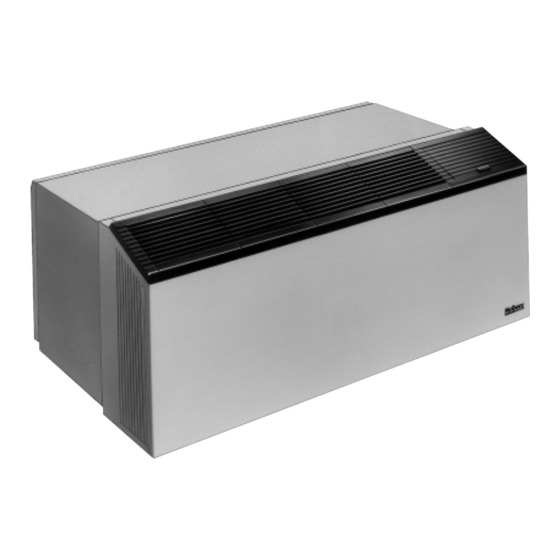
- Page 1 Installation & Maintenance Data IM 368-7 Group: PTAC Part No.: 106018472 Date: November 2003 ™ ® Suite Incremental PTAC/PTHP Conditioner ® ©2003 McQuay International...
-
Page 2: Table Of Contents
Each conditioner consists of the following components: 1. Heating/Cooling Chassis — Shipped separate. edging the damage. The carrier should also fill out a Carrier Inspection Report. The McQuay International Traffic 2. Cabinet/Wall Sleeve — Shipped separate. Department should then be contacted. -
Page 3: Nomenclature
C = 208 - 60 - 1 015 = 15,000 J = 265 - 60 - 1 McQuay PTAC/PTHP Product Identifiers DEA = Suite II, 2 motor, automatic damper SEA = A/C w/Electric Heat & Automatic OA Damper DEC = A/C & Elec/Hyd Htg Chassis w/Corr. Protection SEC = A/C w/Electric Heat &... -
Page 4: Wall Sleeve Installation Frame & Brick
Wall Sleeve Installation — Frame and Brick A heavy-gauge, corrosion resistant cabinet/wall sleeve is provided for each unit. The cabinet/wall sleeve is either shipped in a separate carton, shipped in a multi-pack of 15 or in a single carton with the heating/cooling chassis. Figure 3. -
Page 5: Panel Wall Construction
Wall Sleeve Installation — Panel Wall Construction For panel wall and thin wall construction, it is recommended that a louver frame be used. Refer to page 7 for installaton of louver frame before continuing. Panel wall and thin wall construction varies only slightly from frame Figure 6. -
Page 6: Thick Wall Construction
Wall Sleeve Installation — Thick Wall Construction Installation of cabinet/wall sleeves for thick walls requires special Table 1. Maximum Wall Thickness without Sleeve Extensions consideration. Table 1 should be used to determine the maximum wall thickness allowed for the standard cabinet/wall sleeve. -
Page 7: Wall Sleeve Extension
Wall Sleeve Extensions The standard cabinet/wall sleeve will accommodate a maximum Figure A. Wall Sleeve Extension wall thickness described in Table 1. For thicker walls, cabinet/wall sleeve extensions are available from your local representative. When it is supplied by the representative, it is treated for maximum corrosion resistance and matched to the exact size of the standard wall sleeve. -
Page 8: Subbase Installation
Subbase Installation Electric Subbase An electrical subbase is optional for all 208V and 230V units. A proper score line. Insert the extension pieces into the front subbase is standard for all 265V units. The standard subbase is assembly and secure with two short black screws at available with 3"... -
Page 9: Installation Of Optional Condensate Drain Kit
Installation of Optional Condensate Drain Kit Note: Heat pump models will generate condensate during 2. Drill a " (13mm) diameter hole in the base of the cabinet/ the heating season. To insure that no condensate will run wall sleeve for the drain line. down the building, always use a drain kit with the heat pump. -
Page 10: Installation Of Louvers
Installation of Louvers 1. Remove louver and mounting hardware from the shipping 4. Push the louver through the opening at the rear of the wall carton. box, then pull the louver back to the wall sleeve flange so that 2. Remove temporary cardboard weather panel from cabinet/ the louver studs pass through the holes in the flange. -
Page 11: Adjusting Temperature Limiting Device
30°F its equipment. After the equipment leaves the McQuay factory, it (-1°C) to 35°F (1.6°C). Outdoor fan should be on whenever may become damaged or maladjusted during transportation or compressor operates. -
Page 12: Remote Mounted Thermostat
5 VA. If more than one slave unit is used, the master transformer must be replaced with a larger one. The B. McQuay recommends that every year the chassis be removed number of slave units that can be connected is limited to the for a thorough checkup. -
Page 13: Recommended Spare Parts
Touch-up Paint (1 pt. spray can) ......replenished. To the right is listed the kinds of parts which McQuay... -
Page 14: Troubleshooting Chart
High voltage due to fluctuations in local power system; usually occurs at low load periods of the day. c. If confirmed, ship cooling chassis prepaid to nearest McQuay c. Partial short circuit in compressor motor. Under normal loading a compressor with a partial short circuit might authorized warranty station. -
Page 15: Approximate Shipping Weights
TROUBLE CAUSE CURE 8. Insufficient cooling g. Restricted capillary tube or strainer, indicated by: g. *Ship prepaid to nearest McQuay warranty station. capacity (continued). 1) Frost on capillary or strainer. 2) Low wattage. 3) Condenser not warm. 4) Evaporator partially frosted, only partially cool or not at all. - Page 16 IM 368 / Page 16 of 20 (Rev 11/03)
- Page 17 IM 368 / Page 17 of 20 (Rev. 11/03)
-
Page 18: Wiring Diagrams
IM 368 / Page 18 of 20 (Rev 11/03) - Page 19 IM 368 / Page 19 of 20 (Rev. 11/03)
- Page 20 ® © 2003 McQuay International • www.mcquay.com • 800-432-1342 Page 20 of 20 / IM 368-7 / (Rev 11/03)
Need help?
Do you have a question about the Suite Incremental and is the answer not in the manual?
Questions and answers