
Related Manuals for McQuay SWT C Series


Summary of Contents for McQuay SWT C Series
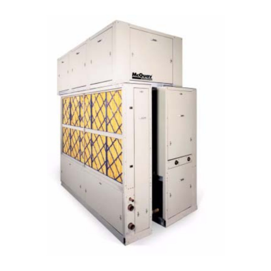
- Page 1 Installation and Maintenance IM-709 Group: Applied Systems Part Number: IM709 Date: January 2002 Self-contained Air Conditioning System Type SWT “C” Vintage Sizes 18 thru 40 368-93-E © 2002 McQuay International...
-
Page 2: Table Of Contents
High Pressure Switches ....... . 30 Copyright © 2002 McQuay International. All rights reserved throughout the world. -
Page 3: Introduction
Introduction General Description field wiring options and requirements, and service proce- dures, refer to Bulletin No. IM 710, “MicroTech II Self-con- Models SWTO18C through 040C are factory assembled, tained Unit Controller’ For a description of operation and refrigerant charged and tested, water cooled packaged air information on using and programming the MicroTech II conditioning units designed for ducted applications. -
Page 4: Installation
Installation Note: Installation and maintenance must be performed For units provided with more than (8) isolator pads, evenly space the additional pads under the front and rear base chan- only by qualified personnel who are familiar with nels. local codes and regulations, trained and experi- enced with this type of equipment. -
Page 5: Disassembly Of Sections
Disassembly of Sections Main cooling/heating — filter/waterside economizer sections disassembly If units are ordered for modular construction, they may be easily disassembled into three sections. The figures below The following information is for units ordered for modular illustrate the main cooling/heating, filter/waterside econo- construction (code 32=1). -
Page 6: Field Mounting Of Sensors
Field Mounting of Sensors loose in the main cooling/ heating section. The four items are located on the right side of the section when facing the front of the unit. A hole is provided leaving the main cooling/heat- Units with fan section shipped separate ing section entering the filter/waterside economizer section. -
Page 7: Refrigerant Piping
Refrigerant Piping Pressure Relief Valves All units have individual condensers per refrigerant circuit CAUTION and each condenser is provided with a spring loaded relief valve. The valve is set to open when refrigerant pressure When refrigerant is vented to the outside of the reaches 400 psig. -
Page 8: Water Connections
Water Connections General to 10°F before entering the condenser, allowing suitable condenser water temperatures whenever the tower sup- Due to the variety of piping practices, follow the recommen- ply temperature is 50°F or higher. Without head pres- dations of local authorities. They can supply the installer sure control, mechanical cooling is locked out below with the proper building and safety codes required for code- 55°F EWT. - Page 9 Figure 5. Condenser water pressure drop Figure 7. Waterside economizer pressure drop SWT018C-028C SWT018C-040C (60) 20 (210) 70 (180) 60 (150) 50 (45) 15 (120) 40 (90) 30 (30) 10 (27) 9 (60) 20 (24) 8 (45) 15 (21) 7 (18) 6 (30) 10 (27) 9...
-
Page 10: Condensate Drain Connection
Figure 9. Water regulating valve pressure drop Condensate Drain Connection Head pressure control The condensate drain connection is 11/8" O.D.S. copper and (120) 40 is located on the same end of the unit as the condenser water (105) 35 connections. The drain is internally trapped at the factory (90) 30 requiring no external trap. -
Page 11: Duct Connections
Duct Connections Supply Air Figure 10. Two-fan unit top detail For connection of supply ductwork directly to the unit, a duct collar must first be mounted at the fan outlet, avoiding the mounting screws located around the perimeter of the fan discharge opening. -
Page 12: Return Air
Return Air Note: Do not obstruct unit access panel located below the return opening. Air return to the unit can be arranged in different ways. Note: For units with ducted return, connect the open port on the clogged filter switch (PC5) to the return air 1. -
Page 13: Physical Data
Physical Data Table 2. SWT018C-040C English units Table 2a. SWT018C-040C SI units DATA SWT MODEL SIZE DATA SWT MODEL SIZE 018C 023C 028C 035C 040C 018C 023C 028C 035C 040C COMPRESSOR COMPRESSOR Quantity 2, 3, 4 3, 4 Quantity 2, 3, 4 3, 4 Size (see application chart, Table 4) - Page 14 Table 3. Compressor circuit charge Table 4. Compressor application chart COMPRESSOR HORSEPOWER MIN. COMPRESSOR *REFRIGERANT OIL CHARGE MODEL CKT#1 CKT#2 CKT#3 CKT#4 (HP) CHARGE PER PER CIRCUIT SIZE (L/s) (L/s) CIRCUIT (R-22) (OZ.) 24 (1.5) 42 (2.7) 018C 36 (2.3) 62 (4.0) 9 Ibs.
-
Page 15: Dimensional Data
Dimensional Data Figure 13. Left Side Front (CW) Discharge Figure 14. Left Side Back (CCW) Discharge Note: (1) Select unit arrangement on the unit selection. (2) There are two victaulic connections for condenser water at module split. Table 5. BASIC UNIT 018C 023C 028C... - Page 16 Figure 15. Unit Front Plan and Front Elevation Return Air Left side piping Right side piping connections connections (optional) Supply fan motor Unit Front Plan 15.0 (381) 6.46 (164) Outlets 34.0 (864) Connection Plate MicroTech II Power entry System 7/8" (2.2) KO Indicator Panel Electrical...
- Page 17 Figure 16. Back Elevation and Left Side Notes: 6. Filters are removable from the rear of the unit or through a 9. There are two access doors on 018C, 023C and 028C side filter access door, located on the piping connection side. instead of three as shown.
-
Page 18: Unit Weights
Unit Weights Table 6a. Unit and Component Weight Table 6b. Unit and Component Weight English Units in lbs. SI Units in kg. UNIT SIZE UNIT SIZE COMPONENT COMPONENT 018C 023C 028C 035C 040C 018C 023C 028C 035C 040C MAIN COOLING/HEATING SECTION MAIN COOLING/HEATING SECTION Main Base 1045... -
Page 19: Field Wiring
Field Wiring General Return Air and Outside Air Sensors Wiring must comply with all applicable codes and ordi- All units are provided with a return air sensor. The outside nances. The warranty does not cover equipment failures air sensor is optional and can be ordered with the unit. The caused by or contributed to wiring not in accordance with return air sensor is connected to the input control board and specifications. -
Page 20: Supply Power Wiring
Table 9 Supply Fan Motor Data 208/60/3 230/60/3 460/60/3 575/60/3 400/50/3 Horsepower TYPE High Efficiency Premium Efficiency High Efficiency 14.8 14.0 Premium Efficiency 15.7 13.6 High Efficiency 22.3 21.6 10.8 10.8 Premium Efficiency 22.3 20.0 10.0 10.0 High Efficiency 29.7 28.0 14.0 14.0... -
Page 21: Control Center
Control Center All electrical controls are enclosed in a central control center If the optional disconnect switch is provided, the switch han- located at the front of the unit. The control center is divided dle is visible and accessible without removing any safety or into two separate compartments, high and low voltage. -
Page 22: Electrical Legend
Electrical Legend Designation Description Standard Location Designation Description Standard Location ACT1 ACTUATOR,VARIABLE INLET VANES SUPPLY FAN SECTION OUTSIDE AIR ENTHALPY EXTERNAL ACT2 ACTUATOR,BYPASS VALVE CONDENSER VALVE OUTSIDE AIR TEMP. SENSOR EXTERNAL ACT3 ACTUATOR,WATERSIDE ECONOMIZER WATERSIDE ECONO OL10 OVERLOAD RELAY--SUPPLY FAN MAIN CONTROL VALVE AFD10... -
Page 23: Typical Wiring Schematics
Typical Wiring Schematics Figure 19. Power Schematic IM709... - Page 24 Figure 20. Input Schematic, Discharge Air Control (DAC) IM709...
- Page 25 Figure 21. Input Schematic, Zone or Space Comfort Control (SCC) IM709...
- Page 26 Figure 22. Output Schematic, Actuator Control IM709...
- Page 27 Figure 23. Output Schematic, Auxiliary Fan Start/Stop Control IM709...
- Page 28 Figure 24. Output Schematic, Actuator Control IM709...
-
Page 29: (4 Compressors /4, 5 Or 6 Stage)
Figure 25. Output Schematic, Compressor Control (4 Compressors /4, 5 or 6 Stage) IM709... -
Page 30: Standard Controls
Standard Controls High Pressure Switches Proof of Airflow Switch The high pressure switch (HP1-HP4) is a single pole pres- A positive proof of airflow switch (PC7) is provided with all sure activated device that opens on a pressure rise. When the units. -
Page 31: Unit Options
Unit Options Duct High Limit The sensing tube should be located in a non-turbulent flow area of the duct. Keep several duct widths away A duct high limit (DHL) pressure control is provided as stan- from take-off points, bends or neck downs. dard with all units having variable air volume control. -
Page 32: Building Pressurization Applications
Condenser Water Flow Switch A pressure differential type flow switch (WF1) is available CAUTION to verify flow to the unit condensers before compressor oper- ation is allowed. The flow switch is factory installed in the Fragile sensor fittings. Excess force can dam- unit next to the condenser piping connections. -
Page 33: Variable Inlet Vanes
Variable Inlet Vanes Disconnect Switch An optional variable inlet vane assembly is available for A factory mounted, nonfused main circuit interrupter for dis- variable air volume applications. The assembly consists of connecting the main electrical power is available. The switch inlet funnels with integral sets of lever-actuated radial vanes, is located at the front of the unit on the control panel and is one assembly for each side of the fan. -
Page 34: System Check, Test And Start
(supplied with each unit) must be COUPLING GAGE PORT STEM CAP COUPLING NUT SIZE CAP TORQUE TORQUE NUT TORQUE signed and returned to McQuay International. INCH LBS-FT LBS-FT LBS-FT Note: Always open power disconnect switch before open- 1.00 7±1 32±2... -
Page 35: Fan Start-Up
Fan start-up If the compressor motor hums but does not run, verify that the unit is getting three phase power. Place the unit into the "FAN ONLY" mode through the The compressors should run continuously. If a compressor keypad: cycles on the low pressure switch: System summary Verify that the circuit is not low on charge. -
Page 36: Refrigerant Charge
Refrigerant Charge Figure 26. Water and Refrigerant Piping Schematic Units are shipped with a full operating charge of refrigerant SIGHT ISOLATION RELIEF FILTER ISOLATION VALVE GLASS DRIER VALVE and oil. However, in the event of a leak in the system, some VALVE RECEIVER added charge may be required. -
Page 37: Variable Air Volume (Vav) Start-Up
Variable air volume (VAV) start-up Heating/Cooling control parameters set as required. Alarm limits set as required. Enter the duct static pressure setpoint value and parameters through the keyboard: Night setback parameters set as required. Air/Water Flow Duct static pressure, building static pressure, as Duct static pressure required. -
Page 38: System Maintenance
System Maintenance chemically or mechanically. Tubing should be kept clean to maintain system performance. WARNING Lubricate motor and fan shaft bearings. Align or replace belts as needed. Installation and maintenance must be per- Replace filters as needed. formed only by qualified personnel familiar Check refrigerant sightglass. -
Page 39: Replacement Parts
Replacement Parts Description McQuay Part Number Zone temperature sensor with tenant override 111048101 Outside air temperature sensor 060004703 Airflow proving switch 060015801 Discharge air temperature sensor 060004702 Return air temperature sensor 060004703 Freeze stat 072502001 Filters Part Number Unit Size Filter Size 2"-35%... -
Page 40: Service And Warranty Procedure
Abuse, misuse, or alteration Replacement Parts of the product in any manner voids the Company's warranty When writing to McQuay for service or replacement parts, obligation. Neither the parts or extended warranty obligates refer to the model number, serial number, and G.O. number the Company to pay any labor or service costs for removing of the unit as stamped on the serial plate attached to the unit. -
Page 41: System Check, Test And Start Form
System Check, Test and Start Form Compressorized Equipment Warranty Registration Form: This form must be filled out and returned to McQuay, Warranty Department, within 10 days in order to comply with the terms of McQuay Warranty. Check, Test and Start Procedure for SWP/SWT (Self-contained Air Conditioning Systems) Job Name: McQuay G.O. - Page 42 START-UP Does the unit start & perform per sequence of operation as stated in IM Bulletin? Does the fan rotate in the right direction? Condenser inlet water temperature Deg. F _____ Condenser outlet water temperature Deg. F. _____ Number of Compressors Operating Deg.
- Page 43 Are VAV boxes set to keep a minimum airflow of 40% of design? Do the Economizer, Water Regulating, and Hot Water valves rotate freely? Performed By: Title: Signature: Date of Start-up: RETURN COMPLETED FORM TO: McQuay International Warranty Department 13600 Industrial Park Boulevard Minneapolis, MN 55441 Comments: IM709...
- Page 44 13600 Industrial Park Boulevard, Minneapolis, MN 55441 USA (763) 553-5330...
Need help?
Do you have a question about the SWT C Series and is the answer not in the manual?
Questions and answers