
Related Manuals for McQuay Incremental PDNS Series


Summary of Contents for McQuay Incremental PDNS Series
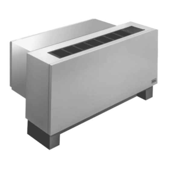
- Page 1 Installation & Maintenance Data IM 422-6 Group: PTAC Part No.: 106018563 Date: August 2005 ® Incremental Comfort Conditioners Model PDNS, PDNC With Top-Mounted Hydronic Heat ® ©2005 McQuay International...
-
Page 2: Table Of Contents
1. Cooling Chassis — Shipped separate in a single carton. 2. Wall Sleeve — Shipped separate in a single carton or in a edging the damage. The carrier should also fill out a Carrier Inspection Report. The McQuay International Traffic Department multi-pack of 15. should then be notified. -
Page 3: Nomenclature
Product Nomenclature Product Category Product Style P = PTAC 1 = 1st Style Change Product Identifier SKU Type DNS = A/C w/Top-Mnt Hyd Heat A = Stock (Flat Top) B = Quick Ship DNC = A/C w/Top-Mnt Hyd Heat & C = Tailored Corrosion Protection Color... -
Page 4: Panel Wall With Factory Louver
Wall Sleeve Installation — Thin Wall Construction Figure 3. Wall sleeve installation for thin wall construction The standard wall sleeve is designed to be easily installed in a variety of wall constructions. For panel wall and thin wall construction, it is recommended that the optional top angle be used and the wall sleeve be supplied with a turned down flange (see Figure 3). -
Page 5: Panel Wall With Continuous Louver
1 ⁄ " (29mm) beyond the finished wall surface. This is to accommodate the heat 2. McQuay does not warrant the rain and water leakage section and room cabinet. The center of gravity is 10 ⁄ "... -
Page 6: Wall Sleeve Installation
Wall Sleeve Installation — Thick Wall Construction A heavy-gauge, corrosion resistant wall sleeve is provided 4. If a brickstop is employed (as shown in Figure 5), slide the for each unit. The wall sleeve is either shipped in a separate wall sleeve into the wall until the brickstop contacts the carton or shipped in a multi-pack of 15. -
Page 7: Heat Section Installation
Heat Section Installation Supply and Return Coil Arrangements Steam Left-hand supply and return The heat section is designed to be “snapped” into the top of the wall sleeve (see Figure 6). There are four square holes pro- vided in the wall sleeve, two on each side, for coil attachment. Assembly the heat section to the wall sleeve as follows: Supply 1. -
Page 8: Wall Mounted Thermostats
Wall Mounted Thermostats Figure 15. 7-Day Programmable, Manual Changeover Wall mounted thermostats are available for the PDNS/PDNC Thermostat (107095801) unit in automatic or manual changeover styles. All include a fan switch for constant “on” operation or “automatic” for cycle op- eration with the compressor. - Page 9 Thermostat Dimensions – 107095701, Specifications 107095801, 107095901 Electrical Rating: • 24 VAC (18 to 30 VAC) • 1 amp maximum per terminal • 4 amp maximum total load • 60-minute power backup for clock Temperature Control Ranges: F, Accuracy: ±1 •...
-
Page 10: Wireless Remote (Option)
Wireless Remote Control (Optional) Mode Buttons • Heat, Cool, Cool/Dry, Fan: Performs same function as the MODE button on the touch pad, and allows user to select specific mode of operation using only one button. • Temp Buttons – : Functions same as buttons on touch pad, allowing user to change the setpoint. - Page 11 Programmable Thermostat Master/slave Operation With Programmable Thermostat – The major difference in connecting the programmable thermostat is the requirement for – Master/slave operation can also be controlled by a program- the transformer common, the introduction of the thermostats mable thermostat. However, the connection of the master unit is power source.
-
Page 12: Anchoring
Anchoring Anchoring the wall sleeve in the opening is accomplished as Figure 23. Anchoring Method shown in Figure 23. It is recommended that rubber isolation washers be used with the fasteners to minimize sound transmission from the equipment to the wall, at the point of con- tact. -
Page 13: Adjusting Temperature Limiting Device
Optional Adjusting Temperature Limiting Device As an option, a temperature limiting device can be furnished to 4. Tighten hold-down screw. allow the owner to set the minimum and/or maximum tempera- 5. Replace metal cover and temperature knob. ture selections. Adjust this device as follows: Once unit is in operation, rotate knob to maximum heat 1. -
Page 14: Equipment Start-Up
Unit malfunction may occur if air filters are not kept clean. k. Clean insulation or replace if necessary. 2. McQuay recommends that every year the chassis be re- l. Check all fasteners and tighten as required. moved for a thorough checkup. This should be m. -
Page 15: Recommended Spare Parts
Damper Motor (if used) ......2 then be returned to McQuay or one of its authorized service Touch-up Paint (1 pt. -
Page 16: Troubleshooting Chart
Consult local power company. usually occurs at low load periods of the day. Partial short circuit in compressor motor. Under normal If confirmed, ship cooling chassis prepaid to nearest McQuay loading a compressor with a partial short circuit might authorized warranty station. -
Page 17: Approximate Shipping Weights
2) Condenser not warm, evaporator only partially cool or not at all. g. Restricted capillary tube or strainer, indicated by: g. 4) *Ship prepaid to nearest McQuay warranty station. 1) Frost on capillary or strainer. 2) Low wattage. 3) Condenser not warm. -
Page 18: Wiring Diagrams
IM 422 / Page 18 of 28... -
Page 19: Normally Open Valve (Hot Water)
IM 422 / Page 19 of 28... -
Page 20: Digital Touch-Pad Control Wiring
PDNS/PDNC Wiring Diagram Unit Mounted Digital Touch Pad Control - First Release IM 422 / Page 20 of 28... -
Page 21: Pdns/Pdnc Control Remote Thermostat (N.o. Valve - 24V)
IM 422 / Page 21 of 28... -
Page 22: Pdns/Pdnc Control Unit Mounted (N.o. Valve - 24V)
Wiring Diagram — PDNS/PDNC Control Unit Mounted (N.O. Valve - 24V) IM 422 / Page 22 of 28... -
Page 23: Need Heading Description
IM 422 / Page 23 of 28... -
Page 24: Pdns/Pdnc Control Remote Thermostat (N.c. Valve - 24V)
IM 422 / Page 24 of 28... - Page 25 IM 422 / Page 25 of 28...
-
Page 26: Pdns/Pdnc Control Unit Mounted With Hflo Fan Cycle On Heat (N.c. Valve - 24V)
Wiring Diagram – PDNS/PDNC Control Unit Mounted with HFLO Fan Cycle on Heat (N.C. Valve - 24V) IM 422 / Page 26 of 28... -
Page 27: (Manual Changeover N.c. Valve)
Wiring Diagram — PDNS/PDNC Unit Mounted Thermostat (Manual Changeover N.C. Valve) IM 422 / Page 27 of 28... - Page 28 This document contains the most current product information as of this printing. For the most up-to-date product information, please go to www.mcquay.com. ® ©2005 McQuay International • www.mcquay.com • 800-432-1342 IM 422-6 / Page 28 of 28 (Rev 8-05)
Need help?
Do you have a question about the Incremental PDNS Series and is the answer not in the manual?
Questions and answers