
Related Manuals for Queclink GV55


Summary of Contents for Queclink GV55
- Page 1 GV55LITE User manual GV55 GPS Locator User Manual TRACGV55LITEUM001 Revision: 1.01 h ttp://www.queclink.com s ales@queclink.com TRACGV3SUM001 - 1 -...
- Page 2 All specification supplied herein are subject to change without notice at any time. GV55 has been tested and found to comply with the limits for a Class B digital device, pursuant to part 15 of the FCC Rules.
-
Page 3: Table Of Contents
2 Product Overview ..........................8 2.1. Check Part List ........................8 2.2. Parts List..........................9 2.3. Interface Definition ......................9 2.4. GV55 User Cable Colour ....................10 3 .Getting Started ..........................11 3.1. Opening the Case ......................11 3.2. Closing the Case........................ 11 3.3. Installing a SIM Card ......................12 3.4. - Page 4 TERMS AND ABBREVIATIONS ..................7 TABLE 3. PART LIST ........................9 TABLE 4. DESCRIPTION OF 6 PIN CONNECTIONS..............9 TABLE 5. GV55 USER CABLE COLOUR DEFINITION ............10 TABLE 6. ELECTRICAL CHARACTERISTICS OF IGNITION DETECTION ......13 TABLE 7. ELECTRICAL CHARACTERISTICS OF THE DIGITAL INPUTS ......13 TABLE 8.
- Page 5 GV55 User manual Figure Index FIGURE 1. APPEARANCE OF GV55 ....................8 FIGURE 2. THE 6 PIN CONNECTOR ON THE GV55..............9 FIGURE 3. OPENING THE CASE....................11 FIGURE 4. CLOSING THE CASE....................11 FIGURE 5. SIM CARD INSTALLATION..................12 FIGURE 6. TYPICAL POWER CONNECTION................12 FIGURE 7.
- Page 6 GV55 User manual Revision History Revision Date Author Description of change 1.01 2012-7-31 Owen Feng Initial TRACGV55LITEUM001 - 6 -...
-
Page 7: Introduction
GV55 User manual 1 Introduction The GV55 is a powerful GPS locator designed for vehicle or asset tracking. It has superior receiver sensitivity, fast TTFF (Time to First Fix) and supports Dual-Band GSM frequencies 850/900/1800/1900, its location can be monitored in real time or be periodically tracked by a backend server or other specified terminals. -
Page 8: Product Overview
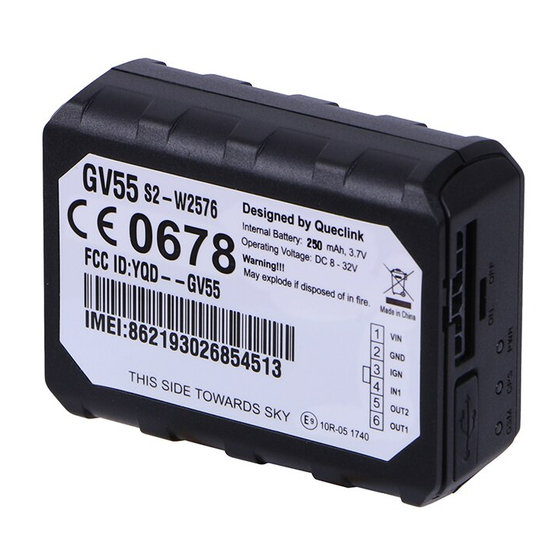
GV55 User manual 2 Product Overview 2.1. Check Part List Before starting, check all the following items have been included with your GV55. If anything is missing, please contact your supplier. Figure 1. Appearance of GV55 TRACGV55LITEUM001 - 8 -... -
Page 9: Parts List
63mm*50mm*13.2mm User Cable 2.3. Interface Definition The GV55 has a 6 PIN interface connector. It contains the connections for power, I/O. The sequence and definition of the 6PIN connector are shown in following figure: Figure 2. The 6 PIN connector on the GV55 Table 4. -
Page 10: Gv55 User Cable Colour
GV55 User manual 2.4. GV55 User Cable Colour Table 5. GV55 User Cable Colour definition Definition Color Cable Black White Orange OUT2 Green OUT1 Blue TRACGV55LITEUM001 - 10 -... -
Page 11: Getting Started
GV55 User manual 3 .Getting Started 3.1. Opening the Case Figure 3. Opening the Case Insert the triangular-pry-opener into the gap of the case as shown below, push the opener up until the case unsnapped. 3.2. Closing the Case Figure 4. -
Page 12: Installing A Sim Card
GV55 User manual Place the cover on the bottom in the position as shown in the following figure. Slide the cover against the direction of the arrow until it snapped. 3.3. Installing a SIM Card Open the case and ensure the unit is not powered (unplug the 6Pin cable). Slide the holder right to open the SIM card. -
Page 13: Ignition Detection
IGN signal can be configured to start transmitting information to back-end server when ignition is on; and enter power saving mode when ignition is off. 3.6. Digital Inputs There are one general purpose digital inputs on GV55. They are all negative trigger. Table 7. Electrical Characteristics of the digital inputs Logical State... -
Page 14: Digital Outputs
Typical Digital Input Connection 3.7. Digital Outputs There are two digital outputs on GV55. All are of open drain type and the maximum drain current is 150mA. Each output has the built-in over current and recovery PTC fuse Figure 9. -
Page 15: Device Status Led
GV55 User manual Figure 10. Typical Connection with Relay Figure 11. Typical Connection with LED Note: 1 - OUT1 will latch the output state during reset. 2- All outputs are internally without pulled up to PWR pin by a diode. So an external flyback diode is needed when the output is connected to an inductive load. -
Page 16: Table 9. Definition Of Device Status And Led
GV55 User manual Figure 12. GV55 LED on the Case GV55 has three status led that GSM GPS PWR led. Table 9. Definition of Device status and LED TRACGV55LITEUM001 - 16 -... - Page 17 GV55 User manual Note: Device status LED status Device is searching GSM network Fast flashing (note1) (Note3) Device has registered to GSM network. Slow flashing (Note4) SIM card needs pin code to unlock. GPS chip is powered off (note 2) GPS sends no data or data format error.
Need help?
Do you have a question about the GV55 and is the answer not in the manual?
Questions and answers