
Subscribe to Our Youtube Channel
Related Manuals for CAME 001DC011AC


Summary of Contents for CAME 001DC011AC
- Page 1 AUDIO ENTRY KIT FA00959-EN 001DC002AC 001DC02EARY – – 001DC011AC 001CS1PLCO 001DC011AC INSTALLATION MANUAL 001CK0009 001CK0012 FR-001CK0013 FR EN English...
-
Page 2: Installation
General Notes • Read the instructions carefully before beginning the installation and carry out the actions as specified by the manufacturer. • The installation, programming, commissioning and maintenance of the product must only be carried out by qualified technicians, properly trained in compliance with the regulations in force, including health and safety measures and the disposal of packaging. - Page 3 Technical features Type 001DC02EARY Power supply from BUS [V DC] 15÷20 Consumption max [mA] Consumption in stand by [mA] <0,5 Single LED consumption [mA] Storage temperature [°C] -25 ÷ +70 Operating temperature [°C] +5 ÷ +40 IP Rating [IP] Features D Terminal board a BUS line input...
- Page 4 Melody setting ☞ All the programming stages described below must be carried out in sequence: 1-Entering programming mode A x5 ... beep! Lift up the handset and press button A 5 times in 5 seconds. A x5 A short beep confirms that you have entered programming mode a..
- Page 5 001DC002AC Installation The power supplier must ALWAYS be installed horizontally. The device can be installed on a DIN rail (EN 50022) in an appropriate electric panel. NOTE. Proper ventilation is required if the power supplier is installed in a metal container. Technical features 43,5 43,5...
- Page 6 Device description A 69,5 mm 21 mm The 001DC011AC AC/DC converter is device designed for the installation of audio receivers and video receivers coupled with a compatible gate automatism equipped with an accessory output. With just 4 wires that connect the gate with the audio receiver/video receiver kit, the device not only supplies the kit but it also allows you to operate the gate.
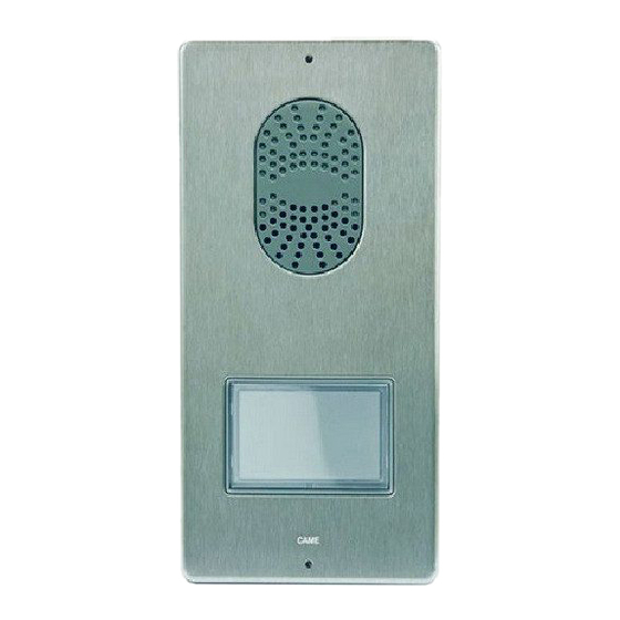
- Page 7 001CS1PLCO Wall mounting With the allen wrench unscrew the blocking screws and remove the plate A. Fix the given plugs and screw the entry panel B at the desired height. Run the hose with the system conductors B. Extract the plastic terminal cover and wire the connections C. Once all the connections have been made, re-insert the terminal covers.
- Page 8 Button module installation Insert the button module as highlighted F paying special attention to the top to bottom orientation H. Remove the glass and write the user names G, paying special attention to the orientation of the glass H. Accessories I ...
- Page 9 Features J Terminal board a BOUT Riser LED PROG Power supply 16-18 VDC – Terminal board – Earth BOUT Door lock release button (NA) Solenoid lock – 12 V 1 A max PROG key c and PROG LED Programming key and LED (see 'Programming' paragraph).
-
Page 10: Initial Programming
Connection example K PROG 001DC002AC 001DC002AC – BOUT – + – VLS/300 001DC005AC 001DC005AC Programming The kit is pre-configured to manage a single call originating from a single entry panel. One or more receivers answering the same call can be added, by following the below “Call button programming”... -
Page 11: Reprogramming Procedure
Exiting programming. Briefly press the PROG key i: the PROG LED off. NOTE. If no action is <1’’ performed, the procedure will automatically end PROG after 30 minutes. Reprogramming procedure >3’’ Entering Programming Mode. Press the PROG a key for at least 3 seconds and then release it (within 6 seconds) as soon as the LED PROG light flashes and the key back lighting lights up as illustrated in <6’’... -
Page 12: Connection Examples
Connection examples CAME GATE CAME GATE 001DC002AC 001DC002AC 001DC002AC 001DC002AC 001DC002AC 001DC002AC 001DC002AC 001DC002AC 001DC002AC – – – – – – 001DC011AC 001DC011AC 001DC011AC 001DC011AC 001D 001DC02EARY – 001CS1PLCO 001DC002AC – BOUT 001DC02EARY – 001DC002AC 001DC02EARY – –... - Page 13 001DC02EARY 001DC02EARY – – 001DC02EARY 001DC02EARY – – 001CS1PLCO 001DC002AC – BOUT 001DC02EARY CAME GATE – 001DC011AC 001CS1PLC0 – – 001DC011AC BOUT ...
- Page 14 Distances 001CS1PLCO 001DC002AC 001DC011AC Distances VCM/1D VCM/2D UTP/CAT 5 2x2,5mm La, Lb, Lc, Ld ≤250 m – ≤250 m – ≤25 m – – ≤60 m La(Lb, Lc, Ld)+Le ≤250 m...
- Page 16 CAME S.p.A. Via Martiri Della Libertà, 15 31030 Dosson di Casier - Treviso - Italy tel. (+39) 0422 4940 - fax. (+39) 0422 4941...
Need help?
Do you have a question about the 001DC011AC and is the answer not in the manual?
Questions and answers