Table of Contents
Advertisement
Advertisement
Table of Contents

Related Manuals for Xtreme Manufacturing XR5919


Summary of Contents for Xtreme Manufacturing XR5919
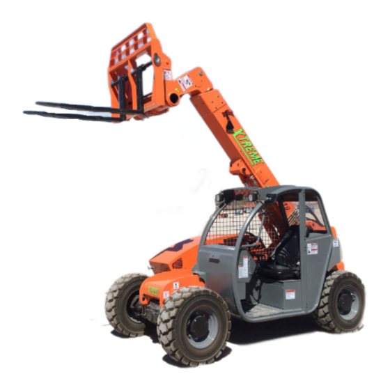
- Page 1 Operation and Safety Manual Tier 4 Final PN 24927-001...
- Page 2 Xtreme Manufacturing, LLC (w://www.xmfg.com/) is headquartered in Las Vegas, Nevada, and has fabrication facilities in Selma, California. In October 2013, Xtreme became the majority shareholder in Snorkel, a global aerial work platform manufacturer, which has manufacturing facilities in the US, UK & New Zealand, as well as a global sales distribution network. Find out more about Snorkel at www.snorkellifts.com.
-
Page 3: Table Of Contents
Table of Contents Table of Contents Description Page Description Page Operator Seat Introduction Operator Seat Controls General Replacement Manuals Backrest Angle Adjustment Lever Fore and Aft Adjustment Lever Model/Serial Number Plate Seat Belt Orientation Safety Rear View Mirrors Safety Disclaimer Controls and Indicators Travel Select Lever Signal Words... - Page 4 Table of Contents Table of Contents Description Page Attachments Attachment Disclaimer Fork Ratings Standard Carriage Operation Quick Attach System Load Handling Boom Lift Point Suspended Loads Pick Up a Load Carry a Load Place a Load Load Shift Load Capacity Charts Preventive Maintenance Establishing a Maintenance Program Maintenance Schedule...
-
Page 5: Introduction
Right side, left side, front, and rear are directional references Replacement Manuals given from the operator’s seat when facing forward. RIGHT Replacement manuals for the XR5919 Reach Forklift can be obtained by contacting our parts department by phone or visiting our website: Xtreme Manufacturing Phone: (800) 497-1704 www.XMFG.com... -
Page 6: Safety
Warning Safety Disclaimer WARNING (Orange) used with the safety alert symbol Xtreme Manufacturing reserves the right to make technical indicates a potentially hazardous situation which, if not changes for product improvement. This manual may contain avoided, could result in death or serious injury. - Page 7 Safety Read Operator Read Maintenance General Safety Manual Before Manual Before Alert Symbol Operating This Working On Forklift This Forklift Read Material DO NOT OPERATE! Know First Aid Safety Data Instructions And/ Forklift Down Sheets (MSDS) For Or Locations On For Service Or Chemicals And Work site...
- Page 8 Safety DO NOT DO NOT Fasten Jump While Allow Riders Seat Dismounting On Auxiliary Belt The Forklift Attachments Set Parking DO NOT Allow DO NOT Allow Brake To OFF Riders On Forklift Riders On Or In Disengage Frame Or Fenders The Operator Cab Parking Brake Set Parking Brake...
-
Page 9: Employer Responsibility
Safety Employer Responsibility Operator Qualifications Under Occupational Safety and Health Administration (OSHA) Operators must be in good physical and mental condition, rules, employers are required to train workers about hazards with appropriate reflexes, reaction time, vision, depth related to operating and maintaining the forklift. Successful perception, and hearing. -
Page 10: Mounting/Dismounting
Safety Warning Mounting/Dismounting • Operate the forklift only on firm, stable surfaces. Holes, Warning obstructions, debris, loose fill, and other work site hazards could result in death or serious injury. Failure to use proper safety procedures when mounting • DO NOT allow bystanders in the work area. and dismounting the forklift could result in death or serious •... -
Page 11: Before Starting Forklift
Safety Warning Warning Perform a pre-operation inspection and functional tests at the beginning of each work shift. Perform the pre-operation inspection first. DO NOT perform the pre-operation inspection with the engine running or hot. Wear appropriate protective clothing. Personal protective Allow the engine and associated components to cool before equipment can include, but is not limited to hardhat, performing an inspection. -
Page 12: Operation Safety
Safety the forklift cannot be leveled using the frame sway control, Warning do not attempt to raise or place load. Reposition forklift or have the surface leveled. Operators must be properly trained and qualified to operate this specific forklift. Warning Know the location, learn the specific purpose, and demonstrate safe and proper use of all To prevent death, serious injury, or prop-... - Page 13 Safety DO NOT shift through multiple gears with a Caution single turn of the gear select lever. Allow the engine speed to slow down before shifting to Never attempt to create Diesel Exhaust Fluid by mixing agri- the next lower gear. Improper use of the gear cultural grade urea with water.
-
Page 14: Load Safety
Safety Follow appropriate procedures to prevent Load Safety sudden changes in forklift speed that could result in death or serious injury. Warning • Slow the forklift to the appropriate speed before de- Failure to follow proper safety procedures scending a slope and before loading or unloading a when lifting, lowering, and traveling with a trailer. -
Page 15: Attachments
Safety Attachments Forklift Maintenance Warning Warning Improper connection of an auxiliary attachment could re- Follow manufacturer’s instructions proper sult in death or serious injury. Attachments not locked into maintenance to make sure the forklift continues to meet place can become unstable and fall on the operator or other manufacturer’s specifications. -
Page 16: Jump Starting
IMPORTANT - In case of internal contact, DO NOT give fluids The parking brake can be manually released to tow the forklift. In this condition, it is pos- that induce vomiting. sible for the forklift to move suddenly when the brakes are released, which could result Warning in death, serious injury, or property damage. -
Page 17: Dead Engine Towing
Safety Dead Engine Towing Parking Brake Release (Front Axle) Warning Block all four wheels. Failure to do so could result in death or serious injury from vehicle roll away. 1. Block all four wheels to prevent the vehicle from moving once the parking brake is disabled. -
Page 18: Labels
Labels Labels Left Side View INNER BOOM Fig 5. Label Legend (Left Side) Right Side View Fig 6. Label Legend (Right Side) Operation Manual... - Page 19 Labels Front View Rear View Fig 7. Label Legend (Front) Fig 8. Label Legend (Rear) Cab View 18086-101 Fig 9. Label Legend (Cab) Operation Manual...
- Page 20 Xtreme “X” 18022-001 Warning, Tip Over Hazard 18402-000 Boom Lettering Zones 18023-001 Warning, Welding and 18406-000 Required Tire Pressure Modification Hazard 18400-000 XR5919 18025-100 Warning, Falling Hazard 18314-000 Lift Point 18026-100 Warning, Unrestrained Operator Hazard 18086-101 Dexron III (dash) 18027-001...
-
Page 21: Replacement Labels
Replacement Labels Replacement labels can be obtained by contacting Xtreme Manufacturing at (800) 497-1704. Please have the appropri- ate label number available when you call. Parking Brake Lights Boom Rear Front Hazard Turn Steering Front and Rear Wheels Must Be Centered Before Engaging. - Page 22 Labels 18016-100 7) 18015-001 8) 18016-100 18018-100 9) 18017-001 10) 18018-100 18019-100 11) 18018-002 12) 18019-100 Operation Manual...
- Page 23 Labels 18020-100 18021-100 13) 18020-100 14) 18021-100 15) 18022-001 16) 18023-001 18025-100 18026-100 17) 18025-100 18) 18026-100 Operation Manual...
- Page 24 Labels 19) 18027-001 20) 18031-001 WARNING JOYSTICK ENABLED CONTROL FORK TILT BOOM DOWN BOOM RETRACT EXTEND FORK TILT JOYSTICK CONTROL ENABLE 18408-000 21) 18032-001 22) 18408-000 18041-100 18323-000 23) 18323-000 24) 18041-100 Operation Manual...
- Page 25 Labels 18082-100 25) 18318-000 26) 18082-100 18086-100 18083-100 27) 18083-100 28) 18086-100 18090-100 29) 18090-100 30) 18312-000 Operation Manual...
- Page 26 Labels 18315-000 31) 18315-000 32) 18326-000 18044-000 33) 18325-000 18402-000 34) 18402-000 REQUIRED TIRE PRESSURE 80 PSI 18400-000 18406-000R01 35) 18406-000R01 36) 18400-000 Operation Manual...
- Page 27 Labels 18086-101 18314-000 37) 18314-000 38) 18086-101 CAUTION EQUIPMENT DAMAGE Wait at least two (2) minutes after shutting engine off before setting the battery disconnect switch to OFF. Equipment damage may occur if the engine control systems are not allowed to shutdown properly.
-
Page 28: Features
Features Features Standard Equipment Optional Equipment Feature Description Feature Description Boom Two (2) section boom Options Enclosed cab with heat Boom equipped with slide pads Enclosed cab with heat & A/C Chassis Sealed pivot pins for extended service periods Heater/defroster/windshield wiper Side mounted engine Work light package Lights... -
Page 29: Specifications
Specifications Specifications Performance Standard Equipment Capacity ... . 5,900 lbs Heavy-duty Frame/Chassis Lift Height ... 19’ Heavy-duty Boom Forward Reach ..11’ Robust Wiring Frame Leveling L/R . -
Page 30: Operator Cab
Operator Cab Operator Cab Warning Accessory Outlet A brief description of controls, indicators, and A 12 Volt accessory outlet is provided as a power source for instruments is provided as a convenience for personal items, such as a radio or cell phone (10 amps max). the operator. -
Page 31: Service Brake Pedal
Operator Cab Service Brake Pedal Horn Button Press the service brake pedal to slow or stop the forklift. The Press the horn button to sound the horn. service brake pedal activates the service brakes on the front (2) wheels. Fig 15. Horn Button Fig 13. -
Page 32: Backrest Angle Adjustment Lever
Operator Cab Backrest Angle Adjustment Lever Seat Belt Pull the backrest angle adjustment lever up to release the seat Warning backrest lock. Adjust the angle of the backrest and release the lever to lock the backrest to the desired angle. Always check the condition of the seat belt and mounting hardware before operating the forklift. -
Page 33: Rear View Mirrors
Operator Cab 1. Grasp the free end of the seat belt (located on the left side of the seat) and make sure the belt webbing is not twisted or entangled in any portion of the seat assembly. 2. Pull the retractable seat belt across your lap. Position the seat belt as low on your body as possible. -
Page 34: Light Switches
Operator Cab The Steering Select switch has three (3) steering positions: Light Switches Crab, Two Wheel Steering (2W), and Four Wheel Steering (4W). The Light Switches control the boom and cab lights. Fig 25. Steering Select and 2-Wheel Rear Switches Fig 23. - Page 35 Operator Cab coolant in the engine cooling system. After starting the fork- D. HIGH HYDRAULIC OIL TEMP lift, allow time for the Engine Temp Gauge to begin moving The hydraulic oil temperature indicator illuminates when the before operating the forklift. After the engine has sufficiently oil temperature is above 1800 F.
- Page 36 Operator Cab E. ENGINE SHUTDOWN J. TRANSMISSION DIRECTION The Engine Shutdown Indicator will be displayed when there The transmission direction indicator displays whether the is a serious engine fault and the engine should be shut down. transmission is in FORWARD, NEUTRAL or REVERSE. Automatic shut down is imminent.
-
Page 37: Display Features
Operator Cab Display Features The display allows the operator to view vital engine information and other critical functions, including gauge display, engine diagnostics to monitor engine condition and performance, fault codes, and warning lights. POWER UP When the ignition is turned on, the display powers up and defaults to GAUGE DISPLAY mode. - Page 38 Operator Cab Fig 40. User Settings, Display Style B Fig 37. Engine Diagnostics Screenshot , Display Style B For example, the display style B has the following adjustable user settings: CLOCK ADJUSTMENT • Ambient light (day or night) For machines equipped with the display style B, pushing the •...
- Page 39 Operator Cab Fig 42. Utilities, Display Style B Fig 45. Edit Service Reminders Screenshot , Display Style B SERVICE REMINDERS HIDDEN UTILITIES Pressing the corresponding SERVICE REMINDERS soft button The machines equipped with the display style B have a will display data pertaining to maintenance schedules. HIDDEN UTILITIES menu.
- Page 40 Operator Cab PDM DIAGNOSTICS SYSTEM SETTINGS Pressing the PDM DIAGNOSTICS soft button from the HIDDEN This sub-menu is used by developers and is accessed from the UTILITIES menu will display the status of the Power Distribu- HIDDEN UTILITIES menu by pressing the corresponding soft tion Module.
-
Page 41: Multifunction Joystick Controller
Operator Cab Multifunction Joystick Controller (Joystick) Boom Control Handle Functions Function Purpose Aux Button 1 Control auxiliary direction 1 Enable LED Aux Button 2 Control auxiliary direction 2 Aux Button 1 Enable Trigger Trigger must be enabled for other functions of the control handle to Aux Button 2 operate Tilt Thumbstick... -
Page 42: Boom Angle Indicator
Operator Cab Boom Angle Indicator The boom angle indicator is located on the left side of the boom and is visible from the operator’s seat. Use the boom angle indicator to determine the boom angle when referring to load capacity charts. Refer to the LOAD CAPACITY CHARTS section of this manual for more information. -
Page 43: Boom Extend Letters
Operator Cab Frame Level Indicator Boom Extend Letters The frame level indicator is mounted on the upper right As the boom is extended, the boom extend letters on the left corner of the operator’s cab. The frame level indicator allows side of the boom are visible to the operator. -
Page 44: Operation
Operation Operation Pre-Operation Inspection Caution To perform the pre-operation inspection make sure the Contact with hot surfaces and the exhaust forklift is NOT running, the engine is cool, the forklift is parked pipe after the forklift has been operated on level ground, the boom is completely retracted, and the could result in serious personal injury. - Page 45 Operation Warning Warning Wear eye protection when starting a forklift with jump start cables. Improper jump start procedures could cause the battery to ex- plode, which could result in death or serious injury. Lead-acid batteries produce flammable and potentially ex- •...
-
Page 46: Pre-Operation Inspection Checklist
Operation Pre-Operation Inspection Checklist Walk around the ENTIRE forklift while visually performing the pre-operation inspection. Check that “Do Not Operate” tags have not been placed on the forklift. Check that load capacity charts are legible. Check condition and operation of the seat belt and mounting hardware. Check that Operation and Safety Manual is in the protective case and legible. -
Page 47: Functional Tests
Operation Release the parking brake. Functional Tests Operate the forklift in forward and reverse. Test the service and parking brakes. Warning • Apply the service brake pedal after the forklift Perform a pre-operation inspection and func- begins to move and the forklift should stop tional tests at the beginning of each work immediately. -
Page 48: Operator Maintenance
Operation Operator Maintenance Never remove the radiator cap while the engine is hot. The cooling system is under pressure. Hot coolant could cause severe burns or eye injury. Wear protective clothing and safety glasses. Check coolant reservoir level only when the engine is cool to touch. -
Page 49: Before Starting Forklift
Operation Before Starting Forklift Warning Failure to use proper safety procedures when mounting and dismounting the forklift could result in death or serious injury. • Keep steps clear of dirt, mud, snow, ice, debris, and oth- er hazards. Face the forklift for mounting or dismount- ing. -
Page 50: Starting Forklift
Operation 4. Release key immediately after the engine starts. The Starting Forklift Ignition Switch will automatically return to RUN. Normal Starting Caution Release the key immediately once the engine starts. If the Warning engine does not start, DO NOT crank the starter motor con- tinuously for more than 15 seconds. -
Page 51: Forklift Travel
Operation Two Wheel Front Steering (2W) Forklift Travel Two wheel (2W) steering allows the front wheels to turn in the same direction as the Steering Modes steering wheel. The rear wheels remain in a fixed forward position. Two wheel (2W) steering is useful for traveling at higher Warning speeds. -
Page 52: Starting Travel
Operation Starting Travel Warning Indicators and Fault Codes Warning Warning Use proper safety procedures and avoid A fault condition may trigger a popup dialog hazardous situations while operating the box on the display describing the nature of forklift to prevent death, serious injury, or the fault during operation. -
Page 53: Tier Iv Engine
Operation Tier IV Final Engine ENGINE STOP INDICATOR The Engine Stop Indicator is displayed with a flashing Engine Warning Indicator when ENGINE WARNING INDICATOR the engine is either shut down or an engine A steady Engine Warning Indicator by itself shutdown is imminent. -
Page 54: Diesel Exhaust Fluid (Def)
Operation High Exhaust Diesel High Exhaust Diesel Engine should be shutdown by Engine should be shutdown by Engine is either shutdown or automatic Engine Engine FLASH Shutdown operator. Automatic shutdown will Shutdown operator. Automatic shutdown will Temperature Particulate Engine Oil Temperature Particulate shut down is imminent... -
Page 55: Changing Travel Direction
Operation Changing Travel Direction Refueling Warning Warning Make sure the forklift comes to a complete Engine fuel is flammable and stop before moving the travel select lever. A can cause a fire or explosion sudden change in direction of travel, while resulting in death or serious in- carrying a load, can reduce stability and/or jury. -
Page 56: Attachments
Xtreme Manufacturing assumes no liability for any third party attachment that would alter the center of gravity or stability. -
Page 57: Standard Carriage Operation
Operation Quick Attach System Standard Carriage Operation The standard carriage uses manually adjustable forks and can This forklift includes a quick attach system that allows for easy be tilted up or down by using the thumb stick on the control attachment changes. - Page 58 Operation 4. Raise the boom until pivot pins (A) have seated fully in at- tachment hooks (B). Fig 75. Quick Attach Pin Keeper Fig 73. Raise Boom Until Pivot Pins (A) Are Fully Seated in Attachment Warning Hooks (B) Hydraulic attachments have a maximum 5.
- Page 59 Operation Attachment Removal NOTE: To remove a standard carriage with forks, spread the forks apart on the carriage shaft. This provides adequate sup- port for the carriage to stand alone. 1. Bring the forklift to a complete stop. 2. Move the travel select lever to NEUTRAL (N). 3.
-
Page 60: Load Handling
Operation Load Handling Danger Warning Death or serious injury by electrocution DO NOT exceed the manufacturer’s rated load will result from contact with or inadequate for any auxiliary attachment. Any attempt to clearance with energized power lines or lift or carry loads in excess of the manufactur- apparatus. -
Page 61: Boom Lift Point
Operation Boom Lift Point Suspended Loads Warning Warning DO NOT exceed rated capacities. Any attempt Avoid carrying a suspended load. If necessary, to lift or carry loads in excess of those shown secure the load by attaching it to the forklift on the load capacity charts could cause tie-downs and/or have another person assist forklift tip over, loss of load, or structural... -
Page 62: Carry A Load
Operation Load capacity charts, located in the center of the dash panel, Carry A Load are provided to assist the operator in determining how to safely operate the boom to pick up, carry, and set down a load 1. Carry the load as low as possible while maintaining good with the reach forklift, including what angle, how high, and ground clearance and visibility. - Page 63 5. Operator reads load capacity chart for attachment carriage to learn it will be safe to place the load at any boom angle with the boom extend letter “D” showing. XR5919 LOAD CHART - STANDARD CARRIAGE 2 FT LOAD RATINGS...
-
Page 64: Preventive Maintenance
Preventive Maintenance Preventive Maintenance Establishing a Maintenance Program Check engine hoses and connections for leaks, damage, and tightness The hour meter displays elapsed engine operating hours. Use Check radiator hoses for leaks, damage, and tightness the hour meter and the schedules contained in this section to establish a comprehensive preventive maintenance program. - Page 65 Preventive Maintenance After Every 1,000 Hours of Operation After Every 250 Hours of Operation Comply with 50-Hour Maintenance Requirements Comply with 50-Hour Maintenance Requirements Comply with 250-Hour Maintenance Requirements Change engine oil and filter Comply with 500-Hour Maintenance Requirements Check air filter (replace if necessary) Change axle wheel-end and differential oil &...
-
Page 66: Boom Emergency Lower Down Valve
Preventive Maintenance Locate needle valve on extend cylinder. Loosen nut on Boom Emergency Lower Down Valve valve, then loosen valve with hex wrench. Both of the lift and extend cylinders are equipped with a needle valve which allows the cylinder to retract without the direct assist of the machine’s hydraulic power. - Page 67 Preventive Maintenance 11. When boom is fully lowered, tighten valve with hex wrench, then tighten nut to secure valve. Fig 92. Lift Cylinder Lower Down Valve 10. Thread a 125mm long M8-1.25 capscrew into the manual operator of the lift/lower section on the proportional control valve (first section from boom side, on top of the valve) and use it to manually operate the valve to lower the boom.
-
Page 68: Lockout / Tagout
Lockout / Tagout Lockout/Tagout is off. THROWING THE BATTERY DISCONNECT SWITCH TOO EARLY MAY CONFUSE THE ECU IF THE WRITING PROCESS IS Do Not Operate - Accident Prevention Tags NOT COMPLETED. Before beginning any maintenance or service, place a Do Not Operate Tag on both the starter key switch and the steering wheel, stating that the vehicle should not be operated. -
Page 69: Do Not Operate Tags
Lockout / Tagout Do Not Operate Tags Operation Manual... - Page 70 Lockout / Tagout Operation Manual...
- Page 71 Lockout / Tagout Operation Manual...
- Page 72 1415 W. BONANZA RD LAS VEGAS, NV 89106 (702) 636-2969 (800) 497-1704 www.XMFG.com XR5959 TIER 4 FINAL OPERATION AND SAFETY MANUAL PN 24927-001 DZ...
Need help?
Do you have a question about the XR5919 and is the answer not in the manual?
Questions and answers