Table of Contents
Advertisement
Advertisement
Table of Contents

Related Manuals for HP E-MSM720


Summary of Contents for HP E-MSM720
- Page 1 HP E-MSM720 Wireless Controllers Installation Guide...
- Page 3 HP E-MSM720 Wireless Controllers Installation Guide (Draft)
- Page 4 HP E-MSM720 Access Controller J9693A HP shall not be liable for technical or editorial errors or HP E-MSM720 Premium Mobility Controller J9694A omissions contained herein. Hewlett-Packard assumes no responsibility for the use or reliability of its software on equipment that is not furnished by Hewlett-Packard.
-
Page 5: Table Of Contents
3. Mount the E-MSM720 ........ - Page 6 HP Customer Support Services ........4-1...
- Page 7 EMC Regulatory Statements ........C-8 U.S.A.
-
Page 9: Identifying E-Msm720 Physical Features
Identifying E-MSM720 Physical Features Unpacking the E-MSM720 Unpack your E-MSM720 and verify that you have received these items: E-MSM720 Controller ■ ■ Console port serial cable (DB-9 to RJ-45) ■ Documentation Safety and Regulatory information ■ ■ Software License, Warranty, and Support information ■... -
Page 10: Identifying Front-Panel Features
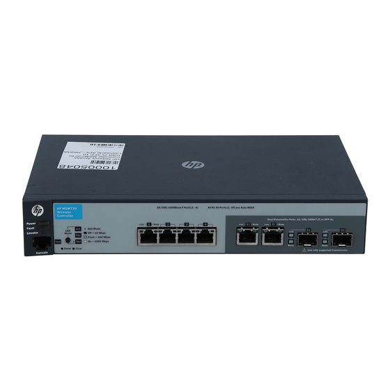
Identifying E-MSM720 Physical Features Identifying Front-panel Features Identifying Front-panel Features It is important to be aware of the E-MSM720 front panel features as they are referenced throughout this document. 1 Power, Fault, and Locator LEDs 5 Console port 2 LED Mode select button and... -
Page 11: Leds
On briefly after the E-MSM720 is powered on or reset, at the beginning of E-MSM720 self test. If this LED is on for a prolonged time, the E- MSM720 has encountered a fatal hardware failure, or has failed its self test. -
Page 12: Port Leds
• the mini-GBIC is not supported by the current software • the mini-GBIC is not a genuine HP Mini-GBIC and is not supported • the mini-GBIC is an “A” version in an E-MSM720 that requires a “B” version or later. -
Page 13: Led Mode Select Button And Indicator Leds
Identifying E-MSM720 Physical Features Identifying Front-panel Features LED Mode Select Button and Indicator LEDs The Port Mode LED shows Activity (Act LED on), Duplex (FDx LED on), or Speed (Spd LED on). Press the LED Mode Select button to sequence through the three modes. -
Page 14: Resetting To Factory Defaults
Clear button flash three times, then release the Clear button. Using the Console Port The Console port is used to connect a console to an E-MSM720 by using the supplied RJ-45 to DB9 cable. This is used for the CLI (Command Line... -
Page 15: Installing The E-Msm720
The mark is your assurance that the power cord can be used safely with the E-MSM720. If the supplied power cord does not fit, contact HP Networking support. -
Page 16: Installation Procedures
E-MSM720 and having an appropriate location for the E-MSM720. Verify the E-MSM720 passes self test (page 2-3). Plug the E-MSM720 into a power source and observe that the LEDs on the E-MSM720’s front panel indicate correct E-MSM720 operation. Mount the E-MSM720 (page 2-5). -
Page 17: Prepare The Installation Site
Installation Location - Before installing the E-MSM720, plan its location and orientation relative to other devices and equipment: • In the front of the E-MSM720, leave at least 7.6 cm (3 inches) of space for the twisted-pair and fiber-optic cabling. •... - Page 18 Installation Procedures N o t e The E-MSM720 also does not have a power switch. It is powered on when the external AC/DC power adapter is connected to the E-MSM720 and the adapter power cord is connected to a power source. The external AC/DC power adapter automatically adjusts to any voltage between 100-240 volts and either 50 or 60 Hz.
-
Page 19: Led Behavior
In addition, it can configure the LAN ports to operate at low power if a link is not detected. 3. Mount the E-MSM720 After the E-MSM720 passes self test, it is ready to be mounted in a stable location. The E-MSM720 can be mounted in these ways: in a rack or cabinet ■... -
Page 20: Rack Or Cabinet Mounting
The mounting brackets have multiple mounting holes and can be rotated allowing for a wide variety of mounting options. These include mounting the E-MSM720 so that its front face is flush with the face of the rack, or mounting it in a more balanced position. - Page 21 For safe reliable installation, only use the screws provided in the accessory kit to attach the mounting brackets to the E-MSM720. Hold the E-MSM720 with attached brackets up to the rack and move it vertically until rack holes line up with the bracket holes, then insert and tighten the four number 12-24 screws holding the brackets to the rack.
-
Page 22: Wall Or Under-Table Mounting
Installing the E-MSM720 Installation Procedures Wall or Under-Table Mounting You can mount the E-MSM720 on a wall with either the front or rear panel facing up. W A R N I N G The network ports must be facing up. Do not mount the E-MSM720 with ports facing down. -
Page 23: Using A Kensington Security Cable
Installing the E-MSM720 Installation Procedures Attach the rubber feet to the four corners on the bottom of the E-MSM720 within the embossed angled lines. Use a sturdy surface in an uncluttered area. You may want to secure the networking cables and E-MSM720 power cord to the table leg or other part of the surface structure to help prevent tripping over the cords. -
Page 24: Connect The Network Cables
Push the RJ-45 plug into the RJ-45 port until the tab on the plug clicks into place. When power is on for the E-MSM720 and for the connected device, the Link LED for the port should light to confirm a powered-on device (for example, an end node) is at the other end of the cable. -
Page 25: Installing Or Removing Optional Mini-Gbics
C a u t i o n Hot swapping transceivers is supported. You can install or remove a transceiver with the E-MSM720 powered on, a reset will not occur. However, rapid hotswaps are not recommended. Wait a few seconds for the Mode LED to turn on (during initialization), and then turn off. -
Page 26: Installing The Mini-Gbics
Installing the mini-GBICs: Remove the protective plastic cover and retain it for later use. Hold the mini- GBIC by its sides and gently insert it into either of the slots on the E-MSM720 until the mini-GBIC clicks into place. W A R N I N G The HP mini-GBICs are Class 1 laser devices. -
Page 27: Msm720 Initial Configuration
Disconnect any cable from your computer Ethernet ports, and disable any wireless connection. b. Connect E-MSM720 port 1 (ports 2 to 4 can also be used) to your computer Ethernet port. Connect E-MSM720 port T5 or T6 (or if enabled, port S5 or S6) to a network with Internet access or to the PC port of a DSL modem or equivalent. - Page 28 On the Login page, enter admin for Username and admin for Pass- word and then select Login. d. On the HP End User License Agreement page, read the agreement and then select Accept HP End User License Agreement. On the product registration page it is recommended that you register your product now by selecting Register Now.
- Page 29 E-MSM720 Initial Configuration Perform Initial Configuration The last page in the workflow lists all configuration settings that will be applied, for example: Look over these settings to make sure they are what you want. Select Apply to apply your changes. Alternatively, select Back to go to the previous workflow page or select Cancel to discard your workflow settings and exit the workflow.
- Page 30 E-MSM720 Initial Configuration Perform Initial Configuration d. After applying your changes, a confirmation page appears showing the menu paths to each configuration page associated with the Basic controller setup workflow. For example: Select Start a new workflow if you now wish to run the Guest or...
-
Page 31: Support And Other Resources
24 hours a day, seven days a week through the use of a number of automated electronic services. See the Software License, Warranty and Support booklet that came with your E-MSM720 for information on how to use these services to get technical support. The HP Web site: www.hp.com/networking/support... - Page 32 Support and Other Resources HP Customer Support Services...
-
Page 33: Specifications
15% to 95% at 65C (149F) (non-condensing) Maximum altitude 3.0 Km (10,000 ft)* 4.57 Km (15,000 ft) The operating maximum altitude should not exceed that of any accessory being connected to an E-MSM720. Acoustic Acoustic Power: 0 dB, Pressure: 0 dB... -
Page 34: Safety
Specifications Specifications Safety CE Labeled and UL Listed. Complies with: ■ EN 60950-1:2001 + A11:2004 ■ IEC 60950-1:2001 EN 60825-1:1994 +A1+A2 / IEC 60825-1:1993 +A2 Class 1 ■ ■ cUL (CSA 22.2 No. 60950) ■ UL 60950-1 UL Listed ■ ■... -
Page 35: Ethernet
Specifications Cabling Standards Ethernet Four RJ-45 auto-sensing 10/100/1000 (IEEE 802.3 Type 10Base-T, IEEE ■ 802.3u Type 100Base-TX, IEEE 802.3ab Type 1000Base-T); Duplex: 10Base-T/100Base-TX: half or full; 1000Base-T: full only. ■ 2 dual-personality ports: each port can be used as either an RJ-45 10/100/ 1000 port (IEEE 802.3 Type 10Base-T;... -
Page 36: Cabling And Technology Information Specifications
Specifications Cabling and Technology Information Specifications Table A-1. Technology Standards and Safety Compliance (Continued) Laser safety information Technology Compatible with these IEEE EN/IEC standards standard ("mini-GBIC") Lasers compliance 1000-BX IEEE 802.3ah 1000BASE-BX10 EN/IEC 60825 Class 1 Laser Product Laser Klasse 1 Cabling and Technology Information Specifications Table A-2. -
Page 37: Technology Distance Specifications
Equal-Level Far-End Crosstalk (ELFEXT) and Return Loss. When testing your cabling, be sure to include the patch cables that connect the E-MSM720 and other end devices to the patch panels on your site. The patch cables are frequently overlooked when testing cable and they must also comply with the cabling standards. - Page 38 Specifications Cabling and Technology Information Specifications...
-
Page 39: Installing The Patch Cord
Installing the Patch Cord As shown in the illustration below, connect the patch cord to the HP transceiver with the section of single mode fiber plugged in to the Tx (transmit) port. - Page 40 Mode Conditioning Patch Cord (Fiber Cables) If you connect the patch cord directly to the network cabling, you may need to install a female-to-female adapter to allow the cables to be connected together. Gigabit-LX port To network multimode Mode Conditioning cabling Patch Cord Single mode section plugs into Tx...
-
Page 41: C Safety And Emc Regulatory Statements
There are no user-serviceable parts inside these products. Any servicing, adjustment, maintenance, or repair must be performed only by service-trained personnel. These products do not have a power E-MSM720; they are powered on when the power cord is plugged in. -
Page 42: Informations Concernant La Sécurité
Safety and EMC Regulatory Statements Informations concernant la sécurité Informations concernant la sécurité Symbole de référence à la documentation. Si le produit est marqué de ce symbole, reportez-vous à la documentation du produit afin d'obtenir des informations plus détaillées. WARNING Dans la documentation, un WARNING indique un danger susceptible d'entraîner des dommages corporels ou la mort. -
Page 43: Hinweise Zur Sicherheit
Safety and EMC Regulatory Statements Hinweise zur Sicherheit Hinweise zur Sicherheit Symbol für Dokumentationsverweis. Wenn das Produkt mit diesem Symbol markiert ist, schlagen Sie bitte in der Produktdokumentation nach, um mehr Informationen über das Produkt zu erhalten. WARNING Eine WARNING in der Dokumentation symbolisiert eine Gefahr, die Verletzungen oder sogar Todesfälle verursachen kann. -
Page 44: Considerazioni Sulla Sicurezza
Safety and EMC Regulatory Statements Considerazioni sulla sicurezza Considerazioni sulla sicurezza Simbolo di riferimento alla documentazione. Se il prodotto è contrassegnato da questo simbolo, fare riferimento alla documen- tazione sul prodotto per ulteriori informazioni su di esso. WARNING La dicitura WARNINGdenota un pericolo che può causare lesioni o morte. -
Page 45: Consideraciones Sobre Seguridad
Safety and EMC Regulatory Statements Consideraciones sobre seguridad Consideraciones sobre seguridad Símbolo de referencia a la documentación. Si el producto va marcado con este símbolo, consultar la documentación del producto a fin de obtener mayor información sobre el producto. WARNING Una WARNING en la documentación señala un riesgo que podría resultar en lesiones o la muerte. -
Page 46: Safety Information (Japan
Safety and EMC Regulatory Statements Safety Information (Japan) Safety Information (Japan) J a p a n P o w e r C o r d W a r n i n g... -
Page 47: Safety Information (China
Safety and EMC Regulatory Statements Safety Information (China) Safety Information (China) -
Page 48: Emc Regulatory Statements
Safety and EMC Regulatory Statements EMC Regulatory Statements EMC Regulatory Statements U.S.A. FCC Class A This equipment has been tested and found to comply with the limits for a Class A digital device, pursuant to Part 15 of the FCC Rules. These limits are designed to provide reasonable protection against interference when the equipment is operated in a commercial environment. -
Page 49: Korea
Safety and EMC Regulatory Statements EMC Regulatory Statements Korea Taiwan... -
Page 50: European Community Declaration Of Conformity
This number should not be confused with the marketing name or the product numbers. 2) This product was tested with HP branded products only. Roseville, 14-June-2011 European Contact: Your local Hewlett-Packard Sales and Service Office or Hewlett-Packard GmbH, Department HQ-TRE, Herrenberger Straße 140, D-71034 Böblingen (FAX: + 49-7031-14-3143) -
Page 51: D Recycle Statements
Recycle Statements Waste Electrical and Electronic Equipment (WEEE) Statements Disposal of Waste Equipment by Users in Private Household in the European Union This symbol on the product or on its packaging indicates that this product must not be disposed of with your other household waste. - Page 52 Recycle Statements Waste Electrical and Electronic Equipment (WEEE) Statements Laitteiden hävittäminen kotitalouksissa Euroopan unionin alueella Jos tuotteessa tai sen pakkauksessa on tämä merkki, tuotetta ei saa hävittää kotitalousjätteiden mukana. Tällöin hävitettävä laite on toimitettava sähkölaitteiden ja elektronisten laitteiden kierrätyspisteeseen. Hävitettävien laitteiden erillinen käsittely ja kierrätys auttavat säästämään luonnonvaroja ja varmista- maan, että...
- Page 53 Recycle Statements Waste Electrical and Electronic Equipment (WEEE) Statements Smaltimento delle apparecchiature da parte di privati nel territorio dell'Unione Europea Questo simbolo presente sul prodotto o sulla sua confezione indica che il prodotto non può essere smaltito insieme ai rifiuti domestici. È responsabilità dell'utente smaltire le apparecchiature consegnan- dole presso un punto di raccolta designato al riciclo e allo smaltimento di apparecchiature elettriche ed elettroniche.
- Page 54 Para obter mais informações sobre locais que reciclam esse tipo de material, entre em contato com o escritório da HP em sua cidade, com o serviço de coleta de lixo ou com a loja em que o produto foi adquirido.
- Page 55 To learn more, visit www.hp.com/networking/ © Copyright 201 1 Hewlett-Packard Development Company, L.P. The information contained herein is subject to change without notice. The only warranties for HP products and services are set forth in the express warranty statements accompanying such products and services.
Need help?
Do you have a question about the E-MSM720 and is the answer not in the manual?
Questions and answers