HP VXI Pentium 75000 Series Hardware Installation And Configuration Manual
Hide thumbs
Also See for VXI Pentium 75000 Series:
- User manual (192 pages) ,
- Hardware installation and configuration manual (80 pages) ,
- User manual (20 pages)

Related Manuals for HP VXI Pentium 75000 Series


Summary of Contents for HP VXI Pentium 75000 Series
- Page 1 sales@artisantg.com artisantg.com (217) 352-9330 | Click HERE Find the Keysight / Agilent E6234A at our website:...
- Page 2 HP 75000 Series C VXI Pentium® Controller Hardware Installation and Configuration Guide HP E623xA HP VXI Pentium Controllers *E6232-90001* Manual Part Number: E6232-90001 Printed in U.S.A. E0897 Artisan Technology Group - Quality Instrumentation ... Guaranteed | (888) 88-SOURCE | www.artisantg.com...
- Page 3 Artisan Technology Group - Quality Instrumentation ... Guaranteed | (888) 88-SOURCE | www.artisantg.com...
-
Page 4: Warranty
This Hewlett-Packard product is warranted against defects in materials and workmanship for a period of three years from date of shipment. Duration and conditions of warranty for this product may be superseded when the product is integrated into (becomes a part of) other HP products. -
Page 5: Safety Symbols
Trademark and Copyright Notification Intel and Pentium are U.S. registered trademarks of Intel Corporation. Microsoft, Windows 95, and Windows NT are U.S. registered trademarks of Microsoft Corporation. Phoenix and PicoBIOS are registered trademarks of Phoenix Technologies, Ltd. Portions of this manual are copyright 1995 by Phoenix Technologies, Ltd. -
Page 6: Declaration Of Conformity
Supplementary Information: The product herewith complies with the requirements of the Low Voltage Directive 73/23/EEC and the EMC Directive 89/336/EEC (inclusive 93/68/EEC) and carries the "CE" mark accordingly. Tested in a typical configuration in an HP C-Size VXI mainframe. Jim White, QA Manager... - Page 7 Notes: Artisan Technology Group - Quality Instrumentation ... Guaranteed | (888) 88-SOURCE | www.artisantg.com...
-
Page 8: Table Of Contents
Contents Warranty ........................1 Safety Symbols ......................2 WARNINGS ......................... 2 Declaration of Conformity.................... 3 Chapter 1 Introduction ........................11 About this Manual ...................... 11 Overview........................13 Major Components ....................14 Front Panel ......................15 Where to Go Next ....................... 16 Chapter 2 Installing and Configuring the Hardware .............. - Page 9 Booting the Special BIOS Boot Diskette..............59 Appendix E Installing Additional DRAM Memory ............... 61 Memory Specifications ....................62 Ordering HP Memory ....................62 Referenced Memory Parts ..................63 Ordering Referenced Memory ..................63 Installation Procedure ....................64 Tools Required ....................64 SO DIMM Installation Requirements ..............
- Page 10 List of Figures Figure 1-1. The HP VXI Pentium Controller ............13 Figure 1-2. The Front Panel of the VXI Pentium Controller ......15 Figure 3-1. Main BIOS Setup Menu ..............28 Figure 3-2. IDE Adapter 0 Sub-Menus ............... 29 Figure 3-3.
- Page 11 List of Figures Artisan Technology Group - Quality Instrumentation ... Guaranteed | (888) 88-SOURCE | www.artisantg.com...
- Page 12 Environmental Specifications............55 Table C-2. VXI Pentium Controller Power Requirements......... 56 Table E-1. Memory Specifications..............62 Table E-2. HP Memory Upgrade Kits ..............62 Table E-3. DRAM Memory Parts List ............... 63 Table F-1. Phoenix NuBIOS Checkpoint Codes..........67 Table F-2.
- Page 13 List of Tables Artisan Technology Group - Quality Instrumentation ... Guaranteed | (888) 88-SOURCE | www.artisantg.com...
-
Page 14: Chapter 1 Introduction
Chapter 1 Introduction About this Manual Welcome to the HP VXI Pentium® Controllers: Hardware Installation and Configuration Guide. This guide explains how to install the VXI Pentium Controller hardware, including any peripherals you wish to connect to the controller. This guide then explains how to power up the controller and customize the controller’s configuration if the default, factory-set... - Page 15 BIOS from the floppy disk drive. • Appendix E - Installing Additional DRAM Memory explains how to install more SO DIMM DRAM in an HP VXI Pentium controller. • Appendix F - POST Beep Codes lists the Power-on Self-tests checkpoint codes and audible beeps codes issued if a failure is detected.
-
Page 16: Overview
Overview This guide supports several HP products in the HP VXI Pentium Controller family. The specific HP product number is marked on the side of the controller. The HP VXI Pentium Controller is an Intel Pentium-based, dual-slot, C-size computer which is PC-compatible and is designed to interface to the VXIbus and the EXMbus. -
Page 17: Major Components
Major Components The VXI Pentium Controller includes three major components: • An I/O base board, which contains integrated PCI peripherals for graphics, SCSI, Enhanced IDE, and Ethernet. The I/O base board also supports an RS-232 serial port, a parallel port, a keyboard, and a mouse. -
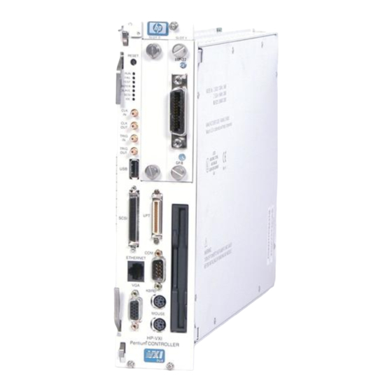
Page 18: Front Panel
Front Panel As shown below, the front panel of the VXI Pentium Controller spans two VXI slots. Figure 1-2. The Front Panel of the VXI Pentium Controller Chapter 1 Introduction Artisan Technology Group - Quality Instrumentation ... Guaranteed | (888) 88-SOURCE | www.artisantg.com... -
Page 19: Where To Go Next
LEDs, see Appendix A, “LEDs on the Front Panel.”) • 4 SMB connectors, including: CLK10 IN, CLK10 OUT, TRIGGER IN, and TRIGGER OUT. • 2 EXMbus slots. (Note that an HP-22 GPIB card is pre-installed in Slot 1.) • 3.5-inch floppy disk drive. •... -
Page 20: Installing And Configuring The Hardware
Chapter 2 Installing and Configuring the Hardware About this Chapter This chapter contains step-by-step instructions to help you set up the HP VXI Pentium Controller hardware. To install and configure the controller hardware, you need to complete the following steps. -
Page 21: Verify The Product Package
Note The Windows or the LynxOS operating system software, the appropriate HP I/O Libraries software, and the controller drivers and utilities software are all pre-loaded on the controller’s hard disk. Therefore, the following software CD-ROMs and floppy diskettes are included in your product package merely as a contingency, in case you ever need to re-install the software for any reason. -
Page 22: Check The Installation Location
Since the VXI Pentium Controller comes pre-loaded with a Microsoft Windows or the LynxOS operating system, HP I/O Libraries for Windows or HP SICL for LynxOS, and controller drivers and utilities software, you do not need to connect a CD-ROM drive to the controller unless you need to re-install the software for some reason. -
Page 23: Installing The Controller In The Vxi Card Cage
Therefore, if you wish to install only one more interface card, you may want to leave the existing HP-22 card in Slot 1 and install the new card in Slot 0. •... - Page 24 • Because the system BIOS for the controller is pre-configured for an HP-22 GPIB interface card in Slot 1 only, you will need to change the BIOS configuration if you make any interface card installation changes. For example, if you do any of the following, you will need to change the BIOS configuration: -- Add another interface card to Slot 0.
-
Page 25: Connecting The Peripherals
Connect a VGA or better monitor (15-pin, D-shell connector) to the VGA connector. • Optionally, connect an HP C2944D CD-ROM drive to the SCSI port. 22 Installing and Configuring the Hardware Chapter 2 Artisan Technology Group - Quality Instrumentation ... Guaranteed | (888) 88-SOURCE | www.artisantg.com... -
Page 26: Powering Up The Controller
Powering Up the Controller Pre-power Checklist Before you power up the VXI Pentium Controller, ensure that you have completed the following steps. 1. Installed any other EXM interface card(s) in the controller, if needed. 2. Connected all peripherals (including a keyboard, mouse, and monitor) to the controller. -
Page 27: Customizing The Controller's Bios
BIOS Setup Utility during the system boot process. 1. If you installed any other EXMbus interface card(s) in the controller (other than the HP-22 GPIB card pre-installed in Slot 1.) 2. If any default configuration value in the system BIOS is not suitable for your controller’s particular hardware setup. -
Page 28: Where To Go Next
The following subsections list the manual you should use next to complete the configuration of each controller. Software To continue the installation of the HP VXI Pentium Controller, please refer to the HP VXI Pentium Controllers: E623x Controller User’s Guide for the Installation and particular controller you are installing. - Page 29 26 Installing and Configuring the Hardware Chapter 2 Artisan Technology Group - Quality Instrumentation ... Guaranteed | (888) 88-SOURCE | www.artisantg.com...
-
Page 30: Using The Bios Setup Utility
This chapter explains the various menus, sub-menus, and fields in the BIOS (Basic Input/Output System) Setup utility that you can use to configure the HP VXI Pentium Controller hardware. Since the controller is shipped with all BIOS Setup values pre-configured, you only need to use this chapter if you want to make changes to the pre-configured, default BIOS value settings. -
Page 31: Main Bios Setup Menu
Main BIOS Setup Menu The Main BIOS Setup Menu is shown below. PhoenixBIOS Setup - Copyright 1985-95 Phoenix Technologies Ltd. Main Advanced Power Exit Item Specific Help System Time: [16:17:18] System Date: [03/01/96] <Tab>, <Shift-Tab>, or <Enter> selects field. Diskette A: [1.44 Mb, 3½”] Diskette B: [Not Installed]... -
Page 32: Ide Adapter 0 Sub-Menus
PCI/VME bridge. For more information, see the “Memory Shadow Sub-Menu” subsection later in this chapter. Boot Sequence: Sub-Menu The Boot Sequence Sub-Menu allows you to change the boot delay and boot sequence, and to disable several displays during the boot process, such as the SETUP prompt, POST (power-on self-test) errors, floppy drive check, and summary screen. - Page 33 Cylinder, Head, and Sectors/Track information, as listed on the label attached to the drive at the factory, must be entered manually on this sub-menu using the User Type, which is described below. Type: Select None if there is no IDE hard disk drive for this adapter. In the case where there is an IDE disk but the Autotype function (above) cannot be employed, then select the User type and enter the correct drive values for Cylinders, Heads, Sectors/Track, and Write Precomp (precompensation) for...
-
Page 34: Memory Cache Sub-Menu
Memory Cache This sub-menu controls the cachability of certain memory regions, as well as the settings of the Level 2 (L2) cache. The Memory Cache Sub-Menu is Sub-Menu shown below. PhoenixBIOS Setup - Copyright 1985-95 Phoenix Technologies Ltd. Main Memory Cache Item Specific Help External Cache: [Enabled]... -
Page 35: Memory Shadow Sub-Menu
Memory Shadow The term “shadowing” refers to the technique of copying code, such as BIOS extensions, from ROM into DRAM and accessing them from DRAM. Sub-Menu This allows the CPU to access the BIOS extensions faster and generally increases system performance if many calls to the BIOS extensions are made. -
Page 36: Boot Sequence Sub-Menu
Boot Sequence The Boot Sequence Sub-Menu allows you to change options for the boot sequence. This sub-menu is shown below. Sub-Menu PhoenixBIOS Setup - Copyright 1985-95 Phoenix Technologies Ltd. Main Boot Options Item Specific Help Boot Delay: <Tab>, <Shift-Tab>, or <Enter>... -
Page 37: Keyboard Features Sub-Menu
continues to attempt to boot despite any start-up error messages that are displayed. Note that this field only affects those errors that are configured at build-time to halt the system. The default is Enabled. Summary Screen: This field is used to enable or disable a summary of the system configuration, which is displayed before the operating system starts to load. -
Page 38: Advanced Menu
Advanced Menu The Advanced Menu contains settings for integrated peripherals, memory shadow, cache, and large disk access mode. The Advanced Menu is shown below. PhoenixBIOS Setup - Copyright 1985-95 Phoenix Technologies Ltd. Main Advanced Power Exit Item Specific Help Warning! Setting items on this menu to incorrect values <Tab>, <Shift-Tab>, or <Enter>... -
Page 39: Integrated Peripherals Sub-Menu
Integrated This sub-menu is used to configure the onboard serial (COM) and parallel (LPT) ports, as well as the onboard disk controllers. The Integrated Peripherals Peripherals Sub-Menu is shown below. Sub-Menu PhoenixBIOS Setup - Copyright 1985-95 Phoenix Technologies Ltd. Advanced Integrated Peripherals Item Specific Help COM port:... -
Page 40: Advanced Chipset Control Sub-Menu
Advanced Chipset This sub-menu allows you to control selected settings for the chipset that affect performance or function. The Advanced Chipset Control Sub-Menu Control Sub-Menu is shown below. PhoenixBIOS Setup - Copyright 1985-95 Phoenix Technologies Ltd. Advanced Advanced Chipset Control Item Specific Help DRAM Speed: [60ns]... - Page 41 either x32 or x36 SODIMMs. The default is Disabled. (Note that the VXI Pentium Controller is shipped with non-parity x32 DRAM.) 38 Using the BIOS Setup Utility Chapter 3 Artisan Technology Group - Quality Instrumentation ... Guaranteed | (888) 88-SOURCE | www.artisantg.com...
-
Page 42: Power Management Menu
Power Management Menu This menu provides control over the power management facilities. As shown below, only about one-half of the Power Management Menu fields are visible at any one time; however, for completeness, all of the menu fields are listed and explained in this section. Use the Page Up Page Down keys to display the other page of fields. - Page 43 3 hours 4 hours Suspend Timeout: This field enables and sets the inactivity duration required to elapse before the system is placed into Suspend Mode from Standby Mode, or it disables the Suspend Timeout. The values are the same as for the Standby Timeout, listed above.
- Page 44 Standby Wakeup Events This group of fields enables or disables the keyboard or mouse to cause a Standby Wakeup Event -- that is, these fields allow keyboard or mouse activity to return the system to full speed. Keyboard: This field enables or disables the Standby Wakeup Event for the keyboard.
-
Page 45: Exm Menu
FF for Slot 0 and D9 for Slot 1. Option Byte 1: This field selects the I/O address selection for the HP-22. The default is FF, which corresponds to the I/O address 370-377, 770-777, B70-B77, and F70-F77. Other possible values are:... -
Page 46: Exit Menu
Exit Menu The fields in this menu allow you to save value settings and exit BIOS Setup, or abandon value changes and exit. The Exit Menu is shown below. PhoenixBIOS Setup - Copyright 1985-95 Phoenix Technologies Ltd. Main Advanced Power Exit Item Specific Help Save Changes &... - Page 47 44 Using the BIOS Setup Utility Chapter 3 Artisan Technology Group - Quality Instrumentation ... Guaranteed | (888) 88-SOURCE | www.artisantg.com...
-
Page 48: Chapter 4 Troubleshooting
IDE disk error. Cycle the power to the controller to see if this problem rectifies itself. If the LED indicators are still in an abnormal state, please contact your HP Service and Support Center for assistance. See Appendix F, “POST Beep Codes”, for additional information that may be useful to service personnel. -
Page 49: Bios Error Messages
Setup to ensure the disk type is correctly Fixed Disk Controller Failure identified. If this does not fix the problem, contact your HP Service and Support Center for assistance. The disk type for drive A: or B: is not correctly Incorrect Drive A type - run SETUP identified in BIOS Setup. - Page 50 BIOS located the address where the parity error occurred, it will also display that address on the screen. Contact your HP Service and Support Center for assistance. A parity error was found in the I/O bus. If the...
-
Page 51: Problems After Configuring The Bios
This can be done via either the “Get Default Values” or the “Load Previous Values” selection in the Exit Menu of BIOS Setup. If after restoring the default or previous BIOS configuration values, your controller is still not functioning properly, contact your HP Service and Support Center for assistance. 48 Troubleshooting Chapter 4 Artisan Technology Group - Quality Instrumentation ... -
Page 52: Leds On The Front Panel
Appendix A LEDs on the Front Panel There are seven LED indicators on the front panel of the VXI Pentium Controller which provide information about the state of the controller. The following table lists the label, color, and meaning of each LED indicator. Table A-1. - Page 53 50 LEDs on the Front Panel Appendix A Artisan Technology Group - Quality Instrumentation ... Guaranteed | (888) 88-SOURCE | www.artisantg.com...
-
Page 54: I/O, Memory, And Irq Details
Appendix B I/O, Memory, and IRQ Details This appendix provides more detailed technical descriptions of the following for the VXI Pentium Controller: • VGA video controller, including its BIOS extension • SCSI controller, including its BIOS extension • Ethernet controller •... -
Page 55: Ethernet Controller
Ethernet Controller The Ethernet controller resides on the PCIbus and is mapped as PCI device number 2. It uses PCIbus interrupt INTB. Network booting is not supported. The Ethernet port supports only a 10-base-T interface. Memory Map Table B-1. Memory Map Pentium Address Range Region Cached... -
Page 56: Irqs (Interrupt Request Lines)
IRQ0 Timer IRQ1 Keyboard Controller IRQ2 Cascade Interrupt Input IRQ3 COM2 (Not externally available) Use for second HP-22 on Windows 95 IRQ4 COM1 IRQ5 ECP Printer Port (LPT1) Use for second HP-22 on Windows NT IRQ6 3.5-inch Disk Drive IRQ7... - Page 57 54 I/O, Memory, and IRQ Details Appendix B Artisan Technology Group - Quality Instrumentation ... Guaranteed | (888) 88-SOURCE | www.artisantg.com...
-
Page 58: Appendix C Specifications
Appendix C Specifications This appendix lists the environmental and electrical specifications for the VXI Pentium Controller. See the Declaration of Conformity at the front of this manual for information on EMC and Safety standards compliance. Environmental The following table defines the environmental specifications for the I/O base board in the VXI Pentium Controller. -
Page 59: Electrical
0.08 A -5.2 V dc 335 mA 0.192 mA a.These specifications are for an HP VXI Controller with a 166 MHz processor. The power requirements for a controller with a slower processor will be lower. The power requirements for a controller with a faster processor will be somewhat higher. -
Page 60: Installing Bios Software
Pentium Controller from the controller’s floppy disk drive. This process is rarely done only when the BIOS stored in the controller’s flash memory has been damaged or when HP releases a new version of the BIOS to correct a specific problem or to add support for new system features. -
Page 61: Jumper Installation Procedure
#0 (small) Phillips screwdriver. Installation Steps 1. At a static-free workstation, place the HP VXI Pentium Controller on its left side such that the front panel is facing you and the sheet-metal cover with its bar-coded serial number is on the far edge away from you. -
Page 62: Booting The Special Bios Boot Diskette
BIOS boot diskette will start again and the recovery process will repeat. 4. Remove the HP VXI Pentium Controller from the VXI mainframe and take it to a static-free workstation in order to remove the jumpers you installed earlier. - Page 63 5. Return to the section above titled Jumper Installation Procedure and follow the instructions to remove the cover panel. But, this time, remove the jumpers from jumper blocks P7 and P8. You may resume normal operation once the jumpers have been removed, the panel cover reinstalled, and the controller has been returned to its slot in your VXI mainframe.
-
Page 64: Installing Additional Dram Memory
While the HP VXI Pentium Controller can support both 60ns and 70ns memory speeds, it is not recommend to mix memory of different speeds in the same unit. -
Page 65: Memory Specifications
Memory Specifications The following table lists the memory specifications for the HP VXI Pentium Controller. Table E-1. Memory Specifications Type EDO DRAM (Standard), Fast Page Mode DRAM (Not Recommended) Form SO (Small Outline) DIMM Number of Pins Voltage 3.3 V... -
Page 66: Referenced Memory Parts
UG316W3248HSG-6 a.These products are referenced by Hewlett-Packard. They are manufactured and sold by the respective manufacturer listed in this table. HP does not sell, distribute, warrant, or support these products. b.64 MB SO DIMMs require BIOS Revision 1.01.04 or above. -
Page 67: Installation Procedure
Installation Steps 1. At a static-free workstation, place the HP VXI Pentium Controller on its left side such that the front panel is facing you and the sheet-metal cover with its bar-coded serial number is on the far edge away from you. - Page 68 The installation of the memory upgrade is now complete. When power is next applied to the HP VXI Pentium controller, the system BIOS will automatically detect and configure the new memory.
- Page 69 66 Installing Additional DRAM Memory Appendix E Artisan Technology Group - Quality Instrumentation ... Guaranteed | (888) 88-SOURCE | www.artisantg.com...
-
Page 70: Post Beep Codes
The audible Beep Codes listed in the tables below will be issued only when the associated self-test detects a failure. This information, if available, is useful to the HP Service and Support Center when you report a problem. Phoenix NuBIOS The Phoenix NuBIOS writes a number of checkpoints to I/O port 80h just before each self-test is executed. - Page 71 Table F-1. Phoenix NuBIOS Checkpoint Codes (continued) Beep POST Code Code Checkpoint Description Reset Programmable Interrupt Controller 1-3-1-1 Test DRAM refresh 1-3-1-3 Test 8742 Keyboard Controller Set ES segment to register to 4GB Autosize DRAM Clear 512KB base RAM 1-3-4-1 Test 512KB base address lines 1-3-4-3 Test 512KB base memory...
- Page 72 Table F-1. Phoenix NuBIOS Checkpoint Codes (continued) Beep POST Code Code Checkpoint Description Display prompt “Press F2 to enter SETUP” Test RAM between 512KB and 640KB Test extended memory Test extended memory address lines Jump to UserPatch1 Configure advanced cache registers Enable external and CPU caches Display external cache size Display shadow message...
-
Page 73: Table F-2. Phoenix Nubios Auxiliary Checkpoint Codes
Table F-1. Phoenix NuBIOS Checkpoint Codes (continued) Beep POST Code Code Checkpoint Description Set up Power Management Enable hardware interrupts Set time of day Check keylock Erase F2 prompt Scan for F2 keystroke Enter SETUP Clear in-POST flag Check for errors POST done--prepare to boot operating system One beep Check password (optional) -
Page 74: Table F-3. Phoenix Nubios Boot Block Checkpoint Codes
Table F-3. Phoenix NuBIOS Boot Block Checkpoint Codes Beep POST Code Code Checkpoint Description Initialize the chipset Initialize refresh counter Check for Forced Flash Check HW status of ROM BIOS ROM is OK Do a complete RAM test Do OEM initialization Initialize interrupt controller Read in bootstrap code Initialize all vectors... - Page 75 72 POST Beep Codes Appendix F Artisan Technology Group - Quality Instrumentation ... Guaranteed | (888) 88-SOURCE | www.artisantg.com...
- Page 76 Index , 22 Connecting peripherals to the controller , 16 Connectors on front panel Controller , 46 BIOS error messages , 27 BIOS Setup utility , 22 connecting peripherals , 67 Beep Codes , 16 connectors on front panel BIOS extension , 51 , 24 SCSI...
- Page 77 , 46 Error messages, BIOS LED indicators , 49 on front panel , 45 RUN or TEST LED abnormal states , 57 Flashing, BIOS software , 15 Front panel , 52 Memory map , 62 Memory specifications Hardware , 61 Memory speed, setting in BIOS , 46 BIOS error messages...
- Page 78 , 23 Time/date, setting Troubleshooting , 46 BIOS error messages , 45 LED abnornal states , 48 problems after configuring the BIOS , 67 self-test beep codes , 18 Verifying the product package , 22 VGA Monitor, connecting to the controller , 51 VGA video controller and BIOS extention , 20...
- Page 79 Artisan Technology Group - Quality Instrumentation ... Guaranteed | (888) 88-SOURCE | www.artisantg.com...
Need help?
Do you have a question about the VXI Pentium 75000 Series and is the answer not in the manual?
Questions and answers