Table of Contents
Advertisement
Quick Links
Advertisement
Table of Contents

Subscribe to Our Youtube Channel
Related Manuals for OptiPure OP175


Summary of Contents for OptiPure OP175
-
Page 1: Maintenance Manual
OP175 Advanced Membrane Separation System Installation, Operation & Maintenance Manual Rev. 1 Manufactured By: OptiPure Div. of Procam Controls, Inc. 2605 Technology Drive, Bldg. 300 Plano, TX 75074 OP175_manual_v1.indd P: 972.881.9797 F: 972.422.6262 ©2010 Procam Controls, Inc. All Rights Reserved... -
Page 2: General Information
Environmental Conditions 8. Use approved Air-Gaps when connecting to drain lines. The OP175 is certified to operate under the following conditions: 9. Do not exceed system pressure rating and use water hammer arrestors when water 1. Altitude up to 2000 m. -
Page 3: Getting To Know Your System
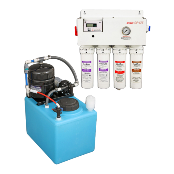
OP175 System Installation, Operation & Maintenance Getting To Know Your System The OP175 is an Advanced Membrane Separation System designed to purify water by removing dissolved minerals and then add back a consistent amount of a balanced blend of TDS (Total Dissolved Solids), or mineral content, in the treated water. -
Page 4: Installation Requirements
Installation Requirements This section and the next provide the water, electrical male pipe thread x 3/8” push-to-connect adapter is and space requirements for the OP175. Pay included in the installation kit. special attention to the feed-water chemistry requirements. Operating a system on water supplies... - Page 5 OP175 System Installation, Operation & Maintenance Typical Installation with Atmospheric Tank Important: Plumbing should be performed by a qualified plumber in accordance with local codes. Processor Power 120VAC, 2A Feed Water Inlet Water Quality Feed Operating Connection Monitor Pressure Water...
-
Page 6: Wall Mounting
OP175 System Installation, Operation & Maintenance Outside edge of processor bracket 9.1” 10.7” 15.2” 17.2” Tighten all screws. System Installation Wall Mounting Note: Do not install the cartridges in the processor The processor unit should always be mounted where until completing this section. Do not plug in the... -
Page 7: Equipment Dimensions
OP175 System Installation, Operation & Maintenance Equipment Dimensions IMPORTANT - ALLOW A MINIMUM OF 24” IN FRONT OF THE PROCESSOR FOR MAINTENANCE AND SERVICE. DO NOT MOUNT SYSTEM ABOVE THE CEILING OR IN A LOCATION THAT IS NOT EASILY ACCESSIBLE. WHEN THE 16 GAL. - Page 8 OP175 System Installation, Operation & Maintenance Inlet Repressurization Assy Outlet Optimized Water Inlet Tank Inlet Divert Valve- Shown in the normal positon Reject tubing connected to stem connector length if necessary. on bottom of AMS-QT15 Cartridge NOTE: When cutting the tubing use a sharp tubing...
-
Page 9: System Start-Up
OP175 System Installation, Operation & Maintenance System Start-Up from the Optimized Water Outlet on the Processor Refer to the illustration in “Typical Installation” (page to the distribution line feeding the equipment that will be using the Optimized Water. IMPORTANT: Before proceeding, position the 3. - Page 10 OP175 System Installation, Operation & Maintenance What are all those parts and what do they do? To User Equipment Sample Port FEED To Drain Storage Tank This section will give you an overview of how • The pure water stream continues through the the system works.
- Page 11 Processor and through the One-Way The Repressurization Pump Assembly that comes Check Valve (5) and out to the equipment. standard with the OP175 System includes a A Buffer Tank (18) between the pump and diaphragm pump controlled by a built-in Pressure...
- Page 12 OP175 System Installation, Operation & Maintenance OP175 Processor Components Automatic Shutoff Valve - PN: 524-20010 Red Tubing - Bypass Water “IN” Optimized Line Water Conductivity Reject Flow Control - Probe - PN: 564-02105 Pressure Gauge - Water Quality Monitor -...
- Page 13 OP175 System Installation, Operation & Maintenance Tank/RP Components Buffer Tank - PN: 340-50001 Buffer Tank Valve - PN: 520-14501 RP Pump - PN: 704-35513 Bypass Check Valve- PN: 524-01030 Tank Bracket - PN: 594-80516 Air Breather - RP Assy Outlet - PN: 300-40005 1/2”...
- Page 14 OP175 System Installation, Operation & Maintenance Routine Maintenance: Filter Change Procedure The only routine maintenance required on the 9. Check for leaks. system is periodic replacement of the carbon/ sediment pre-filters and the mineral addition cartridge. The CTO-Q10 cartridges should be...
-
Page 15: Troubleshooting
Short AMS-QT15 mem- Poor Feed Water quality, presence of Determine Feed Water quality by obtaining a water quality report from city iron, silica or non-calcium carbonate water supply utility or contact your OptiPure dealer brane life. hardness Short Pre-Filter life... - Page 16 OP175 System Installation, Operation & Maintenance How to Use Our Push-to-Connect Fittings Tubing Preparation Fitting Overview Cut tubing with a plastic tubing cutter or a Fitting Body razor knife. Make a clean, square cut. The outside of the tubing must be free of knicks and gouges.
Need help?
Do you have a question about the OP175 and is the answer not in the manual?
Questions and answers