Table of Contents
Advertisement
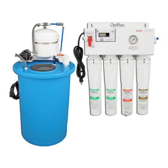
OP350
Advanced Membrane
Separation System
Installation, Operation
& Maintenance Manual
Rev. 2
Manufactured By:
OptiPure Div. of
Procam Controls, Inc.
2605 Technology Drive, Bldg. 300
Plano, TX 75074
OP350_iom-manual_v2.indd
P: 972.881.9797 F: 972.422.6262
©2015 Procam Controls, Inc. All Rights Reserved
Advertisement
Table of Contents

Related Manuals for OptiPure OP350


Summary of Contents for OptiPure OP350
- Page 1 OP350 Advanced Membrane Separation System Installation, Operation & Maintenance Manual Rev. 2 Manufactured By: OptiPure Div. of Procam Controls, Inc. 2605 Technology Drive, Bldg. 300 Plano, TX 75074 OP350_iom-manual_v2.indd P: 972.881.9797 F: 972.422.6262 ©2015 Procam Controls, Inc. All Rights Reserved...
-
Page 2: General Information
Environmental Conditions 6. Unplug the processor and RP pump from the AC outlet prior to any service. The OP350 is certified to operate under the following conditions: 7. Locate the RP Assembly as close as possible to an AC outlet. -
Page 3: Getting To Know Your System
Getting To Know Your System The OP350 Advanced Membrane Separation System is designed to purify feed water and remove dissolved minerals, and then add back a consistent amount of a balanced blend of TDS (Total Dissolved Solids), or mineral content, in the treated water, providing an Optimized Water to your equipment with the characteristics that you desire. -
Page 4: Installation Requirements
OP350 System Installation, Operation & Maintenance Installation Requirements This section and the next provide the water, electrical male pipe thread x 3/8” push-to-connect adapter is and space requirements for the OP350. Pay included in the installation kit. special attention to the feed-water chemistry Drain requirements. -
Page 5: Equipment Dimensions
OP350 System Installation, Operation & Maintenance Equipment Dimensions IMPORTANT - ALLOW A MINIMUM OF 24” IN FRONT OF THE PRO- CESSOR FOR MAINTENANCE AND SERVICE. DO NOT MOUNT SYSTEM ABOVE THE CEILING OR IN A LOCATION THAT IS NOT EAS- ILY ACCESSIBLE. - Page 6 OP350 System Installation, Operation & Maintenance Typical Installation with 50 Gal. Atmospheric Tank Important: Plumbing should be performed by a qualified plumber in accordance with local codes. Tank Processor Water Quality Repressurization Emergency Power Cord Monitor Power Return Bypass Valve...
-
Page 7: System Installation
Installation with 16 Gal. Storage Tank Mount the Optional Post-Treatment unit to the wall Refer also to “Typical Installation” Diagram on previous page. near the OP350 Processor. This unit will be plumbed- in between the Processor and the Equipment. Tighten all screws. -
Page 8: System Start-Up
OP350 System Installation, Operation & Maintenance Repressur- Install QT Cartridges ization Assy Outlet NOTE: Before installing the QT Cartridges make sure to remove the plugs in the QT heads. Tank Inlet Divert Valve- 1. Insert the CTO-Q cartridges into QT heads 1 & 2... -
Page 9: Complete The Installation
OP350 System Installation, Operation & Maintenance • Lower the float allowing the ball to drop back the water level in the storage tank to drop down. The water should begin flowing again. below the bottom of the RP Pump suction tube near the bottom of the tank. - Page 10 OP350 System Installation, Operation & Maintenance What are all those parts and what do they do? Sample FEED Port WATER ONLY! INLET To User Equipment Drain Storage Tank This section will give you an overview of how • The water flows to the inlet of the membrane the system works.
- Page 11 Repressurization Pump is equipped with a The Repressurization Pump Assembly that comes pressure switch so that when the pressure standard with the OP350 System includes a in the Buffer Tank drops, the Pump runs to diaphragm pump controlled by a built-in Pressure...
- Page 12 OP350 System Installation, Operation & Maintenance OP350 Processor Components Blue Tubing - Permeate Solenoid Valve - Optimized Water Check Valve - PN: 714-10005 “IN” Optimized Line PN: 524-01030 Water Conductivity Red Tubing - Green Tubing - Probe - Bypass Water Line Filtered Water Line “OUT”...
- Page 13 OP350 System Installation, Operation & Maintenance Tank/RP Components 50 Gallon Storage Tank Shown. Buffer Tank - Assy with 16G Storage Tank - PN: 340-50001 Assy with 50G Storage Tank - PN: 340-50004 Buffer Tank Valve - PN: 520-14501 RP Pump -...
- Page 14 (reject) carried away to the drain. the impurities rejected by the membrane. It is critical The OptiPure OP350 is designed to produce water at that both the Product Flow Rate and the Reject Flow a 30% recovery rate which means it uses water at a...
-
Page 15: Operating Parameters
OP350 System Installation, Operation & Maintenance Operating Parameters Ratio Oper Product/ Temp PRODUCT FLOW RATE REJECT FLOW RATE Reject (°F) (gal/day) (gpm) (L/day) (lpm) (gal/day) (gpm) (L/day) (lpm) 0.13 0.49 0.19 1027 0.71 0.24 1325 0.92 0.48 2650 1.84 0.26 1440 1.00... - Page 16 OP350 System Installation, Operation & Maintenance Routine Maintenance: Filter Change Procedure Optional Post-Treatment The only routine maintenance required on the system is periodic replacement of the carbon/ Cartridge Change Procedure sediment pre-filters and the mineral addition cartridge. The CTO-Q cartridges should be 1.
-
Page 17: Troubleshooting
Poor Feed Water quality, presence of Determine Feed Water quality by obtaining a water quality report from city iron, silica or non-calcium carbonate water supply utility or contact your OptiPure dealer hardness Short Pre-Filter life Heavy sediment loading Add FXAF01-12 or -12B for added Pre-Filter protection... - Page 18 OP350 System Installation, Operation & Maintenance How to Use Our Push-to-Connect Fittings Tubing Preparation Fitting Overview Cut tubing with a plastic tubing cutter or a Fitting Body razor knife. Make a clean, square cut. The outside of the tubing must be free of knicks and gouges.
Need help?
Do you have a question about the OP350 and is the answer not in the manual?
Questions and answers