Rice Lake 520 Installation Manual
Digital weight indicator
Hide thumbs
Also See for 520:
- Installation and configuration manual (16 pages) ,
- Installation manual (96 pages) ,
- Installation instructions (2 pages)
Table of Contents
Advertisement
Advertisement
Table of Contents

Related Manuals for Rice Lake 520


Summary of Contents for Rice Lake 520
- Page 1 Digital Weight Indicator Version 1.0 Installation Manual 68973...
-
Page 2: Table Of Contents
Course descriptions and dates can be viewed at www.rlws.com or obtained by calling 715-234-9171 and asking for the training department. Copyright © 2002 Rice Lake Weighing Systems. All rights reserved. Printed in the United States of America. Specifications subject to change without notice. - Page 3 Weightronix WI 120 Indicator ............73 520 Installation Manual...
- Page 4 13.14 Specifications ..............81 520 Limited Warranty..........................82...
- Page 5 520 Installation Manual...
-
Page 6: About This Manual
The Operator Card included with this manual page 14 for information about configuration methods. provides basic operating instructions for users of the 520. Please leave the Operator Card with the indicator when installation and configuration are complete. Introduction Operating Modes... -
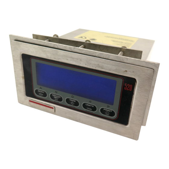
Page 7: Front Panel Display
SAMPLE Figure 1-1. 520 Front Panel Front Panel Display Figure 1-1 shows the 520 front panel keys and the key The 16-digit secondary display is used to display the weighing mode (Gross/Brutto or Net), status functions assigned in normal mode. -
Page 8: Toggle Units
UP/DOWN 1.3.2 Toggle Units To change the setpoint value, use the keys Press the key to switch between primary and to increment/decrement the decimal value of the UNITS ENTER secondary units. The units identifier is shown to the flashing digit. Press to sequence to the LEFT/RIGHT right of the primary display. -
Page 9: Set Date
The annunciator at the right side of the LCD display reads piece count (PC). Pressing the PRINT key sends the CFMT print format data string to the serial port. 520 Installation Manual... - Page 10 The following front panel entry modes will NOTE: timeout after 10 seconds if there is no activity: setpoint, time and date, and checkweigh value changes from weigh mode (press and hold the UNITS key), accumulator display (press and hold the G/N key), keyed tare display (press and hold the TARE key), and password entry.
-
Page 11: Installation
Use a wrist strap to ground yourself and protect 2.2.1 Panel Mount Disassembly components from electrostatic discharge (ESD) To remove the enclosure cover of the 520 panel mount when working inside the indicator enclosure. indicator, loosen and remove four Phillips head screws •... -
Page 12: Load Cells
For 6-wire load cell connections, remove jumpers JP1 and JP2. Table 2-1. J6 Pin Assignments ANALOG TEST GND1 TEST –5V TEST +3.3V GND1 GND2 RICE LAKE WEIGHING SYSTEMS SETUP Figure 2-1. 520 CPU and Power Supply Board, Version 2.1 Installation... -
Page 13: Serial Communications
Figure 2-4 on page 12 and plug 250 mA when active. Digital outputs are wired to the module input into connector J2 on the 520 board. switch relays when the digital output is active (low, 0 Connect the output cable to the analog output module VDC) with reference to a 5 VDC supply. -
Page 14: Cpu Board Removal
CPU Board Removal Battery Replacement If you must remove the 520 CPU board, use the The lithium battery on the CPU board maintains the following procedure: real-time clock and protects data stored in the system RAM when the indicator is not connected to AC 1. -
Page 15: Replacement Parts
Replacement Parts Table 2-5 lists replacement parts for the 520, including all parts referenced in Figures 2-2 through 2-4. Number Description (Quantity) Figure 68719 Gasket, Faceplate Figure 2-2 on page 11. 68718 Overlay, Membrane switch 68717 Shroud, Painted 68716 Faceplate, WLDT... - Page 16 10/4X 15/C 16/3X/D 11/4X 14/3X/F 24/4X FROM SWITCH MEMBRANE TO VFD DISPLAY BOARD Figure 2-2. Panel Mount Assembly Installation...
- Page 17 Figure 2-3. VFD Board MODE SELECT JUMPER Figure 2-4. Option Board Installation 520 Installation Manual...
- Page 18 (7.29) (2.75) (6.22) Figure 2-5. 520 Wire Seal 7.36 6.50 Outside perimeter of exterior faceplate (solid line) Cutout in panel (dashed line) 3.88 2.84 Outline of interior housing (dotted line) Figure 2-6. 520 Panel Mount Cut Out Template Installation...
-
Page 19: Configuration
Configuration Methods Figure 3-1. Sample Revolution Configuration Display The 520 indicator can be configured by using the front 3.1.2 EDP Command Configuration p a n e l k e y s t o n a v i g a t e t h r o u g h a s e r i e s o f The EDP command set can be used to configure the... -
Page 20: Front Panel Configuration
3.1.3 Front Panel Configuration The 520 indicator can be configured using a series of menus accessed through the indicator front panel when the indicator is in setup mode. Table 3-1 summarizes the functions of each of the main menus. Menu... -
Page 21: Menu Structures And Parameter Descriptions
Menu Structures and Parameter Descriptions The following sections provide graphic representations of the 520 menu structures. In the actual menu structure, the settings you choose under each parameter are arranged horizontally. To save page space, menu choices are shown in vertical columns. -
Page 22: Configuration Menu
3.2.1 Configuration Menu CONFIG FORMAT CALIBR SERIAL PROGRM PFORMT SETPNTS DIG IN ALGOUT VERS XXXXXXX XXXXXXX XXXXXXX XXXXXXX GRADS ZTRKBND ZRANGE MOTBAND OVRLOAD SMPRAT 1.9% FS+2% 10000 15HZ number 0.5D 100% FS+1D 30HZ FS+9D 60HZ 120HZ 7.5HZ DIGFLTR 1 DIGFLTR 2 RATTRAP DFSENS 8OUT... - Page 23 DFSENS 8OUT Digital filter cutout sensitivity. Specifies the number of consecutive readings that must fall 16OUT outside the filter threshold (DFTHRH parameter) before digital filtering is suspended. 32OUT 64OUT 128OUT 2OUT 4OUT Table 3-2. Configuration Menu Parameters 520 Installation Manual...
-
Page 24: Format Menu
CONFIG Menu Parameter Choices Description DFTHRH Digital filter cutout threshold. Specifies the filter threshold, in display divisions. When a 10DD specified number of consecutive scale readings (DFSENS parameter) fall outside of this 20DD threshold, digital filtering is suspended. If NONE is selected, the filter is always enabled. 50DD 100DD 200DD... - Page 25 Specifies primary units for displayed and printed weight. Values are: LB=pound; KG=kilogram; G=gram; OZ=ounce; TN=short ton; T=metric ton; GN=grain; LT=long ton. 230 VAC indicators are configured with KG for both primary and secondary units. NOTE: NONE Table 3-3. Format Menu Parameters 520 Installation Manual...
- Page 26 FORMAT Menu Parameter Choices Description Secondary Units (SECNDR Parameter) DECPNT 888888.8 Decimal point location. Determines the location of the decimal point or dummy zeros in the 8888888 display. 8888880 8888800 8.888888 88.88888 888.8888 8888.888 88888.88 DSPDIV Display divisions. Selects the value of minimum division size of the displayed weight. UNITS Specifies primary units for displayed and printed weight.
-
Page 27: Calibration Menu
Same as PT-> 1 Display and edit test weight value Enter mV If MVCALIB = ON (PROGRM Menu) CAL* Display and edit linear point calibration A/D count value Figure 3-7. Calibration Menu 520 Installation Manual... - Page 28 CALIBR Menu Parameter Choices Description Level 2 submenus LATITUD Press ENTER to display and edit the latitude for gravity adjustment to calibration. 0-90 ELEVATN +0345 Press ENTER to display and edit the elevation for gravity adjustment to calibration. -9999 – +9999 WZERO —...
-
Page 29: Serial Menu
3.2.4 Serial Menu See Section 13.6 on page 68 for information about 520 serial data formats. CONFIG FORMAT XXXXXXX CALIBR SERIAL PROGRM XXXXXXX SETPNTS XXXXXXX DIG IN XXXXXXX ALGOUT VERS PFORMT PRNDEST BAUD BITS TERMIN EOLDLY BAUD BITS TERMIN EOLDLY... - Page 30 SERIAL Menu Parameter Choices Description Level 3 Submenus EDP Port BAUD 9600 Baud rate. Selects the transmission speed for the EDP port. 19200 1200 2400 4800 BITS 8NONE Selects number of data bits and parity of data transmitted from the EDP port. 7EVEN 7ODD TERMIN...
- Page 31 STREAM Specifies whether data is streamed from the printer port and the configuration. LFT - Legal For Trade - streams the displayed weight IND - streams the current A/D converted weight Table 3-5. Serial Menu Parameters (Continued) 520 Installation Manual...
-
Page 32: Program Menu
3.2.5 Program Menu CONFIG FORMAT CALIBR SERIAL PROGRM PFORMT SETPNTS DIG IN XXXXXXX ALGOUT VERS DATE TIME CONSNUM DATEFMT DATESEP DATESET TIMEFMT TIMESEP TIMESET 0000000 1-9999999 MMDDYY SLASH NUMBER 12HOUR COLON NUMBER DDMMYY DASH 24HOUR COMMA YYMMDD SEMI CONSTUP ACCUM CKWEIGH 0000000 1-9999999... - Page 33 Specify prompts for use in setpoint names (up to 16 characters). Prompts are referenced by PRMPT8 the NAME parameter under the SETPTS submenus; prompts appear in the secondary display area during setpoint execution for batch type setpoints. Table 3-6. Program Menu Parameters 520 Installation Manual...
- Page 34 PROGRM Menu Parameter Choices Description REGULAT NTEP Regulatory mode. Specifies the regulatory agency having jurisdiction over the scale site. CANADA • OIML, NTEP, and CANADA modes allow a tare to be acquired at any weight greater than NONE zero. NONE allows tares to be acquired at any weight value. OIML •...
-
Page 35: Print Format Menu
Scroll left in format string Scroll right in format string characters of format Display and edit active character and Decrement ASCII value of active character Increment ASCII value of active character ASCII value Delete active character Figure 3-10. Print Format Menu 520 Installation Manual... -
Page 36: Setpoints Menu
3.2.7 Setpoints Menu See Section 12.0 on page 59 for more information about configuring and using setpoints. CONFIG FORMAT CALIBR SERIAL PROGRM PFORMT SETPTS DIG IN XXXXXXX ALGOUT VERS SP CFG BATCHNG SETPT1 SETPT2 – SETPT8 AUTO MANUAL Same as SETPT1 GROSSSP NETSP RELSP... - Page 37 Figure 3-14. Submenu for COUNTER, AUTOJOG, COZ, INMOTON, INRANGE, –GROSS, –NET, and BATCHPR Setpoints TIMER and CONCUR Setpoints START VALUE ACCESS NAME DIGOUT number 1–8 1–8 NONE NONE 1–8 1–4 HIDE Figure 3-15. Submenu for TIMER and CONCUR Setpoints 520 Installation Manual...
- Page 38 SETPTS Menu Parameter Choices Description Level 2 submenus SETPT1–SETPT8 Specifies the setpoint kind. GROSSSP GROSSSP, NETSP, +RELSP, –RELSP, and %RELSP setpoint kinds can be used as NETSP either batch or continuous setpoints. +RELSP –RELSP PAUSE, DELAY, WAITSS, COUNTER, and AUTOJOG setpoint kinds can only be %RELSP used in batch sequences.
-
Page 39: Digital Input Menu
(PROGRM menu). • GROSS, NET, PRIM, and SEC select gross, net, primary units, or secondary units display PRIM modes. • CLRTAR clears the current tare. CLRTAR • CLRACC clears the accumulator. CLRACC Table 3-8. Digital Input Menu Parameters 520 Installation Manual... -
Page 40: Analog Output Menu
3.2.9 Analog Output Menu The ALGOUT menu is used only if the analog output option is installed. If the analog output option is installed, configure all other indicator functions and calibrate the indicator before configuring the analog output. See Section 13.12 on page 78 for analog output calibration procedures. CONFIG XXXXXXX FORMAT... -
Page 41: Calibration
Calibration ™ The 520 can be calibrated using the front panel, EDP commands, or the Revolution configuration utility. Each method consists of the following steps: • Zero calibration • Entering the test weight value • Span calibration • Optional five-point linearization •... -
Page 42: Front Panel Calibration
Front Panel Calibration Use the procedure shown in Figure 4-2 to enter the actual test weight value, then press To calibrate the indicator using the front panel, do the to calibrate. The indicator displays ENTER following: *CAL* while calibration is in progress. When 1. -
Page 43: Edp Command Calibration
9. When span calibration is complete, a dialog box asks whether you wish to perform linear calibration. Click to perform linear calibration for up to five linearization points, or click to continue calibration with step 11. Figure 4-3. Revolution Calibration Display 520 Installation Manual... -
Page 44: More About Calibration
4.4.2 Gravity Adjustment to Calibration 10. On the Linear Calibration display, select the point (1–5) to calibrate, then click Calibrate This feature is used to compensate for the variance in Place test weights on scale then click gravitational pull from one location to another. When prompted, enter the test weight value To use gravity adjustment, the GRAVADJ parameter then press Enter. -
Page 45: Using Revolution
. Click . Enter NOTE: You must install Revolution version 2.7 or www.rlws.com Distributor Site your username and password to enter the later to configure the 520 indicator. Distributor Site. Click Software Downloads and then the hot link. Click the Revolution... -
Page 46: New Configuration File
file for download to the indicator. 2. Click the Create Configuration File button. 2. If the file is an already existing configuration 3. Choose the 520 file type to give the new file file, click the menu and choose File Save the appropriate .520 file extension. -
Page 47: Counting Operations
Counting Operations Sample Acquisition Mode The 520 provides a piece count mode that allows the indicator to serve as a portable counting scale. In Sample acquisition mode is used to select the sample piece count mode, the indicator display shows the... -
Page 48: Checkweigh Mode
Checkweigh Mode The 520 provides a checkweigh mode that can be The ABSOLUTE mode can be used to check weight enabled for either absolute values (ABS) or percent in either the gross or net mode. However, for values (PERCENT). ABSOLUTE mode allows you to checkweighing around zero (negative under value), enter actual weight values for over and under. -
Page 49: Peak Hold Mode
As above, the peak cycle is reset by pressing the ZERO key after the weight has been PRINT removed. 520 Installation Manual... -
Page 50: Display Accumulator
Display Accumulator The accumulator must be enabled before use in either normal mode or setpoint operations. Once enabled, weight (net weight if a tare is in the system) is accumulated whenever a print operation is performed using the PRINT key, digital input, or serial command. The scale must return to zero (net zero if a tare is in the system) before the next accumulation. -
Page 51: Edp Commands
10.0 EDP Commands The 520 indicator can be controlled by a personal Command Function computer or terminal connected to the indicator EDP KSEC Go to secondary units (pseudo key). port. Control is provided by a set of EDP commands that can simulate front panel key press functions, KPRINT In weighing mode, press the PRINT key. -
Page 52: Reporting Commands
All load cell calibration settings are lost when NOTE: VERSION the RESETCONFIGURATION command is run. Write 520 software version Write current displayed weight with units identifier. See Section 13.4 on page 66 for more information. Write one frame of stream format Table 10-2. - Page 53 OFF, LFT, IND EDP.FORMAT EDP port stream format DEFAULT8, CUSTOM, BUS FMT, DEFAULT7 PRN.BAUD Printer port baud rate 300, 600, 1200, 2400, 4800, 9600, 19200 PRN.BITS Printer port data bits/parity 8NONE, 7EVEN, 7ODD Table 10-6. SERIAL EDP Commands 520 Installation Manual...
- Page 54 Command Description Values PRN.TERMIN Printer port termination character CR/LF, CR PRN.EOLDLY Printer port end-of-line delay 0–255 (0.1-second intervals) PRN.HANDSHK Printer port handshaking OFF, ON PRN.STREAM Printer port streaming OFF, LFT, IND PRN.FORMAT Printer port stream format DEFAULT8, CUSTOM, BUS FMT, DEFAULT7 PRNDEST Print destination EDP, PRN, BOTH...
- Page 55 (view only). LAT.LOC Enter the latitude value at your current location (will be changed to match the latitude at the operating site if different than the latitude at the initial calibration site) Table 10-7. PROGRM EDP Commands (Continued) 520 Installation Manual...
- Page 56 Command Description Values SETPOINT Setpoint number 1–8 KIND Setpoint kind OFF, GROSSSP, NETSP, +RELSP, –RELSP, %RELSP, PAUSE, DELAY, WAITSS, COUNTER, AUTOJOG, COZ, INMOTON, INRANGE, –GROSS, –NET, BATCHPR, TIMER, CONCUR VALUE Setpoint value number PSHTARE Push tare OFF, ON PSHPRINT Push print OFF, ON, WAITSS PSHACCM Push accumulate...
- Page 57 GROSS, NET OFFSET Zero offset 0%, 20% ERRACT Error action FULLSC, HOLD, ZEROSC Minimum value tracked 0–9 999 999 Maximum value tracked 0–9 999 999 ZERO1 Zero calibration 0–99999 SPAN1 Span calibration 0–99999 Table 10-12. ALGOUT EDP Commands 520 Installation Manual...
-
Page 58: Normal Mode Commands
10.1.5 Normal Mode Commands The normal mode commands (see Table 10-13) transmit data to the EDP port on demand. The SX command is valid only in normal operating mode; all other commands are valid in either setup or normal mode. Command Description Response Format... -
Page 59: Batching Control Commands
DIGIN 3 Alarm @ – O Low order bits of byte 12 are set on to indicate active digital inputs setpoint alarm status. Bits are assigned as shown at right. Carriage Return (CR) Table 10-14. BATSTATUS Command Structure 520 Installation Manual... - Page 60 Translating ASCII Status Data ASCII Value Bit 3 Bit 2 Bit 1 Bit 0 Use the table at right to evaluate the ASCII character output for bytes 3 – 12 and determine which of the low order bits are set on. For example, if the Digital Output Status returned in bytes 8 –...
-
Page 61: Print Formatting
11.1 Print Formatting Commands Table 11-1 lists commands you can use to format the 520 print formats. Commands included in the format strings must be enclosed between < and > delimiters. Any characters outside of the delimiters are printed as text on the ticket. -
Page 62: Default Ticket Formats
11.2 Default Ticket Formats Table 11-2 shows the default print formats for the 520 and lists the conditions under which each print format is used. The HDRFMT format is used to specify header information that can be used by the other ticket formats. -
Page 63: Customizing Print Formats
With a personal computer, terminal, or remote format strings by changing the decimal values of the keyboard attached to the 520 EDP port, you can use ASCII characters in the format string. the EDP command set to customize the print format... -
Page 64: Setpoints
A/D update. If the input channel weight reading matches the setpoint value, the indicator sets the corresponding digital output on. are active one at a time, in an ordered sequence. The 520 can use batch setpoints to control Batch setpoints up to eight separate batch processing steps. - Page 65 START and END parameters are used to specify the start and end setpoints. If the END setpoint is not reached before the timer expires, the digital output associated with this setpoint is activated. Table 12-1. Setpoint Kinds 520 Installation Manual...
- Page 66 Kind Description Batch Continuous CONCUR Allows a digital output to remain active over a specified portion of the batch √ sequence. Two types of concur setpoints can be configured: The digital output associated with this setpoint becomes Type 1 (VALUE=0): active when the START setpoint becomes the current batch step and remains active until the END setpoint becomes the current batch step.
- Page 67 PRE CNT is PREACT LEARN interval. For setpoints set to LEARN or FLOW, PRE CNT specifies the number of batches after which PREACT is recalculated. Default value of 1 specifies that PREACT will be recalculated after every batch cycle. Table 12-2. Setpoint Menu Parameters (Continued) 520 Installation Manual...
- Page 68 SETPTS Menu Parameter Choices Description RELNUM 1–8 RELSP setpoints: Specifies the number of the relative setpoint. The target weight for this setpoint is: • For +RELSP, the value of the relative setpoint plus the value (VALUE parameter) of this setpoint •...
-
Page 69: Batching Switch
WHITE ABORT START 9 GND 10 +5V EMERGENCY STOP on 520 CPU Board STOP/START MUSHROOM SWITCH Figure 12-3. Batching Switch Wiring Diagram IN-STOP OUT-RUN To begin a batch process, turn the 3-way switch to Figure 12-2. Batching Switch momentarily. If the STOP button is pushed... -
Page 70: Appendix
13.1 Error Messages The 520 indicator provides a number of error messages. When an error occurs, the message is shown on the indicator display. Error conditions can also be checked remotely by using the XE EDP command as described in Section 13.3 on page 66. -
Page 71: Using The Hardware Command
The XE EDP command can be used to remotely query 13.4 Status Messages the 520 for the error conditions shown on the front panel. The XE command returns a decimal number Two EDP commands, P and ZZ, can be used to representing any existing error conditions. -
Page 72: Tare And Zero Key Functions
13.5 TARE and ZERO Key Functions The function of the front panel TARE and ZERO keys depends on the value specified for the REGULAT parameter on the PROGRM menu. Table 13-4 describes the function of these keys for each of the regulatory modes. -
Page 73: Data Formats
If the initiating device address matches the port If continuous transmission is configured for the EDP address of a 520 on the RS-485 network, that indicator or printer port (STREAM parameter on the SERIAL responds. For example, with demand outputs, or in... -
Page 74: Custom Stream Formatting
13.7 Custom Stream Formatting Each port can be independently configured to stream a default frame format or can be customized to stream a user-defined format. Custom formatting is very similar to the standard print formatting described in Section 12.0. Table 13-5 on page 69 lists the format identifiers used to configure a custom print format. Format Identifier Defined By Description... - Page 75 The first digit indicates the field width in characters. Decimal point only indicates floating decimal; decimal point with following digit indicates fixed decimal with n digits to the right of the decimal. <CR> — Carriage return <LF> — Line feed Table 13-5. Custom Stream Format Identifiers (Continued) 520 Installation Manual...
-
Page 76: Stream Formatting Examples
NOTE: Identifiers must be entered beginning with the high-order bit (bit 7–bit 0) of the Toledo status word. Status Word A contains the following fields. Equivalent 520 format identifiers are shown in parentheses. Bit 7: parity (B2) Bit 6: always 0 (B0) Bit 5: always 1 (B1) Bits 3–4: display divisions (B13) -
Page 77: Cardinal 738 Indicator
<units> The Cardinal uses two-character, lower-case units identifiers. The commands to set these tokens in the 520 include: STR.PRI=lb (options: kg, g, tn, t , gr, oz, or sp), STR.SEC=kg (options: lb, g, tn, t , gr, oz, or sp). -
Page 78: Weightronix Wi 120 Indicator
<units> The Weightronix uses two-character, lower-case units identifiers. The commands to set these tokens in the 520 include: STR.PRI=lb (options: kg, g, tn, t , gr, oz, or sp), STR.SEC=kg (options: lb, g, tn, t , gr, oz, or sp). -
Page 79: Ascii Character Chart
13.9 ASCII Character Chart Use the decimal values for ASCII characters listed in Tables 13-5 and 13-6 when specifying print format strings on the 520 PFORMT menu. The actual character printed depends on the character mapping used by the output device. - Page 80 ASCII ASCII ASCII ASCII Ç á α ü í β Γ é ó π â ú ä ñ Σ à Ñ σ å ª µ τ ç º ê ¿ Φ ë Θ è ¬ Ω δ ï î ∞ ì...
-
Page 81: Digital Filtering
Reconfigure as necessary to find the lowest settling time. The DFSENS (digital filter sensitivity) effective value for the DFSENS parameter. and DFTHRH (digital filter threshold) parameters can be used to temporarily override filter averaging and improve settling time: 520 Installation Manual... -
Page 82: Conversion Factors For Secondary Units
13.11 Conversion Factors for Secondary Units The 520 has the capability to mathematically convert a Primary Unit x Multiplier Secondary Unit weight into many different types of units and instantly pounds 7000.00 grains display those results with a press of the key. -
Page 83: Analog Output Calibration
For voltage output, connect voltmeter 6. Return to normal mode. Analog output leads to pins 3 and 4 function can be verified using test weights. • For current output, connect ammeter leads to pins 1 and 2 520 Installation Manual... -
Page 84: Test Mode
F i g u r e 1 3 - 6 s h ow s t h e Te s t M e n u s t r u c t u r e ; provides a number of diagnostic functions for the 520,... - Page 85 SRAM. PRTCFG Print configuration ENTER Press and hold key to send configuration data to the serial port. This function is equivalent to using the DUMPALL EDP command. Table 13-12. Test Menu Functions 520 Installation Manual...
-
Page 86: Specifications
13.14 Specifications Digital Specifications Microcomputer Hitachi H8/3002 main processor @ Power 14.74756 MHz Digital Inputs 3 inputs, TTL or switch closure, Line Voltages 115 or 230 VAC active-low Power Consumption 160 mA @ 115 VAC Digital Outputs 4 Outputs, current limited darlington pair 80 mA @ 230 VAC with TTL pull-up, 40V withstand Fusing F1 &... -
Page 87: 520 Limited Warranty
520 Limited Warranty Rice Lake Weighing Systems (RLWS) warrants that all RLWS equipment and systems properly installed by a Distributor or Original Equipment Manufacturer (OEM) will operate per written specifications as confirmed by the Distributor/OEM and accepted by RLWS. All systems and components are warranted against defects in materials and workmanship for two years.
Need help?
Do you have a question about the 520 and is the answer not in the manual?
Questions and answers