Table of Contents
Advertisement
Quick Links
Advertisement
Table of Contents

Related Manuals for Rice Lake 590 AG


Summary of Contents for Rice Lake 590 AG
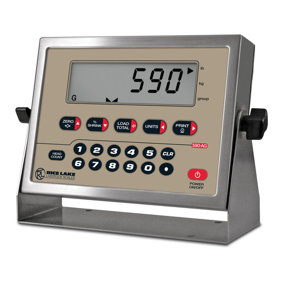
- Page 1 590 AG Animal Weigher Indicator Version 1.06 Operation Manual 154974 Rev B...
-
Page 3: Table Of Contents
Course descriptions and dates can be viewed at www.ricelake.com/training or obtained by calling 715-234-9171 and asking for the training department. © Rice Lake Weighing Systems. All rights reserved. Printed in the United States of America. Specifications subject to change without notice. - Page 4 8.8 Specifications ..............48 590 AG Indicator Limited Warranty ......................49 For More Information ..........................50 Rice Lake continually offers web-based video training on a growing selection of product-related topics at no cost. Visit www.ricelake.com/webinars. 590AG Animal Weigher Indicator Operation Manual...
-
Page 5: Introduction
• AC adapter for 115 or 230 VAC power • Configurable standby mode limits indicator power consumption when scale is inactive The 590 AG Indicator is NTEP-certified for Classes III and III L at 10,000 divisions. See Section 8.8 for detailed specifications. -
Page 6: Safety
Do not operate or work on this equipment unless you have read and understand the instructions and warnings in this manual. Failure to follow the instructions or heed the warnings could result in injury or death. Contact any Rice Lake Weighing Systems dealer for replacement manuals. Proper care is your responsibility. -
Page 7: Operating Modes
Section 1.5 to indicate scale status and the type of weight value displayed. Once configuration is complete and a legal seal is affixed to the back of the indicator, the 590 AG Indicator can operate only in normal mode. -
Page 8: Display Annunciators
Display Annunciators The 590 AG Indicator display uses a set of LCD annunciators to provide additional information about the value being displayed. Figure shows these annunciators and their meanings. Primary Displayed units Secondary group Group mode Tare - Not Available... -
Page 9: Indicator Operations
Indicator Operations Basic operations are summarized below: 1.6.1 Enter % shrink Use the numeric keypad to enter the shrink factor value, then press the % SHRINK key. The entered shrink factor is applied to every weighment until the shrink factor is changed or the indicator is reset. This value is stored in the eeprom to survive power cycles. -
Page 10: Installation
Disconnect battery cable to connector J3, then set the backplate assembly aside. Cable Connections The 590 AG Indicator provides two cord grips for cabling into the indicator: • One for the load cell cable • One for serial communications. -
Page 11: Cable Grounding
2.3.1 Cable Grounding Except for the power cord, all cables routed through the cord grips should be grounded against the indicator backplate. Do the following to ground shielded cables: • Use the lockwashers, clamps, and kep nuts provided in the parts kit to install grounding clamps on the backplate studs adjacent to cord grips. -
Page 12: Load Cells
Once cables are attached, reconnect J2 to the header on the board. The 590 AG Indicator serial port supports full duplex RS-232 communications for connections to printers, PCs, and other attached devices. See Section 3.0 for general configuration information; see Section 3.2.4 for serial port configuration. -
Page 13: Enclosure Reassembly
Input Adapter Input Figure 2-4. 590 AG Indicator CPU Board Enclosure Reassembly Once cabling is complete, position the backplate over the enclosure, reconnect battery cable, and reinstall the backplate screws. Use the torque pattern shown in Figure 2-5 to prevent distorting the backplate gasket. Torque screws to 15 in-lb (1.7 N-m). -
Page 14: Battery Installation
Battery Installation To install or replace batteries, do the following: 1. Remove the four thumbscrews that hold the battery cover to the enclosure backplate. 2. Install six alkaline C-cell batteries as shown in Figure 2-6. 3. Replace the battery cover and reinstall thumbscrews. Torque thumbscrews to 15 in-lb (1.7 N-m). Figure 2-6. -
Page 15: Ac Adapter
4. Plug AC adapter from power outlet to the indicator adapter port. Close the adapter port cover and reinstall screws as described in Section 2.4 when not using the AC adapter. The 590 AG Indicator enclosure cannot be rated for NEMA 4X/IP66 applications with the AC adapter port Important cover open. -
Page 16: Replacement Parts
Replacement Parts 1/4X 1.0 .12 29/2X 7/2X 9/2X 10/3X/A 11/3X 15/4X 39/D 13/2X 25/2X 24/2X 40/2X/C 27/4X 38/2X/B 36/8X 590AG Animal Weigher Indicator Operation Manual... - Page 17 Item # Part No. Description 49520 Battery Cover Thumb Screws 71352 " Battery Cover, 3 X 7 71354 Battery Cover Gasket 71448 Battery Holder Assembly 19538 Cable Grip Plug 42640 Setup Switch Access Screw, 1/4 X 28NF X 1/4 15626 Cable Grips, PG9 44676 Sealing washer for setup switch access screw, #14...
-
Page 18: Configuration
To use Revolution, do the following: 1. Install Revolution on an IBM-compatible personal computer. • Minimum system specifications: • 600+ MHz Intel compatible processor • 1 GB of RAM 590 AG Indicator Operators Manual... -
Page 19: Edp Command Configuration
• 20 GB free hard drive space ® • Windows XP SP3 (32-bit), Windows Vista SP2 (x86 or64), Windows 7 (x86 or x64), or Windows 8 ™ (x86 or x64) • RS-232 or TCP/IP connections to an indicator. • Recommended system specifications: •... -
Page 20: Front Panel Configuration
Front Panel Configuration The 590 AG Indicator indicator can be configured using a series of menus accessed through the indicator front panel when the indicator is in setup mode. Table 3-1 summarizes the functions of each of the main menus. - Page 21 Four front panel keys are used as directional keys to navigate through the menus in setup mode (see Figure 3-2). UNITS ( ) and PRINT ( ) keys scroll left and right (horizontally) on the same menu level; ZERO ( ) and ( ) move up and down (vertically) to different menu levels.
-
Page 22: Menu Structures And Parameter Descriptions
1.9% FS+2% 7.5HZ 10000 0.5D FS+1D 15HZ number 100% FS+9D 30HZ 3.75HZ DIGFL1 DIGFL2 DIGFL3 DFSENS DFTHRH 8OUT NONE 16OUT 32OUT 64OUT 10DD 128OUT 20DD 2OUT 50DD 4OUT 100DD 200DD 250DD Figure 3-4. Configuration Menu 590 AG Indicator Operators Manual... - Page 23 CONFIG Menu Parameter Choices Description GRADS 10000 Graduations. Specifies the number of full scale graduations. The value entered must be in number the range 1–999 999 and should be consistent with legal requirements and environmental limits on system resolution. To calculate GRADS, use the formula, GRADS = Capacity / Display Divisions. Display divisions for primary and secondary units are specified on the FORMAT menu.
-
Page 24: Format Menu
Specifies primary units for displayed and printed weight. Values are: lb = pound; kg = kilogram; OZ = ounce; TN = short ton; T = metric ton; G = gram Indicators sold outside North America are configured with kg for both primary and secondary units. NONE 590 AG Indicator Operators Manual... - Page 25 FORMAT Menu Parameter Choices Description Format submenu SECNDR DECPNT Secondary Units – Specifies the decimal position, display divisions, units, and conversion DSPDIV multiplier used for the secondary units. See below for submenu parameter descriptions. UNITS Secondary Units submenus DECPNT 88888.8 Decimal point location.
-
Page 26: Calibration Menu
Press Enter to remove an offset value from the zero and span calibrations. REZERO — Use this parameter only after WZERO and WSPAN have been set. See Section 4.1 for more information about using this parameter. Table 3-2. Calibration Menu Parameters 590 AG Indicator Operators Manual... -
Page 27: Serial Menu
3.2.4 Serial Menu See Section 8.2 for information about the 590 AG Indicator serial data format. CONFIG FORMAT CALIBR SERIAL PROGRM PFORMT VERS BAUD BITS TERMIN EOLDLY STREAM 9600 8NONE CR/LF 000000 19200 7EVEN number 7ODD INDUST 1200 2400 4800 Figure 3-7. -
Page 28: Program Menu
LSTMOD Last mode. Specifies whether the indicator resumes operation in the last mode it was in before entering standby mode (YES) or performs the standard power-up sequence (NO). Table 3-4. Program Menu Parameters 590 AG Indicator Operators Manual... - Page 29 PROGRM Menu Parameter Choices Description PROGRM menu parameters continued DSPHLD DSPMOD Specifies whether operator wants to use the display hold mode, set the hold delta percentage HDELTA and the display hold sampling time. See sub-menu parameter descriptions below. SMPTIM DSPHLD sub-menu parameters DSPMOD DSABLE Display hold mode –...
-
Page 30: Print Format Menu
The VERS menu is used to check the software version installed in the indicator. There are no parameters associated with the Version menu: when selected, the indicator displays the installed software version number. CONFIG FORMAT CALIBR SERIAL PROGRM PFORMT VERS Software version Figure 3-10. Version Menu 590 AG Indicator Operators Manual... -
Page 31: Calibration
Calibration ® The 590 AG Indicator can be calibrated using the front panel, EDP commands, or Revolution . Each method consists of the following steps: • Zero calibration • Entering the test weight value • Span calibration • Optional rezero calibration for test weights using hooks or chains. -
Page 32: Revolution Calibration
6. When calibration is complete, the fields of the indicator calibration display are filled in. Click New Settings to save the new values and return to the Revolution main menu; to restore the previous calibration Exit values, click Restore Settings 590 AG Indicator Operators Manual... -
Page 33: Edp Commands
EDP Commands The indicator can be controlled by a personal computer or remote keyboard connected to the indicator EDP port. Control is provided by a set of EDP commands that can simulate front panel key press functions, display and change setup parameters, and perform reporting functions. The EDP port provides the capability to print configuration data or to save that data to an attached personal computer. -
Page 34: Reporting Commands
DUMPALL List all parameter values 5.1.3 The RESETCONFIGURATION Command VERSION Write 590 AG Indicator software version Reset the indicator The RESETCONFIGURATION command can be used Write current displayed weight with units to restore all configuration parameters to their default identifier. - Page 35 Command Description Values PRI.DECPNT Primary units decimal position 8.88888, 88.8888, 888.888, 8888.88, 88888.8, 888888, 888880 PRI.DSPDIV Primary units display divisions 1D, 2D, 5D PRI.UNITS Primary units LB, KG, OZ, TN, T, G, NONE SEC.DECPNT Secondary units decimal position 8.88888, 88.8888, 888.888, 8888.88, 88888.8, 888888, 888880 SEC.DSPDIV Secondary units display divisions 1D, 2D, 5D...
-
Page 36: Normal Mode Commands
5.2 Saving and Transferring Data Connecting a personal computer to the 590 AG Indicator EDP port allows you to save indicator configuration data to the PC or to download configuration data from the PC to an indicator. The following sections describe the procedures for these save and transfer operations. -
Page 37: Animal Weighing Operation
Animal Weighing Operation The 590 AG Indicator provides two modes for displaying the weight of the animals on the scale. • Live mode – When Display Hold mode is disabled, indicator display always shows the current scale weight. • Hold mode – When enabled, the indicator will sample the scale for the number of seconds configured and will then display &... - Page 38 6. Another load can now be started. There is no reprint ability for the Load Total data. Pressing the Print key when not in Group Mode (group), will send the current gross weight displayed to the serial port. 590 AG Indicator Operators Manual...
-
Page 39: Print Formatting
Print Formatting The 590 AG Indicator provides three print formats, GFMT, GPFMT, and LDFMT that determine the format of the printed output when the key is pressed or when a KPRINT EDP command is received. PRINT Each print format can be customized to include up to 300 characters of information, such as company name and address, on printed tickets. -
Page 40: Customizing Print Formats
7.2.1 Using the EDP Port With a personal computer, terminal, or remote keyboard attached to the 590 AG Indicator EDP port, you can use the EDP command set to customize the print format strings. To view the current setting of a format string, type the name of the string (GFMT, GPFMT, or LDFMT) and press... -
Page 41: Using The Front Panel
Lower-case letters and some special characters cannot be displayed on the 590 AG Indicator front panel (see the ASCII character chart in Section 8.3) and are shown as blanks. The 590 AG Indicator can send or receive any ASCII character; the character printed depends on the particular ASCII character set implemented for the receiving device. -
Page 42: Using Revolution
Using Revolution, you can type text directly into the grid, then select weight value fields from the tool bar and place them where you want them to appear on the printed ticket. Figure 7-2 shows an example of the Revolution print formatting grid. Figure 7-2. Revolution Print Format Grid 590 AG Indicator Operators Manual... -
Page 43: Appendix
Appendix 8.1 Error Messages The 590 AG Indicator provides a number of front panel error messages to assist in problem diagnosis. Table 8-1 lists these messages and their meanings. Error Message Description Solution ADCERR A/D not responding Call Rice Lake Weighing Systems (RLWS) Service. -
Page 44: Ascii Character Chart
590 AG Indicator PFORMT menu. The actual character printed depends on the character mapping used by the output device. The 590 AG Indicator can send or receive any ASCII character value (decimal 0–255), but the indicator display is limited to the set described in Section 8.4 on page 42. - Page 45 ASCII ASCII ASCII ASCII Ç á ü í é ó â ú ä ñ à Ñ å ª ç º ê ¿ ë è ¬ ï î ...
-
Page 46: Front Panel Display Characters
8.4 Front Panel Display Characters Figure 8-2 shows the 7-segment LCD character set used to display alphanumeric characters on the 590 AG Indicator front panel. " < & > Figure 8-2. 590 AG Indicator Display Characters 590 AG Indicator Operators Manual... -
Page 47: Conversion Factors For Secondary Units
8.5 Conversion Factors for Secondary Units The 590 AG Indicator has the capability to mathematically convert a weight into many different types of units and instantly display those results with a press of the key. Secondary units can be specified on the FORMAT UNITS menu using the SECNDR parameter, or by using EDP commands. -
Page 48: Digital Filtering
Table 8-4. Conversion Factors 8.6 Digital Filtering The 590 AG Indicator uses averaged digital filtering to reduce the effect of vibration on weight readings. Adjustable threshold and sensitivity functions allow quick settling by suspending filter averaging, allowing the weight reading to jump to the new value. Figure 8-3 shows the digital filter parameters on the CONFIG menu. -
Page 49: Digflx Parameters
Filter Average Filter Average Filter Average Figure 8-4. Flow Diagram for 590 AG Indicator Digital Filters 8.6.1 DIGFLx Parameters The first three digital filtering parameters, DIGFL1, DIGFL2, and DIGFL3, are configurable filter stages that control the effect of a single A/D reading on the displayed weight. The value assigned to each parameter sets the number of readings received from the preceding filter stage before averaging (see Figure 8-4). -
Page 50: Test Mode
Reconfigure as necessary to find the lowest effective value for the DFSENS parameter. 8.7 Test Mode In addition to normal and setup modes, test mode provides a number of diagnostic functions for the 590 AG Indicator, including: •... - Page 51 TEST Menu Function Description A/DTST Display A/D test Press and hold Enter key to display raw count from A/D converter. ADOFFS A/D offset calibration (–0.5 mv/V) Read Important! statement below before using this function. Press and hold the setup switch, then press the Enter key to perform offset calibration.
-
Page 52: Specifications
19200, 9600, 4800, 2400, 1200, 600, 300 bps; 8 data bits, no parity, or 7 data bits, even Measurement Canada or odd parity Approval AM-5300 Accuracy Class III n : 10 000 III HDn : 20 000 590 AG Indicator Operators Manual... -
Page 53: 590 Ag Indicator Limited Warranty
590 AG Indicator Limited Warranty Rice Lake Weighing Systems (RLWS) warrants that all RLWS equipment and systems properly installed by a Distributor or Original Equipment Manufacturer (OEM) will operate per written specifications as confirmed by the Distributor/OEM and accepted by RLWS. All systems and components are warranted against defects in materials and workmanship for two years. -
Page 54: For More Information
Email • US sales and product information at • prodinfo@ricelake.com • International (non-US) sales and product information at • intlsales@ricelake.com Mailing Address Rice Lake Weighing Systems 230 West Coleman Street Rice Lake, WI 54868 USA 590 AG Indicator Operators Manual... - Page 56 230 W. Coleman St. • Rice Lake, WI 54868 • USA U.S. 800-472-6703 • Canada/Mexico 800-321-6703 • International 715-234-9171 • Europe +31 (0)26 472 1319 www.ricelake.com www.ricelake.mx www.ricelake.eu www.ricelake.co.in m.ricelake.com © Rice Lake Weighing Center 01/2015 PN 154974 Rev B...
Need help?
Do you have a question about the 590 AG and is the answer not in the manual?
Questions and answers