Table of Contents
Advertisement
Quick Links
Advertisement
Table of Contents

Related Manuals for Viega Profipress S


Summary of Contents for Viega Profipress S
- Page 1 Profipress S Instructions for Use Year built: from 01/2008 en_INT...
- Page 2 Profipress S 2 from 24...
-
Page 3: Table Of Contents
Permitted exchange of sealing elements 3.3.4 Space requirements and intervals 3.3.5 Required tools Assembly 3.4.1 Replacing the sealing element 3.4.2 Bending pipes 3.4.3 Shortening the pipes 3.4.4 Deburring the pipes 3.4.5 Pressing the connection 3.4.6 Leakage test Maintenance Disposal Profipress S 3 from 24... -
Page 4: About These Instructions For Use
This restriction does not extend to possible operating instructions. The installation of Viega products must take place in accordance with the general rules of engineering and the Viega instructions for use. -
Page 5: About This Translated Version
German/European directives specified in this manual: The information herein is not binding for other countries and regions; as said above, they should be understood as a recommendation. Profipress S 5 from 24... -
Page 6: Product Information
Test on a system that is finished DIN EN 12976-1 but not yet covered Test on a system that is finished DIN EN 12976-2 but not yet covered Test on a system that is finished DKI-Informationsdruck i.160 but not yet covered Profipress S 6 from 24... -
Page 7: Intended Use
Coordinate the use of the system in units with additives ( e. g. anti-freeze or anti-corrosion agents) in heating water or for fields of application and media other than those described with the Viega Service Center. 2.2.1 Areas of use Do not use the piping system in potable water and gas installations. -
Page 8: Pipes
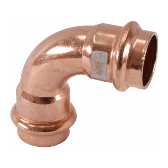
Product information Fig. 1: Profipress S press connectors The system components are available in the following dimensions: d 12 / 15 / 18 / 22 / 28 / 35. Profipress connectors can be equipped with FKM sealing elements for dimensions above 35 mm. - Page 9 2.25 35.0 2.75 Length expansion Pipelines expand with heat. Heat expansion is dependent on the mate‐ rial. Changes in length lead to tension within the installation. These ten‐ sions must be equalised with suitable measures. Profipress S 9 from 24...
- Page 10 3 - Temperature difference ⃗Δϑ [K] The length expansion Δl can be taken from the diagram or can be cal‐ culated using the following formula: Δl = ⍺ [mm/mK] × L [m] x Δϑ [K] Profipress S 10 from 24...
-
Page 11: Press Connectors
Press connectors are available in a number of shapes. An overview of the press connectors suitable for the system can be found in the cata‐ logue. The press connectors in the Profipress S system consist of the following materials: Copper Gunmetal/silicon bronze Fig. -
Page 12: Sealing Elements
Short-term peak temper‐ Comments — — atures ≤ 280 °C Consultation with the Viega Service Center required. 2.3.5 Markings on components Markings on press connectors The press connectors are marked with a coloured dot. This identifies the SC-Contur, where the test medium would escape in the case of an inadvertently unpressed connection. -
Page 13: Information For Use
Contact with aggressive building materials such as nitrite or mate‐ rials containing ammonium in aggressive surroundings If external corrosion protection is required, observe the pertinent guide‐ lines, see Ä „Regulations from section: Corrosion“ on page 6. Profipress S 13 from 24... -
Page 14: Handling
3.3.1 Mounting instructions Checking system components System components may, in some cases, become damaged through transportation and storage. Check all parts. Replace damaged components. Do not repair damaged components. Contaminated components may not be installed. Profipress S 14 from 24... -
Page 15: Potential Equalisation
The exchange of a sealing element is generally permitted. The sealing element must be exchanged for a designated spare part for the intended application Ä Chapter 2.3.4 „Sealing elements“ on page 12. The use of other sealing ele‐ ments is not permitted. Profipress S 15 from 24... -
Page 16: Space Requirements And Intervals
Exchanging a sealing element is permitted in the following situations: if the sealing element in the press connector is obviously damaged and should be exchanged for a Viega replacement sealing element made of the same material if an EPDM sealing element in Profipress connectors should be exchanged for an FKM sealing element (higher thermal resistance, e. - Page 17 Space requirement press ring a [mm] b [mm] c [mm] Distance to walls Minimum interval with d 12–35 [mm] Press machine Type 2 (PT2) Type PT3-EH Type PT3-AH Pressgun 4E / 4B Pressgun 5 Picco / Pressgun Picco Profipress S 17 from 24...
-
Page 18: Required Tools
Press jaw or press ring with corresponding hinged adapter jaw, suit‐ able for the pipe diameter and suitable profile Fig. 6: Press jaws Profipress S 18 from 24... -
Page 19: Assembly
Handling Recommended Viega press machines: Pressgun 5 Pressgun Picco Pressgun 4E / 4B Picco Type PT3-AH Type PT3-H / EH Type 2 (PT2) Assembly 3.4.1 Replacing the sealing element Removing the sealing element Do not use pointed or sharp-edged objects to remove the sealing element. -
Page 20: Bending Pipes
The pipe ends must be thoroughly deburred internally and externally after shortening. Deburring prevents the sealing element being damaged or the that the press connector cants when mounted. Use of a deburrer (model 2292.2) is recommended. Profipress S 20 from 24... - Page 21 Handling NOTICE! Damage due to the wrong tool! Do not use sanding disks or similar tools when deburring. The pipes could be damaged by these. Deburr the inside and outside of the pipe. Profipress S 21 from 24...
-
Page 22: Pressing The Connection
Push the press connector onto the pipe as far as it will go. Mark the insertion depth. Place the press jaw onto the press machine and push the retaining bolt in until it clicks into place. INFO! Observe the press tool instruction manual. Profipress S 22 from 24... -
Page 23: Leakage Test
Observe the applicable regulations, see Ä „Regulations from section: Leakage test“ on page 6. Document the result. Maintenance Observe the applicable regulations for the operation and maintenance of solar installations, see Ä „Regulations from section: Maintenance“ on page 7. Profipress S 23 from 24... -
Page 24: Disposal
Handling Disposal Separate the product and packaging materials (e. g. paper, metal, plastic or non-ferrous metals) and dispose of in accordance with valid national legal requirements. Profipress S 24 from 24...
Need help?
Do you have a question about the Profipress S and is the answer not in the manual?
Questions and answers