
Related Manuals for Atlona OmniStream R-Type


Summary of Contents for Atlona OmniStream R-Type
- Page 1 OmniStream R-Type ™ Single-Channel Networked AV Decoder Atlona Manuals AT-OMNI-521 Networked AV...
- Page 2 Version Information Version Release Date Notes 4/18 Initial release 7/18 Includes updates to 1.2.1 firmware; AMS updates AT-OMNI-521...
- Page 3 Welcome to Atlona! Thank you for purchasing this Atlona product. We hope you enjoy it and will take a extra few moments to register your new purchase. Registration only takes a few minutes and protects this product against theft or loss. In addition, you will receive notifications of product updates and firmware.
- Page 4 Atlona requires that products returned are properly packed, preferably in the original carton, for shipping. Cartons not bearing a return authorization or case number will be refused. Atlona, at its sole discretion, reserves the right to reject any products received without advanced authorization. Authorizations can be requested by calling 1-877-536-3976 (US toll free) or 1-408- 962-0515 (US/international) or via Atlona’s website at www.atlona.com.
- Page 5 Damage, deterioration or malfunction resulting from the installation or removal of this product from any installation, any unauthorized tampering with this product, any repairs attempted by anyone unauthorized by Atlona to make such repairs, or any other cause which does not relate directly to a defect in materials and/or workmanship of this product.
-
Page 6: Important Safety Information
The information bubble is intended to alert the user to helpful or optional opera- product. tional instructions in the literature accompanying the product. 11. Only use attachments/accessories specified by Atlona. 1. Read these instructions. 12. To reduce the risk of electric shock and/or damage 2. Keep these instructions. -
Page 7: Table Of Contents
Table of Contents Introduction Features Package Contents Panel Description Installation RS-232 Connections IR Connections Connection Instructions Connection Diagram Configuration Discovery using AMS Accessing Decoders in AMS Configuring a Static IP Address Basic Operation LED Indicators ID Button Broadcast Messaging Reset to Factory-Default Settings. Rebooting OmniStream Unicast Mode Multicast Mode... - Page 8 Table of Contents The Virtual Matrix Accessing the Virtual Matrix Layout and Operation Appendix Mounting Instructions Rack Tray for OmniStream Specifications AT-OMNI-521...
-
Page 9: Introduction
UHD @ 60 Hz and HDR, plus embedded audio and RS-232 or IR control pass-through. It is part of the OmniStream R-Type Series, designed for high performance, flexible distribution of AV over Gigabit Ethernet in residential and commercial applications. The OmniStream 521 is HDCP 2.2 compliant and ideal for the latest as well as emerging UHD and HDR displays. -
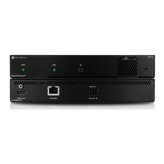
Page 10: Panel Description
Panel Description LINK LINK TREAM Front TREAM RX TX RX TX HDMI OUT ETHERNET RS-232 / IR AT-OMNI-521 HDMI OUT ETHERNET RS-232 / IR AT-OMNI-521 Rear HDMI OUT This LED indicator glows bright green when the unit Connect an HDMI cable from this port to a UHD/HD is powered. -
Page 11: Installation
Installation RS-232 Connections The AT-OMNI-521 provides RS-232 over IP which allows communication between an automation system and an RS- 232 device. This step is optional. Either the top three or bottom three set of terminals can be used for RS-232. 1. -
Page 12: Ir Connections
Unit GND (black) SIGNAL (white/black) TX out The following components are required. Note that other components may also be used. However, Atlona has tested and verified the following components for this application: • Xantech CB12 1 Zone Connecting Block •... - Page 13 Installation For downstream IR control, either multicast or unicast mode can be used. However, when controlling a source from the decoder (viewing location), unicast mode should be used. Refer to Unicast Mode (page 22) Multicast Mode (page 24) for more information. Refer to IR Control (page 28) for information on IR configuration within AMS.
-
Page 14: Connection Instructions
Installation Connection Instructions 1. Connect an Ethernet cable from the ETHERNET port on the decoder to a PoE-capable switch on the Local Area Network (LAN). IMPORTANT: If a PoE-capable switch is not available, a PoE injector (purchased separately) must be used. 2. -
Page 15: Connection Diagram
Installation Connection Diagram Blu-ray Player Automation Control System CT OR RE SE 48 V M NI AT-OMNI-512 Projector AT-OMNI-521 M NI AT-OMNI-521... -
Page 16: Configuration
By default, the AT-OMNI-521 is set to DHCP mode, allowing a DHCP server (if present) to assign the decoder an IP address. Once an IP address has been assigned, the Atlona Management System (AMS) can be used to manage the product on the network. - Page 17 Configuration 6. Click Devices from the fly-out menu. 7. Click the Unassigned option. All available OmniStream decoders will be displayed under the Unassigned category. When a device is unassigned, it means that the device has not yet been assigned to a site, building, and/or room. Refer to the AMS User Manual for more information on these topics.
- Page 18 Configuration 8. Click the desired AT-OMNI-521 from the Unassigned device list. Once the unit is selected, the control interface for the AT-OMNI-521 will be displayed. AT-OMNI-521...
-
Page 19: Configuring A Static Ip Address
Configuration Configuring a Static IP Address The following section is only required to set the AT-OMNI-521 decoder, currently in Auto IP mode, to a static IP address. If a DHCP server is not found within 60 seconds, decoders are automatically placed in Auto IP mode and will be assigned an IP address within the range 169.254.xxx.xxx. -
Page 20: Basic Operation
Basic Operation LED Indicators The following table provides a listing of front-panel LED indicators and their status: Description Unit is powered off. • If using a PoE switch, make sure that the port on the switch that is connected to the decoder, has PoE enabled. When the decoder is powered using PoE, the PWR indicator will be green. -
Page 21: Id Button
Basic Operation ID Button The ID button serves two functions: 1. Sends a broadcast message, over the network, to any devices that may be listening. 2. Resets the decoder to factory-default settings. LINK TREAM RX TX Broadcast Messaging Press and release the ID button to send a broadcast notification over the network to any devices that may be listening. -
Page 22: Unicast Mode
Accessing Decoders in AMS (page 16) if necessary. 2. Go to the encoder AMS interface. Refer to the OmniStream R-Type A/V Encoder User Manual, if necessary. 3. Click SESSION in the menu bar and scroll down to the Video section. - Page 23 Basic Operation 5. Go to the decoder AMS interface. 6. Click IP INPUT from the menu. 7. Remove the IP address from the Multicast Address field. 8. Click the SAVE button to commit changes. Field should be blank 9. Unicast setup is complete. The decoder unit will now receive streams exclusively from the encoder containing the IP address of this decoder.
-
Page 24: Multicast Mode
Basic Operation Multicast Mode The term multicast is used to describe a configuration where information is sent from one or more points to a set of other points. For example, a single encoder can transmit data to multiple decoders. In addition, if multiple encoders are used, each encoder can stream data to any decoder that is not already receiving data from an encoder. - Page 25 Basic Operation AT-OMNI-521...
-
Page 26: Aes67 Audio
AMS Dashboard. 4. Click Devices > All and select the desired encoder from the Device List. 5. Go to the encoder interface and click SESSION in the menu bar. Refer to the OmniStream R-Type A/V Encoder User Manual, if necessary. - Page 27 Basic Operation 7. Select the type of downmixing from the Downmixing drop-down list, if desired. Available options are: None, Stereo, or Mono. 8. Click the SAVE button within the Session section. 9. Go to the decoder interface and click SAP from the menu bar, at the top of the screen. Under the SAP section, click the Enable toggle switch and enable SAP.
-
Page 28: Ir Control
Basic Operation IR Control OmniStream provides IR control from either the headend / source location to the displays (downstream) or from the viewing location to the headend (upstream). For downstream IR control, either multicast or unicast mode can be used. However, when controlling a source from the viewing location, unicast mode should be used. Refer to Unicast Mode (page 22) Multicast Mode (page 24) - Page 29 Basic Operation 7. Scroll down and locate the Serial Configuration 2 section. 8. Click the Port drop-down list and select serial_port2. 9. Click the Mode drop-down list and select Output. 10. Click the Input drop-down list and select the IP input. The selected input must not be currently in use by another session.
-
Page 30: Upstream Ir Control
Basic Operation Upstream IR Control In order to send IR data upstream, from the decoder to the encoder, a few additional simple steps are required. 1. Follow steps 1 through 10, under Downstream IR Control (page 28). 2. Enter the IP address, in the Destination IP Address field, where the IR data will be sent. 3. -
Page 31: Descrambling
Basic Operation Descrambling OmniStream supports 128-bit Advanced Encryption Standard (AES) scrambling for both audio and video streams. Descrambling can be enabled or disabled through AMS (before or after the decoding process has started), and can be individually applied to video, audio, or both. Data streams cannot be descrambled; only video and audio can be scrambled. -
Page 32: Using The Virtual Matrix
Basic Operation 3. Enter the desired scrambling key in the Key field. NOTE: If a user-defined key is specified, then it must be a minimum of eight alphanumeric characters. Special characters and spaces are not permitted. 4. Click the Save button at the bottom of the page to commit the changes. Using the Virtual Matrix 1. - Page 33 Basic Operation 5. Enter the desired scrambling key using one of the following methods: • Manual enter a user-defined key in the Key field. • Click the icon to generate a random key using AMS. Each time this icon is clicked, a new scrambling key will be generated.
-
Page 34: Slate / Logo Insertion
(decoder) will be from the encoder IP address(es) to which each decoder is subscribed. When configuring on the decoder, the presence of the image is specified on the (individual) HDMI output. Refer to the OmniStream R-Type A/V Encoder User Manual, for information on managing slate / logo insertion on encoder units. -
Page 35: Deleting Slates / Logos
Basic Operation NOTE: If the selected image will be used as a logo, then proceed with Steps 7 through 9. If the image will be used as a slate, skip to Step 10. 7. Click the logo from the Select Logo drop-down list. To prevent the image from being displayed, select the Not used option. -
Page 36: Text Insertion
Basic Operation Text Insertion Text can be inserted and scrolled across the screen, making it useful for messages and notifications. Several options are available when using text: Scroll speed adjustment (forward, reverse, or static), number of iterations, text color, vertical / horizontal position, as well as transparency. 1. - Page 37 Basic Operation 9. Specify the size of the text in the Width (%) and Height (%) fields. Each of these values is based on the horizontal and vertical resolution of the screen. 10. Click the SAVE button to apply all changes. AT-OMNI-521...
-
Page 38: Creating Video Walls
Basic Operation Creating Video Walls The following example illustrates how to configure a 2x2 video wall. Below, four decoders are subscribed to a single encoder. The decoder is displaying the same image on all four displays. The video source is 3840 x 2160. In order to create a single image using all four displays, each source image will need to be cropped and scaled to one-fourth of the total image resolution. - Page 39 Basic Operation 3. Locate the Resolution option and select 1920x1080. This will scale the output resolution from each decoder to 1920x1080. 4. Click the Stretch/Crop Mode drop-down list and select Full Screen. This guarantees that the image will fill the screen.
- Page 40 Basic Operation 5. Click the Enable toggle to activate the Video wall option. Once enabled, the Video wall section will be expanded and display all available options. 6. Enter the horizontal and vertical resolution of the display in the Width and Height fields. This is the size of the source to be used for this window of the video wall.
- Page 41 Basic Operation 8. Enter the horizontal and vertical resolution of the display in the Width and Height fields. This is the size of the source to be used for this window of the video wall. The table below, lists width and height examples for a 2x2 video wall, with the specified source resolution.
- Page 42 Basic Operation The image on Display 1 has been cropped and rotated and now is displayed correctly. 11. Click the SAVE button at the bottom of the screen to accept changes. 12. Repeat steps 1 through 9 for decoders 2, 3, and 4. Note that in this example, at Step 10, decoders 3 and 4 will not require any rotation.
- Page 43 Basic Operation Once all four decoders have been properly configured, the video wall should appear similar to the following: Encoder Decoder AV LAN Decoder Decoder Decoder Display Wall 13. Check the image, on each display, and make sure they are aligned correctly with the other images on the video wall.
-
Page 44: Bezel Compensation
Bezel compensation can be adjusted at any time. The illustration on the left shows a simple 2x2 video wall without bezel compensation. Note how the Atlona logo is stretched, horizontally. On the right, bezel compensation is used to correct the “distorted” image. - Page 45 Basic Operation If two bezels need compensating (e.g. on a 3x3 wall, where the middle display has two bezels is in the way, in each direction), use the following formula: Total width (px) Bezel width (px) = x bezel width (in/mm) [ display area width (in/mm) + bezel width #1 (in/mm) + bezel width #2 (in/mm) ] 3.
-
Page 46: Using Velocity
Using Velocity™ The following section provides instructions on creating and using video walls with the Atlona Velocity Control Software. Familiarity with the Velocity software is assumed. Refer to the Atlona Velocity User Manual for more information, if necessary. 1. Launch a web browser and enter the IP address of AMS, in the address bar. - Page 47 9. The Technology fly-out menu will be display. 10. In the fly-out menu, click Miscellaneous > Atlona > to expand the Atlona technology menu. 11. Click the Quick Add button for Velocity Video Wall: VELOCITY-VIDEO-WALL. The video wall technology will be added to the room.
- Page 48 Basic Operation 12. Scroll down to the bottom of the page and locate the Velocity Video Wall driver. 13. Click the Edit icon. This icon is represented by a pencil. 14. The Video Wall / Pixel Space Dimensions dialog will be displayed.
- Page 49 Basic Operation c. To create a custom size for the video wall, enter the desired dimensions under the Custom section. Enter the width and height directly, or use the spinner controls at the far end of each field, to adjust the values.
- Page 50 To reposition displays, click and drag them to the appropriate places, within the Pixel Space window. Note that each display is identified with a name and an IP address, in the upper-left corner. Refer to the Atlona Velocity User Manual for more information on naming devices.
- Page 51 Basic Operation 18. Click the Lock Displays icon in the menu bar of the Pixel Space window. This is optional. However, enabling this feature will prevent accidental repositioning of the displays, during the configuration procedure. When locked, this icon will turn red. To unlock the displays (for adjustment purposes), click the Lock Displays icon again.
- Page 52 Release the mouse to commit the changes. Refer to the Atlona Velocity User Manual for more information on manipulating source windows. NOTE: When source windows are resized, they will “snap” to the nearest vertical or horizontal border, depending upon the direction that the mouse cursor is being moved.
- Page 53 25. Repeat steps 21 through 23 to create the preset. Once the desired presets have been created, click the preset name under the Presets section to recall it. The video wall will be updated with the selected preset. Refer to the Atlona Velocity User Manual for more information on using and recalling presets. AT-OMNI-521...
-
Page 54: The Ams Interface
The AMS Interface Device Info page The Device Info page provides general information about the decoder. The encoder has an identical interface. Alias Enter a name for the unit in this field. This is optional. Model The mode number of the unit. IP Address Displays the IP address of the ETHERNET port. - Page 55 The AMS Interface Choose File Click this button to select the firmware file when upgrading the firmware. UPGRADE FIRMWARE Click this button to begin the firmware upgrade process. Description Provides the option of assigning descriptive name to the unit. Location Provides the option of assigning descriptor for the location of the unit.
- Page 56 The AMS Interface Option Description None Checked Resets the decoder with no factory-default settings. Reset User Resets the decoder to factory-default settings and resets custom user information. Reset Network Resets the decoder to factory-default settings and resets network information. Reset Defaults Resets the decoder to factory-default settings.
-
Page 57: Sap Page
The AMS Interface SAP page The SAP page enables or disables the Session Announcement Protocol protocol. Enabling SAP configures the decoder to look for SAP messages from encoders on the network that are configured to send SAP. Any messages that are discovered will be displayed here. IMPORTANT: For a decoder to receive AES67, SAP must be enabled. -
Page 58: Ip Input Page
The AMS Interface IP Input page The IP Input page provides configuration of each input, the assigned multicast address(es), and ports. AT-OMNI-521... - Page 59 The AMS Interface Name The name used by AMS to identify the IP input. Enabled Click this toggle switch to enable or disable the IP input. Interface Click this drop-down list to select the physical interface that will be used to carry the IP traffic. Since this is a single- channel decoder, only eth1 will be available.
-
Page 60: Hdmi Output Page
The AMS Interface HDMI Output page The HDMI Output page provides options to configure the output streams. Name The name used by AMS to identify the HDMI output. Enabled Click this toggle switch to enable or disable de-scrambling. Enter the scrambling key in this field. The scrambling key must be contain a minimum of eight characters. Special characters and spaces are not permitted. - Page 61 The AMS Interface Supported Version Click this drop-down list to select the version of HDCP to be supported: 2.2, 1.4, or None. If None is selected, then HDCP-enctrypted content cannot be passed-through. NOTE: If the decoder is connected to a sink that is not capable of HDCP 2.2, then the supported version must be set to 1.4.
- Page 62 The AMS Interface Input Click this drop-down list to select the desired primary audio input. Select the Not Used option to leave the audio input unassigned. Inputs are configured under the IP Input page (page 58). Downmixing Select Stereo from this drop-down list to mix-down audio channels to two-channel stereo. To leave the audio unchanged, select None.
-
Page 63: Serial Page
The AMS Interface Serial page The Serial page provides serial port configuration when using control signals. Serial Port Name The name used by AMS to identify the serial port. Supported Modes Lists the supported protocols. AT-OMNI-521... -
Page 64: Serial Configuration
The AMS Interface Mode Click this drop-down list to select the desired serial mode: Infrared or Serial. Baud Rate Click this drop-down list to select the desired baud rate. Data Click this drop-down list to select the number of data bits. Parity Click this drop-down list to select the parity bit. -
Page 65: Logo Page
The AMS Interface Logo page The Logo page provides the ability to upload a custom logo. This logo will be displayed when no video signal is detected. Separate logos can be uploaded: one for each channel. Refer to Slate / Logo Insertion (page 34) for more information on using logos New Logo Name... - Page 66 The AMS Interface Select Logo Click this drop-down list to select the desired logo. If no logo files are uploaded, then this will be set to Not Used. Aspect Ratio Click this drop-down list to select the type of aspect ratio to be applied to the logo. Horizontal Enter the horizontal position of the logo on the screen.
-
Page 67: Text Page
The AMS Interface Text page The Text page provides the ability to configure text scrolling. Refer to Text Insertion (page 36) for more information. Text Name The name used by AMS to identify the text. Enabled Click this toggle switch to enable or disable the text. When the toggle switch is green, the text will be enabled. Text Enter the desired text in this field. -
Page 68: Color
The AMS Interface Color Red, Green, Blue, Alpha Enter the RGBA values for each of the respective fields, to specify the color and transparency of the text. Enter the desired value in the Alpha field to control the transparency of the text. A value of 255 is opaque and a value of 0 is transparent. -
Page 69: Alarms Page
The AMS Interface Alarms page The Alarms page lists any alarms that may have been triggered. When OmniStream is functioning normally, this page will be blank, as shown below. AT-OMNI-521... -
Page 70: Network Page
The AMS Interface Network page The Network page provides the ability to enable or disable DHCP mode for each network interface. When DHCP mode is disabled, the IP address, subnet mask, and gateway must be provided. Name The name used by AMS to identify the interface. Enabled This indicator displays whether or not the video stream for this channel is active. - Page 71 The AMS Interface MAC Address The MAC address of the Ethernet channel. Telnet Authentication Click this toggle switch to enable or disable Telnet authentication. If the toggle switch is green, then login credentials will be required at the start of a Telnet session. SAVE Click this button to commit all changes to this page.
-
Page 72: Ptp Page
If a new device is added to the network and the GM changes, a brief outage will be experienced while all connected devices synchronize with the new clock. Because of this, Atlona recommends that one unit gets manually defined as the GM and have both Priority 1 and Priority 2 fields be set to 1. -
Page 73: The Virtual Matrix
The Virtual Matrix Accessing the Virtual Matrix 1. In AMS, click Devices from the fly-out menu. 2. Click the OmniStream option. 3. Click Virtual Matrix. 4. The OmniStream Virtual Matrix page will be displayed. AT-OMNI-521... -
Page 74: Layout And Operation
The blue circle with the checkmark indicates that these two OmniStream units are connected to one another. The third column shows an OmniStream R-Type decoder (AT-OMNI-521). The fourth row shows an OmniStream R-Type encoder (AT-OMNI-512). In this example, the source signal on HDMI 1 IN (encoder) is being sent out, over the network, and will be displayed on HDMI 1 on the decoder. - Page 75 The Virtual Matrix When these icons are clicked, the associated icons will be displayed in the rows and columns of the Virtual Matrix. Symbol Description Video only Audio only Data only Connected; not all signals are active Connected; all streams are being used Video stream Audio stream Data stream...
-
Page 76: Appendix
Appendix Mounting Instructions The AT-OMNI-521 decoder includes two mounting 6. Mount the unit using the oval-shaped holes, on each brackets and four mounting screws, which can be used rack ear. If using a drywall surface, a #6 drywall to attach the unit to any flat surface. screw is recommended. -
Page 77: Rack Tray For Omnistream
OmniStream encoders/decoders in a convenient 1U rack tray. The OmniStream rack tray can be purchased directly from Atlona. 1. Position the OmniStream products, as shown in the illustration below. -
Page 78: Specifications
Appendix Specifications Video HDMI Specification HDMI 2.0, HDCP 1.4 / 2.2 UHD/HD 4096×2160 (DCI) @60/30/24 Hz, 3840×2160(UHD)@60/50/24/25/30 Hz, 1080p@23.98/24/25/29.97/30/ 50/59.94/60 Hz, 1080i*@25/29.97/30 Hz, 720p@30/50/59.94/60 Hz Color Space YUV, RGB *Scaling and deinterlacing is not supported at 1080i. Decoding Density One decoding engine Decoding Format VC-2 (SMPTE-2042) Video Quality Optimization... - Page 79 Appendix Connectors HDMI 1 - Type A, 19-pin, female, locking ETHERNET 1 - RJ45, 10/100/1000 Mbps † RS-232 / IR 1 - Euroblock, 6-pin (2 ports); RS-232 on port 1 and 2, IR on port 2 only Maximum distance per hop 300 ft (100 m), depending upon network configuration. †...
- Page 80 • 408.962.0515 • 877.536.3976 © 2018 Atlona Inc. All rights reserved. “Atlona” and the Atlona logo are registered trademarks of Atlona Inc. All other brand names and trademarks or registered trademarks are the property of their respective owners. Pricing, specifications and availability...
Need help?
Do you have a question about the OmniStream R-Type and is the answer not in the manual?
Questions and answers