Table of Contents
Advertisement
Installation, Operation,
and M aintenance
CVHH Water-Cooled CenTraVac Chillers
With Tracer AdaptiView Control
M odel: CVHH
Only qualified personnel should install and service the equipment. The installation, starting up, and servicing of heating, ventilating, and air-
conditioning equipment can be hazardous and requires specific know ledge and training. Improperly installed, adjusted or altered equipment
by an unqualified person could result in death or serious injury. When working on the equipment, observe all precautions in the literature and
on the tags, stickers, and labels that are attached to the equipment.
October 2014
SAFETY WARNING
CVHH-SVX001A-EN
X39641257001
Advertisement
Table of Contents

Related Manuals for Trane CVHH


Summary of Contents for Trane CVHH
- Page 1 Installation, Operation, and M aintenance CVHH Water-Cooled CenTraVac Chillers With Tracer AdaptiView Control M odel: CVHH X39641257001 SAFETY WARNING Only qualified personnel should install and service the equipment. The installation, starting up, and servicing of heating, ventilating, and air- conditioning equipment can be hazardous and requires specific know ledge and training. Improperly installed, adjusted or altered equipment by an unqualified person could result in death or serious injury.
-
Page 2: Introduction
Hydrogen, Chlorine, Fluorine and Carbon (HCFCs). Not all refrigerants containing these com pounds have the sam e potential im pact to the environm ent. Trane advocates the responsible handling of all refrigerants-including industry replacem ents for CFCs and HCFCs. - Page 3 Copyright This docum ent and the inform ation in it are the property of Trane, and m ay not be used or reproduced in w hole or in part w ithout w ritten perm ission. Trane reserves the right to revise this publication at any tim e, and to m ake changes to its content w ithout obligation to notify any person of such revision or change.
- Page 4 Startup M UST be perform ed by Trane, or an authorized agent of Trane, to VALIDATE this WARRANTY. Contractor CVHH-SVX001A-EN (10 Oct 2014) m ust provide a tw o-w eek startup notification to Trane (or • First version of this literature an agent of Trane specifically authorized to perform startup).
-
Page 5: Table Of Contents
... . . 10 Flanges w ith 16 or 20 Bolts ... .29 CVHH CenTraVac Chiller Description ..10 Pressure Testing Waterside Piping . - Page 6 ......71 EarthWise Purge ..... . 71 CVHH-SVX001A-EN...
- Page 7 ....... . . 101 Form s and Check Sheets ....102 CVHH-SVX001A-EN...
-
Page 8: Unit And Compressor Nameplates
Unit and Compressor Nameplates Unit Nameplate Figure 1. Typical unit nameplate (CDHF show n; CVHH is similar) The unit nam eplate is located on the left side of the control panel. A typical unit nam eplate is illustrated in Figure 1 and contains the follow ing inform ation: •... -
Page 9: Compressor Nameplate
“ CCHH” and the nam eplate is located on the foot of the volute. Figure 2. Compressor nameplate MODEL NO. SERIAL NO. SALES ORDER TRANE MADE IN USA X39002458010B N ot e: The serial num ber space on the com pressor nam eplate w ill be intentionally left blank. CVHH-SVX001A-EN... -
Page 10: M Odel Number Descriptions
M odel Number Descriptions CVHH CenTraVac CCHH Centrifugal D igit 3 3 — Wat er Flow Cont rol D igit 3 4 — Chilled Wat er Reset Chiller Description Compressor D igit 3 5 — Cont rol: Heat Description Recovery/Auxiliary Tem perat ure D igit 1 , 2 —... -
Page 11: Pre-Installation
For the USA, refer to the latest copy of ASHRAE 34.5 kPag (5 psig) at 22.2° C (72° F). Place a gauge on Standard 15 for specific guidelines. Trane assum es no the access valve provided (indicated by arrow and... - Page 12 Clevis connect ors • Lift ing beam Disassem bly/ Reassem bly • Trane will perform or have ( as required) direct on- sit e supervision of t he disassem bly and reassem bly work ( cont act your local Trane office for...
-
Page 13: Storage Requirements
Trane ( or an agent of Trane specifically aut hor ized t o perform st art - up) wit h not ice of t he scheduled st art - up at least t wo w eeks prior t o... -
Page 14: Unit Components
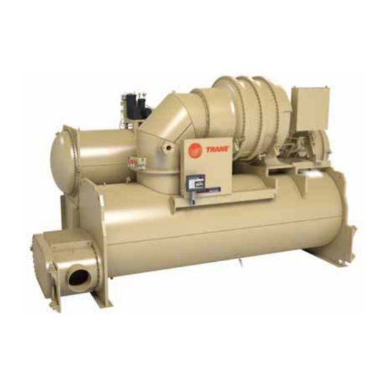
Pre-Installation Unit Components N ot e: The control panel side of the unit is always designated as the front side of the unit. Figure 3. Typical Simplex CVHH CenTraVac chiller Suction Elbow Econom izer Com pressor Oil Tank Assem bly... -
Page 15: Unit Clearances And Weights
Evaporat or dim ension t o left end for left hand t ube pull. Mot or Opt ional unit These dim ensions per m ount ed NEC Art icle 110 st art er 92 cm ( 3 ft ) CVHH-SVX001A-EN... -
Page 16: General Weights
Heaviest possible bundle and heaviest possible The unit weight information provided in Table 2 should be used for general information purposes only. Trane m otor com bination for the application fam ily does not recommend using this weight information for chiller. -
Page 17: Installation: M Echanical
18. A 63.5 m m (2.5 in.) diam eter lifting hole subm ittal package. is provided at each of these points. Im port ant : Trane w ill not assum e responsibility for 2. Attach the lifting chains or cables. equipm ent problem s resulting from an im properly designed or constructed 3. -
Page 18: Special Lift Requirements
Inform ation, ” p. N ot e: Disassem bly and reassem bly w ork includes dow el-pinning the com pressor and rem oving it from the unit. Contact Trane or an agent of Trane specifically authorized to perform start- ®... -
Page 19: Unit Isolation
Installation: M echanical location, contact Trane. For m ore inform ation, refer to Figure 7. Isolation spring placement by shell size, “ Factory Warranty Inform ation, ” p. evaporator and condenser length Unit Isolation I sola t or Con figu r a t ion 1... -
Page 20: Leveling The Unit
Leveling the Unit The chiller m ust be set level w ithin 1.6 m m (1/16 in.). 1. M easure and m ake a punch m ark an equal distance up from the bottom of each foot of the chiller. CVHH-SVX001A-EN... - Page 21 N ot e: Use of a laser level is an acceptable alternative m ethod to level the unit. Im port ant : Im m ediately report any unit dam age incurred during handling or installation at the job site to the Trane sales office. CVHH-SVX001A-EN...
-
Page 22: Installation: Water Piping
NOTICE: tim e. Expenses that result from a failure to follow this recom m endation w ill not be paid by Trane. Over-pressurization! Piping suggestions for each of the water circuits listed... -
Page 23: Cvhh-Svx001A-En
N ot e: In the case of a horizontal pipe, m ounting the sensor in the side of the pipe is preferred. In the case of a vertical pipe, m ounting the sensor in a place w here the water flow s upwards is preferred. CVHH-SVX001A-EN... -
Page 24: Cvhh-Svx001A-En
Do Not Apply Electrical Power to a Unit in N ot e: The “ Tem p” potentiom eter on the ifm efector control m odule has no effect in Trane a Vacuum! application. It is not necessary to m ake Failure to disconnect power to units w ith adjustm ents to the “... -
Page 25: Evaporator And Condenser Water Piping
Expenses that result from a failure to follow this recom m endation w ill not be paid by Trane. Figure 12. Typical evaporator water piping circuit Water piping connection sizes and com ponents are identified in Table 4, p. -
Page 26: Water Piping Connections
(i.e., drainage, etc.). N ot e: Plug-type sensor extension cables are available for purchase from Trane Parts Service if needed. These sensor extension cables m ay be necessary if the waterboxes are changed or if the tem perature sensors are m oved out into the unit piping for better m ixed tem perature readings. -
Page 27: Grooved Pipe Coupling
Cust om er attenuate vibration and prevent stress at the waterbox m arine only) provided connections. Flange adapters are not provided for CVHH Vict aulic coupling Trane provided units w ith 2068.4 kPa or 300 psig waterboxes that have CVHH... -
Page 28: Victaulic Gasket Installation
15.25 21.9 48.3 323.9 1- 1/ 8 x 5- 3/ 4 17.75 32.0 70.5 ( a) Bolt size for convent ional flange t o flange connect ion. Longer bolt s are required when flange washer m ust be used. CVHH-SVX001A-EN... -
Page 29: Bolt-Tightening Sequence For Water Piping Connections
Always perform as a hydro pressure test w ith water present in piping and waterboxes. Waterside design pressure is either 1034.2 or 2068.4 kPag (150 or 300 psig); refer to unit nam eplate or to subm ittal docum entation. CVHH-SVX001A-EN... -
Page 30: Vent Piping
R-1233 (E), but the glue that joins ® valves, rupture m em bers (as used on Trane the sections of plastic pipe m ay not be. When centrifugal chillers), fusible plugs, or pilot-operated considering a vent system constructed of plastic valves. -
Page 31: Vent Line Installation
Provide support as needed for the vent line. Do not use the rupture disk assem bly to support the vent line piping. • Use a flexible connection betw een the vent-line and the rupture disk assem bly to avoid placing stress on CVHH-SVX001A-EN... - Page 32 Proper Refrigerant Vent Line Termination! Equipment Damage! Failure to properly terminate a refrigerant vent line Trane assumes no responsibility for equipment damage could result in equipment damage. Improperly caused by insufficient drainage of the drip leg. All vent- terminating a refrigerant vent line could allow rain to lines must be equipped w ith a drip leg of sufficient enter the line.
- Page 33 Vent Piping Figure 19. Illustrates rupture disk location, cross section of rupture disk Gasket Out side pipe assem bly Suct ion connect ion Rupt ure disk Bolt Note: Pipe connect ion is 3 in. NPT. CVHH-SVX001A-EN...
-
Page 34: Trane Ruptureguard
(E). The RuptureGuard system Equipment Damage! consists of a solid-m etal, (non-fragm enting) reverse- Trane assumes no responsibility for equipment damage buckling rupture disk, and autom atically re-seating relief caused by insufficient drainage of drip leg. All vent lines valve. The relief valve and the rupture disk are rated at the must be equipped w ith a drip leg of sufficient volume chiller ’s m axim um w orking pressure level. - Page 35 “ C” values t oget her and apply t he result t o Figur e 23, p. 4 . The CVHH unit is a Sim plex chiller and has ( 1) refrigerant circuit and ( 1) r elief device.
- Page 36 = M oody friction factor in fully turbulent flow • d = inside diam eter of pipe or tube, m m • ln = natural logarithm • = absolute pressure at outlet of discharge piping, kPa (atm ospheric pressure) CVHH-SVX001A-EN...
- Page 37 “ C” values t oget her and apply t he result t o Figur e 24, p. 4 . The CVHH unit is a Sim plex chiller and has ( 1) refrigerant circuit and ( 1) r elief device.
- Page 38 = M oody friction factor in fully turbulent flow • d = inside diam eter of pipe or tube, in. • ln = natural logarithm • = absolute pressure at outlet of discharge piping, psi (atm ospheric pressure) CVHH-SVX001A-EN...
-
Page 39: Insulation
Do not allow the insulation to be exposed to Operation outside of norm al design conditions as defined excessive sunlight. Store indoors or cover w ith above m ay require additional insulation; contact Trane for canvas to prevent exposure. further review. - Page 40 Suct ion Suct ion Pipe ( free cover elbow cooling only) Suct ion Cont rol connect ion panel support Pipe Educt or line Econom izer Pipe See Not es See Not es See Not e Evaporat or & & CVHH-SVX001A-EN...
-
Page 41: Installation: Controls
Wiring and Port Descriptions Figure 26 illustrates the UC800 controller ports, LEDs, rotary sw itches, and w iring term inals. The num bered list follow ing Figure 26 corresponds to the num bered callouts in the illustration. Front View CVHH-SVX001A-EN... -
Page 42: Communication Interfaces
LED and Table 11, p. 42 voltage (<30V) and high voltage circuits. describes their behavior in specific instances. Failure to do so could result in electrical noise that could distort the signals carried by the low-voltage w iring, including IPC. CVHH-SVX001A-EN... - Page 43 Installation: Controls Figure 28. Control panel: Tracer AdaptiView main unit assembly (show ing low voltage and higher voltage areas for proper routing of field w iring) 30 Volt Maxim um 30–120 Volt Maxim um CVHH-SVX001A-EN...
-
Page 44: Installing The Tracer Adaptiview Display
(B). base plate. N ot e: Ensure the Trane logo is positioned so that it w ill be at the top w hen the Tracer AdaptiView display is attached to the display support arm . -
Page 45: Adjusting The Tracer Adaptiview Display Arm
AdaptiView display to the support arm base. Use a 14 m m w rench to adjust the tension. • To adjust the left/right sw ivel of the entire display arm , use a 13 m m w rench to adjust the bolt labeled 4 in Figure CVHH-SVX001A-EN... -
Page 46: Electrical Requirements
• pow er supply w iring to the starter, • other unit control options present, and • any field-supplied control devices. CVHH-SVX001A-EN... - Page 47 Follow proper lockout/ tagout procedures to ensure the power cannot be inadvertently energized. For variable frequency drives or other energy storing components provided by Trane or others, refer to the appropriate manufacturer’s literature for allowable waiting periods for discharge of capacitors.
-
Page 48: Trane-Supplied Remote Starter Wiring
Electrical Requirements Trane-Supplied Remote Starter Wiring Table 13. Standard field power w iring requirements Pow e r Supply W ir in g St a r t e r Pa n e l t o St a r t e r Pa n e l... -
Page 49: Customer-Supplied Remote Starter Wiring
( c) Solid St at e St art er Fault input is used wit h low- and m edium - volt age, cust om er- supplied solid st at e st art ers only. ( d) Must be separat ed from 120 Vac and higher w ir ing. CVHH-SVX001A-EN... -
Page 50: Current Transformer And Potential Transformer Wire Sizing
( a) For AWG/ MCM equivalent s in m m , refer t o Table 12, p. 47. Wires, lugs, and fuses/ br eaker s are sized based on Nat ional Elect r ic Code NEC [ NFPA 70] and UL 1995. CVHH-SVX001A-EN... -
Page 51: Pow Er Supply Wiring
• Verify that the starter nam eplate ratings are com patible w ith the pow er supply characteristics and w ith the electrical data on the unit nam eplate. CVHH-SVX001A-EN... -
Page 52: Circuit Breakers And Fused Disconnects
Any ethernet cables being used by custom er to interface w ith the Trane chiller m ust L2 L1 L2 L1 be shielded ethernet cabling. - Page 53 Any ethernet cables being used by custom er to interface w ith the Trane chiller m ust be shielded ethernet cabling. The custom er is required to provide an overcurrent...
-
Page 54: Control Power Transformer (Cptr) Option
The standard unit-m ounted CPTR option shall have an enclosure w ith a disconnect and w ill require custom er- supplied pow er. CVHH and CDHH chillers have a low-voltage CPTR option and a m edium -voltage CPTR option. The CPTR option involves a single phase 4kVA transform er(s) and the oil pum p m otor circuit to be located together in an enclosure that is unit-m ounted. - Page 55 N ot e: Graphic labels (show n above) are used for CE application only. Im port ant : • Before servicing, disconnect all pow er sources and allow at least 30 m inutes for capacitors to discharge. • All electrical enclosures—unit or rem ote—are IP2X. CVHH-SVX001A-EN...
-
Page 56: Interconnecting Wiring
For variable frequency drives or other energy storing components provided by Trane m otor. The sim plest way to ensure that the overloads or others, refer to the appropriate manufacturer’s... -
Page 57: Starter To M Otor Wiring (Remote-M Ounted Starters Only)
Unit control panel M ounted Starters Only) Figure 31. Typical equipment room layout for units w ith Ground Wire Terminal Lugs remote-mounted starters Ground w ire lugs are provided in the m otor term inal box and in the starter panel. CVHH-SVX001A-EN... -
Page 58: Terminal Clamps
Bus Bars Wire Terminal Lugs Bus bars and extra nuts are available as a Trane option. Wire term inal lugs m ust be field supplied. Install the bus bars betw een the m otor term inals w hen using a starter that is: •... -
Page 59: Starter To Control Panel Wiring
47.) The purpose of this interlock is to m aintain the oil pum p signal in the event that a starter failure, such as w elded contacts, keeps the chiller m otor running after the controller interrupts the run signal. CVHH-SVX001A-EN... -
Page 60: M Edium Voltage Installation
N ot e: Trane assum es no responsibility for the design, docum entation, construction, com patibility, installation, start-up, or long term support of starters provided by others. -
Page 61: M Otor Supply Wiring
To lim it the effects of corona or ionization w ith cables carrying m ore than 2000V, Trane requires that the pow er cable have a m etallic shield, unless the cable is specifically listed or... - Page 62 The cover m ust be re-installed onto the m otor term inal box and all bolts installed. Do not operate the CVHH-SVX001A-EN...
-
Page 63: System Control Circuit Wiring (Field Wiring)
( b) I f t he Condenser Wat er Flow Proving I nput is a fact ory- inst alled ifm efect or flow- sensing device, t he secondary ( opt ional) field device for proof of flow connect s from 1X1- 6 t o 1K27- 4 ( binary input ; norm ally open, closure wit h flow) . Rem ove fact ory j um per when used. CVHH-SVX001A-EN... -
Page 64: Water Pump Interlock Circuits And Flow Sw Itch Input
This is a dry binary input; norm ally- 14 AWG, 600 volt copper w ire. For AWG/M CM open, closure for flow. Apply no external pow er. equivalents in m m , refer to Table 12, p. CVHH-SVX001A-EN... -
Page 65: Temperature Sensor Circuits
Figure 33. CVHH sensor locations See Det ail A Det ail A... -
Page 66: Optional Control And Output Circuits
CWR—Outdoor Option The outdoor tem perature sensor is sim ilar to the unit- Im port ant : Start-up m ust be perform ed by Trane or an m ounted tem perature sensors in that it consists of the agent of Trane specifically authorized to sensor probe and the m odule. -
Page 67: Operating Principles
Operating Principles General Requirements Figure 34. Pressure enthalpy curve, 3-stage Operation and m aintenance inform ation for CVHH chillers are covered in this section. This includes both 50 and 60 Hz centrifugal chillers equipped w ith the Tracer AdaptiView UC800 control system . This inform ation pertains to all... -
Page 68: Oil And Refrigerant Pump
24 psid). It is then filtered and sent to the braze plate heat exchanger oil cooler located above the oil tank and on to the com pressor m otor bearings. From the bearings, the oil drains back to the oil tank. CVHH-SVX001A-EN... - Page 69 20. M otor coolant filter 6.35 m m (0.25 in.) OD 10. Liquid refrigerant to pum p, 41.275 m m (1.625 in.) OD 21. Oil tank junction box enclosure 11. Econom izer 22. Oil pum p m otor term inal box CVHH-SVX001A-EN...
-
Page 70: M Otor Cooling System
The evaporator eductor line has a shut-off on the CVHH and CDHH chiller can result in death or valve m ounted on the evaporator. Norm ally, the valve serious injury. -
Page 71: Ruptureguard
When the purge refrigeration system is running, refrigerant from the chiller condenser is attracted to the cold surface of the purge evaporator. When the gaseous refrigerant contacts the surface of the purge evaporator CVHH-SVX001A-EN... - Page 72 Operating Principles Figure 39. Components of a Trane EarthWise purge system (front view ) 1. Purge t ank 2. Condensing unit ( includes com pressor, condenser coil, and fan) 3. Pressure- relief device ( fusible plug) 4. Pum p- out solenoid valve 5.
- Page 73 Operating Principles Figure 40. Components of a Trane EarthWise purge system (back view ) 1. Regenerat ion solenoid valve 2. Pressure- relief valve 3. Exhaust solenoid valve 4. Pum p- out com pressor 5. Carbon t ank heat er 6. Aut om at ic expansion valve 7.
- Page 74 Purge Carbon Regen Tem perature Lim it Exceeded the pum p-out solenoid valve and the exhaust solenoid diagnostic is generated. valve. The purge system draw s its control pow er from the pow er supplies of the chiller control panel. CVHH-SVX001A-EN...
-
Page 75: Start-Up And Shut-Dow N
This diagram can be thought of as a state chart, w ith the Figure 41. Software operation overview Power Stopped Stopped Run Inhibit Starting Stopping Auto Fast Restart or Satisfied Setpoint Preparing to Shut Down Waiting to Start Shutting Down Starting Compressor Stop Command or Diagnostic Running Running Running - Limit CVHH-SVX001A-EN... -
Page 76: Start-Up Sequence Of Operation-Wye-Delta
Confirm 82.7 kPad (12 psid) Oil Pressure Within 3 min Enforce Stop to Start Timer Using Values From Check for High Vacuum Real Time Clock (5–200 sec, 30 is Default) Lockout Initialize Oil Vent Line Valve to Minimum Open Position CVHH-SVX001A-EN... - Page 77 Open Oil Vent Line Valve Compressor Confirm No Compressor Currents Within 0–30 sec Hold position of Oil Vent Line Valve De-Energize Condenser Water Pump Relay *Note: No oil pressure is less than 20.7 kPad (3 psid) Enforce All Running Mode Diagnostics CVHH-SVX001A-EN...
-
Page 78: Power Up Diagram
Ice building w ill be term inated either by opening the contact or based on entering evaporator fluid tem perature. The control panel w ill not perm it the Ice Building m ode to be CVHH-SVX001A-EN... - Page 79 Water Pump Relay Ignore Evap Pump Energize Head Relief Off Delay Time Request Relay Heat Relief Request Relay for Ice Building Delay (1–60 min) De-Energize Compressor Enforce All Limits and Running Mode Diagnostics Confirm No Compressor Currents Within 8 sec CVHH-SVX001A-EN...
-
Page 80: Free Cooling Cycle
Heating is the prim ary m ission and cooling is a waste product or is a secondary m ission. This type of operation requires an endless source CVHH-SVX001A-EN... -
Page 81: Control Panel Devices And Unit-M Ounted Devices
N ot e: Graphic labels (show n above) are used for CE application only. Im port ant : • Before servicing, disconnect all pow er sources and allow at least 30 m inutes for capacitors to discharge. • All electrical enclosures—unit or rem ote—are IP2X. CVHH-SVX001A-EN... -
Page 82: Daily Unit Start-Up
Table 20, p. 92 When the cooling requirem ent is satisfied, the control Table 21, p. 93 should be perform ed by qualified Trane panel originates a Shutting dow n signal. The inlet guide service technicians. vanes are driven closed for 50 seconds, the com pressor stops, and the unit enters a 3-m inute post-lube period. -
Page 83: Earthwise Purge Sequence Of Operations
Follow ing the initial data collection period, the adaptive m ode custom izes the purge refrigeration circuit operation during tw o distinct chiller operating conditions: • Chiller com pressor On • Chiller com pressor Off CVHH-SVX001A-EN... - Page 84 3 m inut es < Pum pout Tim e ≤ 5 m inut es 2 hours 5 m inut e < Pum pout Tim e ≤ 8 m inut es 1 hour Pum pout Tim e > 8 m inut es No Off cycle CVHH-SVX001A-EN...
- Page 85 On and pum p-out has been initiated by the purge unit controls. Exhaust Circuit Check. appears if a pum p-out has been initiated by an operator. Pumpout Inhibited. appears if the purge refrigeration circuit is On but pum p-out has been inhibited by a low condenser saturation tem perature. CVHH-SVX001A-EN...
- Page 86 As the non-condensables are rem oved from the purge tank, the condensing-unit com pressor suction tem perature increases. The purge CVHH-SVX001A-EN...
-
Page 87: Air Removal
The therm al siphon rate is reduced and, consequently, so The controller uses the non-condensable pum p-out is the am ount of heat transfer. A corresponding reduction algorithm to determ ine w hen to initiate, control, and CVHH-SVX001A-EN... -
Page 88: Carbon Tank And Regeneration Subsystem
100 - (pum p-out m inutes since last regen/pum p-out solenoid valve. m inutes at 100% capacity)* 100 N ot e: For purge system s equipped w ith standard pum p- out com pressors, operation at low chiller CVHH-SVX001A-EN... - Page 89 3. M onitor the carbon tem perature until it reaches the regeneration tem perature value of 115.6° C (240° F), and control w ithin a ±5.6° C (±10° F) dead band for 15 m inutes (this step should take approxim ately 3 hours). CVHH-SVX001A-EN...
- Page 90 Tracer AdaptiView display. The purge com ponent tem perature and is useful for m onitoring regeneration and screen is accessible from the purge touch target on the for diagnosing regeneration system problem s. hom e screen of the display. CVHH-SVX001A-EN...
-
Page 91: Recommended M Aintenance
Only genuine Trane replacement components w ith identical Trane part numbers should be used in Trane CenTraVac chillers. Trane assumes no responsibility for damages resulting from the use of non-compatible parts or materials. This section describes the basic chiller preventive m aintenance procedures, and recom m ends the intervals at w hich these procedures should be perform ed. -
Page 92: Normal Operation
® I nspect and clean t he ifm efect or flow det ect ion sensors. Subm it a sam ple of t he com pr essor oil t o a Trane- qualified laborat ory for com prehensive analysis. CVHH-SVX001A-EN... -
Page 93: Compressor Oil Change
An access valve is installed in the oil supply line, before the oil filter, for obtaining oil sam ples. N ot es: • Use only Trane OIL00022. A full oil change is 79.5 L (21 gallons). CVHH-SVX001A-EN... -
Page 94: Ruptureguard M Aintenance
Do not use non- vicinity. approved refrigerants, refrigerant substitutes, or refrigerant additives. Weekly M aintenance Perform the follow ing m aintenance procedure on a w eekly basis: CVHH-SVX001A-EN... -
Page 95: Semi-Annual M Aintenance
Purge Daily Pum pout Exceeded diagnostic, been serviced, several filter-drier assem bly changes m ay w hich w ill shut off the purge system . You can disable the be required before a satisfactory m oisture level is CVHH-SVX001A-EN... -
Page 96: Recommended System M Aintenance
Leak Testing Im port ant : If leak testing is required, contact a Trane service agency. WARNING Recommended System M aintenance... - Page 97 Be sure to consult any qualified chem ical house in the every tw o to three years. Trane recom m ends that anode area (one fam iliar w ith the local water supply’s...
-
Page 98: Waterbox Removal And Installation
WARNING 1. Determ ine the type and size of chiller being serviced. Overhead Hazard! Refer to Trane nam eplate located on chiller control panel. Failure to follow instructions could result in death or serious injuries. Never stand below or in close... -
Page 99: Reassembly
94.9–122.0 ( 70–90) 3/ 4 339.0 ( 250) 142.4–210.2 ( 105–155) Table 24. CVHH waterbox weights N on - M a r in e N on - M a r in e M a r in e Pla t e... - Page 100 Waterbox Removal and Installation Table 24. CVHH waterbox weights (continued) N on - M a r in e N on - M a r in e M a r in e Pla t e M a r in e D om e...
-
Page 101: Bolt-Tightening Sequence For Waterboxes
For heat recovery condenser waterbox covers, torque the bolts along the center divider of the waterbox first (1A, 2A, 3A, etc), and then torque the bolts around the outside of the waterbox (1B, 2B, 3B, etc). 7B 11B 15B CVHH-SVX001A-EN... -
Page 102: Forms And Check Sheets
Forms and Check Sheets The follow ing form s and check sheets are included for use w ith Trane start-up of CVHH CenTraVac chillers. Form s and check sheets are used, as appropriate, for installation com pletion verification before Trane start-up is scheduled, and for reference during the Trane start-up. - Page 103 Request for Trane Service Im port ant : A copy of this com pleted form m ust be subm itted to the Trane service office that w ill be responsible for the start-up of the chiller. Start-up w ill NOT proceed unless applicable item s listed in this form have been satisfactorily com pleted.
- Page 104 _______________________________________________________________________________________________________________ This docum ent and the inform ation in it are the property of Trane, and m ay not be used or reproduced in w hole or in part w ithout w ritten perm ission. Trane reserves the right to revise this publication at any tim e, and to m ake changes to its content w ithout obligation to notify any person of such revision or change.
- Page 105 CVHH Start-up Task List Start-up Tasks to be Performed By Trane WARNING Safety Alert! In addition to the follow ing tasks, you M UST: • Follow all instructions in the chiller’s Installation, Operation, and M aintenance manual, including w arnings, cautions, and notices.
- Page 106 Review “AdaptiView Display Custom er Training Checklist. ” – Equipm ent Description – Stopping/Starting Chiller Operation – Alarm s – Reports – Data Graphs – Equipm ent Settings – Display Settings – Security Settings – Basic Troubleshooting Revised: 10 Oct 2014 CVHH Start-up Task List...
- Page 107 CVHH Annual Inspection List Follow the annual maintenance instructions provided in the text of this manual, including but not limited to: Compressor M otor • M otor continuity. • M otor m eg test. • Check m otor term inals.
- Page 108 • Inspect anodes. • Inspect and lubricate hinged waterboxes. • With water flow sensing option, bleed tubing from waterboxes to transform ers. Revised: 10 Oct 2014 CVHH Annual Inspection List...
- Page 109 Operator Log Water-Cooled CVHH CenTraVac Chiller w ith UC800 Controller Tracer AdaptiView Reports—Log Sheet Log 1 Log 2 Log 3 Eva por a t or Ent ering Leaving Sat urat ed Refrig. Press Approach Flow Sw St at us Con de n se r...
- Page 111 HVAC system s, com prehensive building services, and parts. For m ore inform ation, visit w w w.Trane.com . Trane has a policy of continuous product and product data im provem ent and reserves the right to change design and specifications w ithout notice.
Need help?
Do you have a question about the CVHH and is the answer not in the manual?
Questions and answers