Advertisement
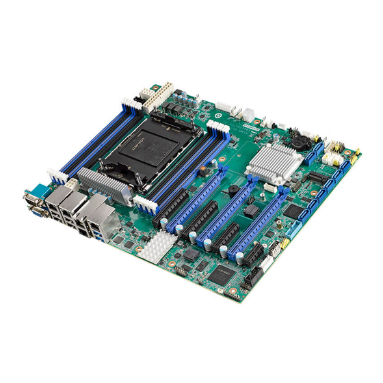
ASMB-817 Series LGA 4677 Intel 4th Generation Xeon
Scalable ATX Server Board with 8 DDR5, 3 PCIe x16,
8 SATA3, 4 USB3.2 (Gen1), Dual 10GbE, IPMI
Startup Manual
Packing List
Before you begin installing your card, please make sure that
the following items have been shipped:
• 1 x ASMB-817 Startup Manual
• 2 x SATA data cables
• 2 x SATA power cables
• 2 x CPU power cables (8P)
• 1 x CPU carrier
• 1 x I/O port bracket
• 1 x M.2 screw
If any of these items are missing or damaged, please con-
tact your distributor or sales representative immediately.
Specifications
Standard M/B Functions
• CPU: LGA4677 Intel 4th Generation Xeon
processors
• BIOS: AMI 512 Mbit SPI BIOS
• Chipset: Intel
C741 PCH
®
• System Memory: 8* DDR5 4400/4800
Registered ECC DIMM, Max. Capacity 512 GB
Note:
Due to the inherent limitations of older PC archi-
tectures, the system may not fully detect 512 GB
RAM when 512 GB RAM is installed.
For more information on this and other Advantech
products, please visit our website at:
http://www.advantech.com
For technical support and service, please visit our
support website at:
http://support.advantech.com
Register your products on our website and get 2
months extra warranty for Free at:
http://www.register.advantech.com
This manual is for the ASMB-817 series Rev. A1.
Part No. 2042081700
Printed in China
Specifications (Cont.)
• SATA Interface: 8 x SATA3 6Gb/s ports Intel Rapid
• Serial Ports: One onboard header, only supports RS-232
• Keyboard/Mouse Header (KBMS1): Supports the stan-
• Watchdog Timer: 255 level timer intervals
• USB Port: Supports up to 4 x USB 3.2(Gen1) ports (2
VGA Interface
• Chipset: ASPEED AST2600
• Display Memory: 64 MB
• Resolution: Supports VGA up to resolution 1920 x 1200
Ethernet Interface
• Interface: 10/100/1000 Mbps & 10 GbE Base-T
Scalable
®
• Controller: LAN1/2: Intel I210; LAN3/4: Intel X710
Mechanical and Environment
• Dimensions (L x W): 244 x 304 mm (9.6" x 12")
• Power Supply Voltage: +3.3 V, +5 V, +12 V, +5 Vsb
• Power Consumption (mainboard only, excluding IO
• Operating Temperature: 0 ~ 60° C (depending on CPU)
• Net Weight: 0.97 kg
The board has a number of jumpers that allow you to con-
figure your system to suit your application. The table below
lists the function of each of the jumpers and connectors.
Connectors
Label
ATXPWR1
ATX12V1, ATX12V2
BH2
BIOS_SKT1
COM2
1st Edition
CPUFAN0
January 2023
Storage (for Windows only) (SATA0-SATA7 supports
software RAID* 0, 1, 10 & 5) * Limited support
dard PS/2 keyboard and mouse via PS/2 cable.
ports from onboard 20-pin header) and 9 x USB 2.0 ports
(1*Type-A, 4 ports from onboard 10-pin header)
@ 60 Hz refresh rate
device): Max. load: +3.3 V @ 1.239 A, +5 V@ 1.314 A,
+12 V @ 0.052 A,+5 Vsb @ 0.7 A, 12 V_8P @ 20.833 A
Function
ATX 24-pin main power connector
Processor power connector (for CPU0)
For optional battery kit
BIOS SPI ROM
Serial port: RS-232
CPU FAN connector
ASMB-817 Startup Manual 1
®
Advertisement
Table of Contents

Related Manuals for Advantech ASMB-817 Series


Summary of Contents for Advantech ASMB-817 Series
- Page 1 Free at: ATX12V1, ATX12V2 Processor power connector (for CPU0) http://www.register.advantech.com For optional battery kit BIOS_SKT1 BIOS SPI ROM This manual is for the ASMB-817 series Rev. A1. COM2 Serial port: RS-232 Part No. 2042081700 1st Edition CPUFAN0 CPU FAN connector...
- Page 2 Jumpers and Connectors Jumpers and Connectors (Cont.) Jumper list DIMMA1, DIMMB1, DIMMC1, DIMMD1, DDR5 slot Label Function DIMME1, DIMMF1, DIMMG1, DIMMH1 JCASE1 Chassis case open alarm EXT_THR1 Connector for external thermistor JCMOS1 CMOS clear GPIO1 GPIO connector JFP1, JFP1+JFP12 Front panel header HDAUD1 Audio header JME1...
- Page 3 Installation Note (Cont.) Installation Note (Cont.) 2.0 mm JFP1 connector on board 2.0 mm JFP1 connector to 2.54 mm pitch header Description Pin Number Description Description Pin Number Description RST BTN ▼1 PWD BTN (Red) PWD BTN ▼1 RST BTN (White) PWD GND PWD GND (Black) PWD GND...
Need help?
Do you have a question about the ASMB-817 Series and is the answer not in the manual?
Questions and answers