Table of Contents
Advertisement
Quick Links
Advertisement
Table of Contents

Related Manuals for Kimo DBM610


Summary of Contents for Kimo DBM610
- Page 1 DBM610 AIRFLOW METER...
-
Page 3: Table Of Contents
3.1. Mounting of frame..............................9 3.2. Setting of the cloth..............................10 3.3. Setting of rods................................. 11 4. Using DBM610 in airflow meter mode..........................12 4.1. Starting up................................12 4.2. Configure the airflow meter............................. 12 4.2.1. Set the correction coefficient........................... 12 4.2.2. -
Page 4: Introduction
DBM610 airflow meter allows control and balancing of airflow in air conditioning system. Thanks to the interchangeable hoods, the airflow can be used on any type of grids or diffusers in air supply or exhaust. Easy to handle, lightweight, it allows accurate, sturdy and fast measurements. -
Page 5: General Technical Features
Accuracy: K, J, T: from -200 to 0 °C: ±0.4°C ±0.3% of reading from 0 to 1300 °C: ±0.4°C S: ±0.6°C Resolution: 0.1°C Pressure: • Measuring range: from -2500 to +2500 Pa Accuracy: ±0.2% of measuring ±2 Pa Resolution: from 0.001 to 0.1 Pa Tolerated overpressure: 34473 Pa 1.3. -
Page 6: Presentation Of Airflow Meter
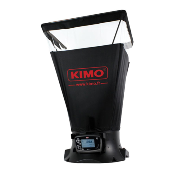
2.1. Base Outside of the base: • Carrying handle Protective cover Location for the electronic housing Button of point/point measurement start Electronic card Integrated ergonomic handle Inside the base: • Silicone tube for pressure routing Two pressure connectors Receipt cup hood rods Measurement grid Temperature probe Presentation of airflow meter... -
Page 7: Grid
2.2. Grid The measurement grid is fixed to the base in 6 points and is made up of the following elements: two chambers (for total pressure and for static pressure) • 2 pressure connectors • 2 pressure connectors The measurement grid allows to measure differential pressure. It takes into account atmospheric pressure and temperature compensation and works automatically in supply or exhaust. -
Page 8: Airflow Meter Mode
2.3.1. Airflow meter mode In airflow meter mode, the device has following functions: Simultaneous display of airflow, pressure and temperature • Automatic airflow direction (supply or exhaust) • Automatic average and point by point average • HOLD function (measurement is fixed) •... -
Page 9: Hoods
2.4. Hoods Frame with a foam to ensure a good airtight with ceiling Transparent mica allowing a good visibility and making easy the position Frame rods of the hood Cloth of the hood Elastic to hold the hood on the base 3.1. -
Page 10: Setting Of The Cloth
3.2. Setting of the cloth Before set the cloth on the frame, frame must be mounted. ➢ First, insert a corner of the frame inside a corner of the cloth. ➢ Insert the opposite corner of the frame in the corresponding corner of the cloth. The colour mark must be in the middle of the frame side. -
Page 11: Setting Of Rods
➢ Slightly bend the rod and insert the flat end of the rod on the opposite corner of the holding cup. The crossing rods must be on the same plan as the KIMO logo. ➢ Proceed the same way for the three other rods. -
Page 12: Using Dbm610 In Airflow Meter Mode
➢ Go to "Standard airflow" then press OK. ➢ Select ON or OFF with up and down arrows then press OK. When standardized airflow is activated, "NORMO" indication is shown on screen on the left of time. Using DBM610 in airflow meter mode... -
Page 13: Perform Averages
➢ Press "Esc" to cancel and not include these results. It will be possible to launch a new measurement. ➢ Press "Save" to save results. Screen displays the following results in the left column: Left column: measurement results • Right column (Σ): aggregate of averages on several datasets of automatic averages • Using DBM610 in airflow meter mode... -
Page 14: Using Dbm610 In Micromanometer Mode
➢ Select the required dimensions with up and down arrows then press OK. ➢ If necessary, modify the length then the width with arrows then press OK (if no modification, just press OK). Set diameter of the surface: ➢ Go to "Surface" then press OK. Using DBM610 in micromanometer mode... -
Page 15: Set Measurement Units
➢ Select ON or OFF with up and down arrows then press OK. 5.2.6. Set the thermocouple type ➢ Go to "Thermocouple" line then press OK. ➢ Select thermocouple type: K, J, T or S with up and down arrows then press OK. Using DBM610 in micromanometer mode... -
Page 16: Set The Compensation Temperature
The Matrix grid is designed for the air velocity measurement on any types of celling vents or diffusers with a large useful area. To use the DBM610 in Matrix grid mode, place the grid on the telescopic pole and add the positioning struts that will be against the celling. Struts are available in 3 different lengths: 3 x 5 cm •... -
Page 17: Point/Point Automatic Average
The device displays both of the fixed values: on the right the first value and on the left the second value. ➢ Press “Hold” to restore the display of the first value only. ➢ Press “Esc” to quit the “Hold” mode. The device displays the current measured values. Using DBM610 in micromanometer mode... -
Page 18: Manage Dataset Recordings
This part allows to display or delete recorded dataset in the device. To get to dataset from "Measurement "screen: ➢ Press "Menu" or "Save" button. ➢ Go to "Savings" with left and right arrows. ➢ Press OK. 6.1. Get to recorded datasets ➢... -
Page 19: Set The Device
This part allows to set the different general parameters of the device. ➢ Go to "Menu". ➢ Go to "Settings" with left and right arrows. ➢ Press OK. 7.1. Set date and time ➢ Go to "Date/Time" line then press OK. ➢... -
Page 20: Information About The Device
➢ Press Esc to back to "Informations" menu. 8.3. After sales service ➢ Go to "After sales service" then press OK. Screen displays Kimo after sales services phone number and email. ➢ Press Esc to back to "Informations" menu. Information about the device... - Page 24 Once returned to KIMO, required waste collection will be assured in the respect of the environment in accordance to 2002/96/CE guidelines relating to WEEE.
Need help?
Do you have a question about the DBM610 and is the answer not in the manual?
Questions and answers