Table of Contents
Advertisement
Advertisement
Table of Contents

Related Manuals for Kimo VT 200


Summary of Contents for Kimo VT 200
- Page 1 Anemometer Supplied Calibration with VT 200 certificate...
-
Page 3: Table Of Contents
Table of contents I – Technical specifications.....................4 Technical features..........................4 Specifications............................4 II – Introduction........................5 Description..............................5 Connections..............................6 III – Browsing........................7 IV – Menus..........................8 Probe menu...............................8 Using wire probes and modules......................8 Using wireless probes..........................8 Airflow menu............................8 Area..................................8 Duct type................................8 Sizes..................................8 K2 factor................................8 Units..................................9 Using Hotwire............................9 Air velocity menu.............................9 Hold - Min/Max............................9... -
Page 4: I - Technical Specifications
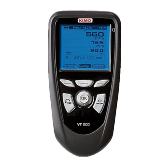
I – Technical specifications Technical features Sensing elements Display.......Graphic display 128x128 pixels Dim. 50 x 54 mm, blue blacklit, Display of 6 measurements (including 4 simultaneously) Hot wire : Air velocity : thermistance with a negative temperature coefficient. Housing......IP54, ABS shock-proof Ambient temperature : Pt100 1/3 Din. -
Page 5: Introduction
C2 mini-Din C1 Hour connector connector Value Side view Power suply Unit connection Circular USB port for menu KIMO Cable Elastomer protection Keypad Access keys for circular meny Browsing joystick : 4 directions ● Validation ● On/Off key Escape key... -
Page 6: Connections
II – Introduction Connections Interchangeable measurement modules Interchangeable modules with Smart-plus system are automatically recognized when connected to the instrument. 1. Current / voltage module 2. Thermocouple module It allows current or voltage measurements on V/A1 or VA/2 It allows thermocouple temperature measurement on Tc1, channels with current/voltage input cables or ammeter Tc2, Tc3 and Tc4 channels with type K, J or T with wire... -
Page 7: Browsing
III – Browsing Power-up Enter key code with directional pad. (if the locking is activated) e Homepage display Select a sub menu with access keys or with arrow keys Infos Probes Params Probe connection Probe display ... -
Page 8: Menus
IV – Menus Probe menu 1. Using wire probes and modules Probes display Wire probes and modules with Smart-plus system are automatically recognized from first connection. The ''Probe'' menu only appears when probes or module are connected. This menu allows to view probe information plugged to C2, Module, C1 or wireless connections. -
Page 9: Units
Sensing element (air velocity) Sensing element (temperature) 1. Connect the hotwire probe to VT 200. Probe menu appears. 2. Slide down protection tube (1). Air flow direction 3.The probe must be perpendicular to airflow : the red point at the bottom of the probe must Protection tube (1) face airflow. -
Page 10: Configuration
IV – Menus Configuration If you use thermocouple probes, you must enter type Configuration sub-function allows to: : into the Configuration sub-function. • Select thermocouple Click on OK or to enter into sub function : a list of thermocouple available ( K, J or T type) appears . Select type with ... - Page 11 IV – Menus 2. Launch a planned dataset A planned dataset is composed of several locations. For each location, the operator can enter a theorical value and a tolerance for the parameter to be controlled. Planification must be made via the software. a.
-
Page 12: Parameters
IV – Menus Parameters • Language Click on OK or to enter and a list of languages available appears. Select language with arrow keys and and Confirm wih OK. • Date / Time Click on OK or to enter into sub function. Enter the day with and then move to the next digit with . Repeat this operation for the month, year, hour and minute. -
Page 13: General Information
4. Replace the front. Maintenance KIMO performs calibration, adjustment and maintenance of all your instruments to guarantee a constant level of quality of your measurements. In regards of Quality insurance norms, we recommend that the instruments are checked once a year. - Page 16 Once returned to KIMO, required waste collection will be assured in the respect of the environment in accordance to 2002/96/CE guidelines relating to WEEE.
Need help?
Do you have a question about the VT 200 and is the answer not in the manual?
Questions and answers