Table of Contents
Advertisement
Advertisement
Table of Contents

Related Manuals for Kimo mp210


Summary of Contents for Kimo mp210
- Page 1 MP 210 Thermo-Anemo-Manometer...
-
Page 3: Table Of Contents
Table of contents 1.Presentation............................6 1.1. Instrument description........................6 1.2. Keys description...........................6 1.3. Remove battery..........................7 2.Connections of the MP210........................8 2.1. Main features..........................8 2.2. Connections..........................8 3.Information............................10 4.Set the instrument..........................11 4.1. Set language..........................11 4.2. Modify date and time........................11 4.3. Activate or deactivate the beep key...................11 4.4. - Page 4 8.4. Gas leak.............................25 8.4.1 Unit............................25 8.5. CO/temperature probe.......................25 8.5.1 Unit............................25 8.5.2 Alarm............................25 8.6. Tachometry..........................25 8.6.1 Unit............................25 8.6.2 Type.............................25...
-
Page 6: Presentation
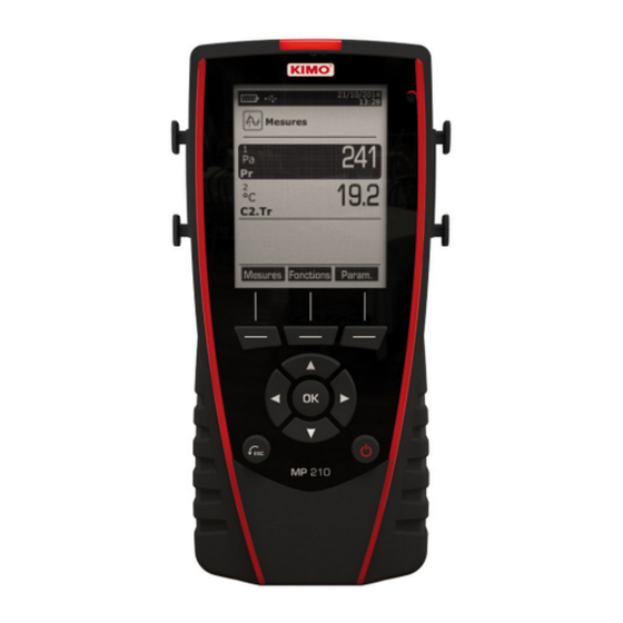
1.1 Instrument description Battery Date and time level Dataset menu Measurement menu Information menu Configuration menu Home screen Function keys OK button Navigation arrows ESC button On/Off button 1.2 Keys description ➢ Left key: allows to navigate from left to right ➢... -
Page 7: Remove Battery
1.3 Remove battery ➢ Turn off the instrument. ➢ Turn it over. ➢ Press the red button while sliding down the battery. Presentation... -
Page 8: Connections Of The Mp210
The interchangeable modules have the SMART-2014 system and are automatically recognized once the connection is made on the instrument. Thermocouple module: • Allows to measure temperature on Tc1, Tc2, Tc3 and Tc4 channels with wired thermocouples K, J, T or S probes ended with a male miniature connector Connections of the MP210... - Page 9 Wireless probe / instrument communication • Wireless communication between probe and instrument with automatic recognition after power-up. Wireless probes shall be located near the instrument for initial recognition. Connection between HQ210 and wireless probes must be established. Connections of the MP210...
-
Page 10: Information
“Information” menu allows to view information about the instrument, probes and module connected to the “Wireless probe”, “Mini-DIN 1”, “Mini-DIN 2” or “Module” connections. To enter in this menu from home screen, select the “Information” menu with the arrow keys then press OK. Available information for probes and module is : Type of probes and module •... -
Page 11: Set The Instrument
The instrument is on. ➢ With the arrow keys, go to “Configuration” menu. ➢ Press OK.. 4.1 Set language “Configuration” screen is displayed. ➢ Select “Language” with the arrow keys then press OK. Available languages are displayed. ➢ Press Up and Down arrows to select the required language : FRA, ENG... ➢... -
Page 12: Set Backlight
4.5 Set backlight “Configuration” screen is displayed. ➢ Select “Backlight” with arrow keys then press OK. ➢ Select the backlight level between 1 and 9 or “Auto” with Up and Down keys. ➢ Press OK to validate. 4.6 Set security This part allows to activate or deactivate a security code. -
Page 13: Set The Probes
5.1 Use of the wire probes and modules Connect a probe • ➢ Connect the mini-DIN cable on the mini-DIN connection of the probe. ➢ Connect the mini-DIN cable with the probe on the instrument. A beep indicates that the operation has been correctly performed. Arrow in front of the user Arrow in front... -
Page 14: Use Of Wireless Probes
Use of wireless probes Add a wireless probe • With arrow keys, go to On the bottom of the Turn on the wireless In “Information” menu go to “Information” menu screen press the probe and keep it press “Wireless probe” then press then press OK. -
Page 15: Channel Configuration
The channel configuration allows to modify the displaying of the measured parameters. The instrument is on. ➢ With the arrow keys, go to “Measurement”. Press OK. ➢ Press the function key “Channels”. ➢ The different functions of the probe are displayed. IIt is possible from the “Channels”... -
Page 16: Vanes And Hot Wire
*For a Ø100 mm vane probe, K factor is not available . It is possible to select “Cone” in addition to “Rect” and “Circ” : ➢ To select “Cone”, go to the line “Cone” then press OK. Select the type of cone : K25 or K85 and press OK. •... -
Page 17: Delta T
6.3 Delta T Connect the thermocouple module then the probes. ➢ In the “Channels” menu : ➢ Select with arrow keys the sub-menu “Delta T” then press OK. ➢ Select “Channel number” and press OK. Select a channel number and press OK. ➢... -
Page 18: Start And Record Datasets
The instrument in on. ➢ Select with arrows keys “Measurement” menu. Press OK. ➢ ➢ Select with arrows keys the measurement in which the dataset will be performed. Press “Functions” key then select “Dataset” with arrow keys and press OK. ➢... -
Page 19: View The Recorded Datasets
Press the function key “Validate” when the duration is set. ➢ Press OK on the line “Interval”. ➢ Go to “min” with the arrow keys then press OK, set the duration with arrow keys then press OK. ➢ ➢ Perform the same procedure for the seconds. Press the function key “Validate”... -
Page 20: Automatic Average
➢ Select the letters with arrow keys then press OK. To go from the lower case keypad to the upper case keypad then to the numeric keypad : press the function key : To delete a letter press the function key “Delete”. ➢... -
Page 21: Comax
➢ Press the function key “Validate” when the interval is set. Press OK to start the measurement. ➢ A the end of the measuring dataset, measurements, average, minimum and maximum values, standard deviation and duration are displayed. ➢ Press OK to add a new measuring point to the calculation. The countdown starts. -
Page 22: Setting Of Measurement Parameters
The instrument is on. ➢ Go to “Measurement” menu with the arrow keys and press OK. ➢ Select the measurement to set with the arrow keys. Press the function key “Params”. ➢ The different parameters are displayed. ➢ For all probes and modules, it is possible to modify the channel number. Select “Channels”... -
Page 23: Alarm
8.1.4 Alarm Température : Go to the line “Temp.alarm” and press OK. ➢ Select “High alarm” and/or “Low alarm” by pressing OK. ➢ It is possible to set the high and low thresholds. Go to the line “High threshold” and press OK. ➢... -
Page 24: Vane Probe And Hotwire Probe
8.3 Vane probe and hotwire probe 8.3.1 Unit Air velocity : ➢ Go to the line “Air velocity” and press OK. ➢ Select with the arrow keys the required unit : m/s, fpm, km/h or mph. ➢ Press OK to validate the unit selection. Temperature : Go to the line “Temperature”... -
Page 25: Gas Leak
8.4 Gas leak 8.4.1 Unit Go to the line “CH4” and press OK. ➢ Select the required unit : ppm, %vol, %LEL ➢ ➢ Press OK to validate the unit selection. 8.5 CO/temperature probe 8.5.1 Unit Temperature : Go to the line “Temperature” and press OK. ➢... - Page 28 Once returned to KIMO, required waste collection will be assured in the respect of the environment in accordance to 2002/96/CE guidelines relating to WEEE.
Need help?
Do you have a question about the mp210 and is the answer not in the manual?
Questions and answers