Table of Contents
Advertisement
Quick Links
Advertisement
Table of Contents

Related Manuals for Kärcher AP 100 M


Summary of Contents for Kärcher AP 100 M
- Page 1 AP 100/50 M Service Manual English 5.906-508.0 Rev. 00 (11/10)
-
Page 2: Table Of Contents
Preface ............4 Safety instructions . - Page 3 5.5.3 Replacing the abrasive coals of the suction turbine ....30 5.5.4 Replacing the suction turbine ....... . .
-
Page 4: Preface
Preface 2.2 Symbols on the machine High-pressure jets can be dangerous if im- Good service work requires extensive and practice- properly used. The jet may not be directed oriented training as well as well-structured training at persons, animals, live electrical equip- materials. -
Page 5: Setup And Function
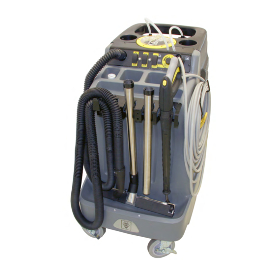
Setup and function 4.1 Front view 1 Suction hose connection 9 High pressure hose 2 Operator console 10 Spray lance 3 Cover dirt water reservoir 11 Guiding rolls with fixed position brake 4 Suction hose for detergent 12 Suction pipe 5 Dirt water reservoir 13 Floor nozzle 6 Connection of high pressure hose... -
Page 6: Rear View
4.2 Rear view 1 Sliding handle 7 Dirt water reservoir 2 Suction hose - detergent 8 Drainage hose for fresh water 3 Cover dirt water reservoir 9 Power cord 4 Suction hose 10 Dirt water discharge hose 5 Fresh water tank cover 11 Cleaning agent container 6 Fresh water tank English 5.906-508.0 Rev. -
Page 7: Right View
4.3 Right view 1 Cover dirt water reservoir 4 Fresh water tank 2 Fresh water tank cover 5 Drainage hose for fresh water 3 Suction hose 6 Dirt water reservoir English 5.906-508.0 Rev. 00 (11/10) -
Page 8: Left View
4.4 Left view 1 Suction hose connection 5 Dirt water discharge hose 2 Connection of high pressure hose 6 Cable hook, rotating 3 Sliding handle 7 high pressure hose 4 Dirt water reservoir 8 Hand blowing gun English 5.906-508.0 Rev. 00 (11/10) -
Page 9: View From Below
4.5 View from below 1 Water filter 4 Adjustment wheel for pressure control valve 2 Wheel support 5 Air outlet, suction turbine 3 Supply hose for fresh water English 5.906-508.0 Rev. 00 (11/10) -
Page 10: Control Terminal
4.6 Control terminal 4.6.1 Control elements 1 Fill hose, fresh water 6 Pump fuse 2 Suction hose connection 7 Pump switch 3 Switch for vacuuming 8 Dosage valve for detergent 4 Fuse for suction turbine 9 Connection of high pressure hose 5 Appliance switch ON/OFF Note 4.6.2 Dosage valve for detergent... -
Page 11: Operating Panel From Below
4.6.3 Operating panel from below 1 Switch of suction turbine 2 Fuse for suction turbine 3 Appliance switch ON/OFF 4 Pump fuse 5 Pump switch 6 Dosage valve for detergent English 5.906-508.0 Rev. 00 (11/10) -
Page 12: Suction Turbine
4.7 Suction turbine Note The suction turbine sits underneath the wastewater reservoir. 1 Connecting block 2 High pressure/low pressure solenoid valve 3 Detergent injector 4 Suction turbine English 5.906-508.0 Rev. 00 (11/10) -
Page 13: High-Pressure Pump
4.8 High-pressure pump 1 Pump motor 2 High-pressure pump 3 High pressure hose 4 Supply hose for fresh water English 5.906-508.0 Rev. 00 (11/10) -
Page 14: Hand Spraygun
4.9 Hand spraygun 1 Nozzle screws 3 Hand blowing gun 2 Spray lance 4 Lever for hand spray gun 1 Hand spray gun casing 2 Safety lever 3 Lever for hand spray gun 4 Corner valve English 5.906-508.0 Rev. 00 (11/10) -
Page 15: Floor Nozzle
4.10 Floor nozzle 1 Front vacuum lip 2 Rear vacuum lip 3 Floor nozzle 4 Adjustment wheel, height adjustment, impeller 5 Impeller English 5.906-508.0 Rev. 00 (11/10) -
Page 16: Scrubbing Brush
4.11 Scrubbing brush 1 Front vacuum lip 2 Rear vacuum lip 3 Scrubbing brushes 4 Water nozzles Note A scrubbing brush can be attached as an accessory to clean severely contaminated surfaces. English 5.906-508.0 Rev. 00 (11/10) -
Page 17: Wastewater Reservoir
4.12 Wastewater reservoir 1 Dirt water discharge hose 1 Rough dirt filter 2 Cover dirt water reservoir 2 Swimmer ball 3 Dirt water reservoir 1 Rough dirt filter with swimmer ball 2 Cleaning opening of the dirt water reservoir English 5.906-508.0 Rev. 00 (11/10) -
Page 18: Discharge Hoses
4.13 Discharge hoses 1 Dirt water discharge hose 2 Drainage hose for fresh water Note The fresh water drain hose is also used as a fill level display. For environmental protection reasons, the wastewa- ter must be disposed of according to its type of con- tamination. -
Page 19: Water Function Diagram
4.14 Water function diagram 20 19 18 1 high pressure hose 13 Dirt water reservoir 2 Suction hose 14 Suction turbine 3 Fill hose, fresh water 15 Detergent injector 4 Connection of high pressure hose 16 High pressure/low pressure solenoid valve 5 Dosage valve for detergent 17 Pressure relief valve 6 Suction hose connection... -
Page 20: Service Tasks
Service tasks 5.1 Control terminal 5.1.1 Remove operating panel 5.1.2 Removing the switch Preliminary tasks: Remove operating panel. 1 Fastening screw 2 Operator console 1 Fastening nut Unscrew the suction hoses for the detergent from 2 Cable connector the detergent containers. 3 Cover Unscrew locking screws. -
Page 21: Remove The Detergent Dosing Valve
5.1.3 Remove the detergent dosing valve Preliminary tasks: Remove operating panel. 1 Fastening nut 1 Turning handle Loosen the mounting nuts 2 Operator console Remove the dosing valve toward the rear. Pull off the rotary handle. Installation in reverse order Note Do not transpose the hoses during installation. -
Page 22: Remove The Connection Of The High Pressure Hose
5.1.4 Remove the connection of the high pressure hose Preliminary tasks: Remove operating panel. 1 High pressure hose connection nut 2 Connection of high pressure hose 1 Connection of high pressure hose 3 Spacer discs 2 High pressure hose Observe the number of spacers during installation. Separate the high pressure hose from the high pressure connection point of the appliance. -
Page 23: Remove The Fuses
5.1.5 Remove the fuses Preliminary tasks: Remove operating panel. 1 Fastening nut 2 Cable connector 3 Cover Remove the cable ties. Loosen the mounting nuts. Remove cover. 1 Operator console 2 Cover flap Pull out the connecting plug. Unscrew the fastening nut with the cover flap. Remove the fuse toward the rear. -
Page 24: Wastewater Reservoir
5.2 Wastewater reservoir 5.2.1 Removing the wastewater reservoir 5.2.2 Remove the drain hose for wastewater Preliminary tasks: Preliminary tasks: Empty the dirt water reservoir. Remove the wastewater reservoir. Remove operating panel. 1 Hose clip 1 Fastening screw 2 Dirt water discharge hose 2 Drainage hose for fresh water Place the wastewater reservoir upside down. -
Page 25: Wheel Support
5.3 Wheel support 5.3.1 Remove the wheel support 5.3.2 Removing the wheel If an axle is damaged, the entire wheel support must Preliminary tasks: be replaced. Empty the fresh water tank and waste water reser- voir. Preliminary tasks: Lay the device on the side. Empty the fresh water tank and waste water reser- Pry the lid cap off of the wheel. -
Page 26: Electrical System
5.4 Electrical system 5.4.1 Check the population of the terminal strip Note The terminal strip is located on the suction turbine plate next to the suction turbine. Preliminary tasks: Remove operating panel. Remove the wastewater reservoir. Remove suction turbine plate. 1 Connecting block Check the cables by means of the following table. -
Page 27: Replacing The Mains Cable
5.4.2 Replacing the mains cable Preliminary tasks: Remove operating panel. Remove the wastewater reservoir. Remove suction turbine plate. 1 Connection plug 2 EMC filter 3 Suction turbine plate Remove the connector plug on the EMC filter. Unscrew the protective conductor. Installation in reverse order Note After the assembly, check all hoses for leaks. -
Page 28: Suction Turbine
5.5 Suction turbine 5.5.1 Removing the suction turbine plate Preliminary tasks: Remove operating panel. Remove the wastewater reservoir. 1 Fastening nut of the protective conductor 2 Connecting block 3 Fastening screw 1 Suction turbine plate 2 Fastening screw Unscrew the fastening screws of the terminal strip. 3 High pressure/low pressure solenoid valve Remove the terminal block. -
Page 29: Check The Suction Turbine
5.5.2 Check the suction turbine Preliminary tasks: Remove operating panel. Remove the wastewater reservoir. 1 Suction turbine plate 2 Fastening screw 3 High pressure/low pressure solenoid valve Unscrew the fastening screws of the suction tur- bine plate. Raise the suction turbine plate. Connect the clip-on ammeter to the suction tur- bine. -
Page 30: Replacing The Abrasive Coals Of The Suction Turbine
5.5.3 Replacing the abrasive coals of the suction turbine If the carbon brushes in the suction turbine motor are defective or worn out, you can replace them as fol- lows: Preliminary tasks: Remove suction turbine plate. 1 Hose clip 1 Carbon brush housing 2 Cover, suction turbine motor 2 Press spring 3 Fastening screw... -
Page 31: Replacing The Suction Turbine
5.5.4 Replacing the suction turbine Preliminary tasks: Remove suction turbine plate. 1 Fastening nut 2 Suction turbine 3 Suction turbine plate Loosen the mounting nuts. Disconnect all the connecting cables of the suction turbine. Remove the suction turbine. Install the new suction turbine in reverse order. Note While installing the suction turbine please ensure that the sealing ring sits stably on the suction turbine. -
Page 32: High-Pressure Pump
5.6 High-pressure pump 5.6.1 Remove the high pressure pump Preliminary tasks: Remove the wheel support. 1 High-pressure pump 2 Lubrication nipple 1 High-pressure pump 2 Supply hose for fresh water After the installation, the high pressure pump must be filled with grease via the grease fittings. 3 Hose clip 4 Pump motor Note... -
Page 33: Disassemble The High Pressure Pump
5.6.2 Disassemble the high pressure pump Note This procedure must be performed on both sides. Preliminary tasks: Remove the high pressure pump. 1 Piston rod 2 Pump casing 3 Piston guide Check the piston rod and the piston guide for wear 1 High-pressure pump and tear / damage. -
Page 34: Check The Pump Motor
5.6.3 Check the pump motor Preliminary tasks: Remove the wheel support. Connect the clip-on ammeter to the pump motor. Turn on the appliance. Switch on pump. Read the current pickup on the clip-on ammeter. Target value: 2.0 -2.5 A. Check the pump motor mechanically Preliminary tasks: Remove the high pressure pump. -
Page 35: Remove The Pump Motor
5.6.4 Remove the pump motor. Preliminary tasks: Remove the high pressure pump. 1 Pump motor 2 Connection plug Pull off/unscrew the connection plug of the pump motor. 1 Pump motor 2 Fastening nut Remove the fastening nuts of the pump motor (on both sides). -
Page 36: High Pressure/Low Pressure Solenoid Valve
5.7 High pressure/low pressure solenoid valve 5.7.1 Check the high pressure/low pressure sole- 5.7.2 Remove the high pressure/low pressure so- noid valve lenoid valve Preliminary tasks: Preliminary tasks: Remove operating panel. Remove suction turbine plate. Remove the wastewater reservoir. 1 High pressure/low pressure solenoid valve 1 Suction turbine plate 2 Fastening nut 2 Fastening screw... - Page 37 1 Valve 2 Spring 3 Casing Check the solenoid valve pin for wear and tear / damage. Installation in reverse order Note After the assembly, check all hoses for leaks. English 5.906-508.0 Rev. 00 (11/10)
-
Page 38: Remove The Pressure Control Valve
5.8 Remove the pressure control valve Note The pressure control valve is set by the manufacturer and cannot be adjusted. The pressure during high pressure operation is ap- prox. 41 bar, during low pressure operation, it is ap- prox. 14 bar. To decrease the pressure, the pressure control valve can be turned in clockwise direction;... -
Page 39: Remove Detergent Injector
5.9 Remove detergent injector. Preliminary tasks: Remove suction turbine plate. 1 Detergent injector 2 Restrictor 1 Detergent injector 2 Fastening screw Check the throttle gasket of the detergent injector for wear and tear / damage. 3 Detergent hose Note Loosen the hose clamp on the detergent hose. Screw the throttle in all the way. -
Page 40: Fresh Water Tank
5.10 Fresh water tank 5.10.1Remove the supply hose for fresh water 5.10.2Remove the return hose for fresh water Preliminary tasks: Preliminary tasks: Remove the wheel support. Remove the wheel support. 1 Fresh water tank 1 High-pressure pump 2 Water filter 2 Fresh water return hose 3 Supply hose for fresh water 3 Hose clip... -
Page 41: Remove The Fresh Water Drain Hose
5.10.3Remove the fresh water drain hose. 5.10.4Clean/replace the water filter Note If the filter sieve in the water filter is dirty, it must be The fresh water drain hose is also used as a fill level cleaned or replaced if necessary. display. -
Page 42: Remove The Fresh Water Reservoir
5.10.5Remove the fresh water reservoir. 1 Fastening screw 1 Fastening screw 2 Operator console Unscrew locking screws. Unscrew the suction hoses for the detergent from Remove wastewater reservoir toward the rear. the detergent containers. Lay the device on the side. Unscrew locking screws. - Page 43 1 Suction turbine plate 1 Fresh water tank 2 Fastening screw 2 Water filter 3 High pressure/low pressure solenoid valve 3 Supply hose for fresh water 4 Hose clip Unscrew the fastening screws of the suction tur- bine plate. Loosen the hose clamps on the fresh water reser- Raise the suction turbine plate.
- Page 44 1 Steering roller 2 Fastening nut Loosen the mounting nuts. Remove the steering roller. Installation in reverse order Note After the assembly, check all hoses for leaks. English 5.906-508.0 Rev. 00 (11/10)
-
Page 45: Hand Spraygun
5.11 Hand spraygun 5.11.1Replace the high pressure hose 1 Fastening clamp 1 Fastening clamp 2 Trigger gun 2 Washer ring 3 Kink protection 3 Trigger gun 4 High pressure hose 4 Kink protection 5 High pressure hose Remove the fastening clamp of the high-pressure hose from the hand spray gun. -
Page 46: Disassemble Hand Spray Gun
5.11.2Disassemble hand spray gun Preliminary tasks: Detach spray lance from the hand spray gun. Remove the high-pressure hose from the hand spray gun. 1 Handle shell 2 Fastening screw Remove the fastening screws of the handle half. Remove the handle shell. 1 Hand spray gun casing 2 Safety lever 3 Lever for hand spray gun... -
Page 47: Floor Nozzle
5.12 Floor nozzle 5.12.1Adjust the distance of the vacuum lips. 5.12.2Replacing the vacuum lips Note The suction force can be adjusted by adjusting the vacuum lip distance to the floor. The wear and tear of the vacuum lips can be bal- anced via this adjustment. -
Page 48: Scrubbing Brush (Accessory)
5.13 Scrubbing brush (accessory) A scrubbing brush can be attached as an accessory 5.13.2Replace the vacuum lips of the scrubbing to clean severely contaminated surfaces. brush 5.13.1Connect the scrubbing brush 1 Fastening screw 1 Suction pipe 2 Scrubbing brush Loosen the fastening screw. Attach the scrubbing brush to the suction pipe. -
Page 49: Replace The Steering Roller
5.14 Replace the steering roller. Preliminary tasks: Empty the fresh water tank and waste water reser- voir. Lay the device on its side. 1 Steering roller 2 Fastening nut Loosen the mounting nuts. Replace the steering roller. Assemble in reverse order. English 5.906-508.0 Rev. -
Page 50: Value Table
Value table Component Current pickup Voltage Suction turbine 4 - 5 A 220 - 240 V Pump motor 2.0 - 2.5 A 220 - 240 V High pressure/low pressure solenoid valve < 0.2 A 220 - 240 V Troubleshooting Fault Remedy By whom Appliance cannot be start-... -
Page 51: Technical Specifications
Technical specifications Main Supply Voltage Current type 1~ 50 Connected load Protection (slow, char. C) Type of protection IPX5 Extension cord 30 m High-pressure pump Power Input Working pressure MPa (bar) 0,6...1,94 (6...19,4) Nozzle size 0615 Max. operating over-pressure MPa (bar) 4,9 (49) Flow rate l/h (l/min) -
Page 52: Circuit Diagram
10 Circuit diagram GRN/YEL POWER GRN/YEL FILTER WHT/BLK POWER CORD PUMP MOTOR VACUUM MOTOR SOLENOID GRN/YEL GRN/YEL 7 WIRE HARNESS GRN/YEL WHT/BLK VACUUM PUMP VACUUM CIRCUIT CIRCUIT PUMP SWITCH BREAKER BREAKER SWITCH English 5.906-508.0 Rev. 00 (11/10) -
Page 53: Legend
10.1 Legend Designation in the circuit diagram Designation in the service manual EMI-Filter Anti-interference filter ON/OFF Appliance switch ON/OFF Power Cord Power cable Pump Circuit Breaker Pump fuse Pump motor Pump motor Pump switch Pump switch Solenoid High pressure/low pressure solenoid valve Vacuum Circuit Breaker Fuse for suction turbine Vacuum motor...
Need help?
Do you have a question about the AP 100 M and is the answer not in the manual?
Questions and answers