Table of Contents
Advertisement
Advertisement
Table of Contents

Related Manuals for AccuEnergy AcuRev 1300


Summary of Contents for AccuEnergy AcuRev 1300
- Page 1 AcuRev 1300 3P4W Energy Meter User's Manual...
- Page 3 The information contained in this document is believed to be accurate at the time of publication, however, Accuenergy assumes no responsibility for any errors which may appear here and reserves the right to make changes without notice. Please ask the local representative for latest product specifications before ordering.
- Page 4 Please read this manual carefully before installation, operation and maintenance of AcuRev 1300 series meter. The following symbols in this manual are used to provide warning of danger or risk during the installation and operation of the meters. Electric Shock Symbol: Carries information about procedures which must be followed to reduce the risk of electric shock and danger to personal health.
-
Page 5: Table Of Contents
Content Chapter 1 Introduction ------------------------------------------------------------------------------------- 1.1 Meter Overview--------------------------------------------------------------------------2 1.2 Areas of Application--------------------------------------------------------------------------3 1.3 Product Features-------------------------------------------------------------------3 Chapter 2 Installation -------------------------------------------------------------------------------------- 2.1 Appearance and Dimensions---------------------------------------------------------7 2.2 Installation Methods---------------------------------------------------------8 2.3 Wiring-----------------------------------------------------------------------------------------------12 Chapter 3 Operation and Application-----------------------------------------------------------23 3.1 Display Panel and Keys-----------------------------------------------------------------24 3.2 Display Mode and Key Operations-----------------------------------------------------------25 3.3 Parameter Display and Key Operations-----------------------------------------------------30 3.4 Settings and Operations-----------------------------------------------------------------31 Chapter 4 Functions and Software----------------------------------------------------------35... -
Page 6: Table Of Contents
4.7 Alarm Functions---------------------------------------------------------------------------------50 4.8 Incorrect Connection Detection----------------------------------------------------------54 4.9 Instrument Information----------------------------------------------------------56 4.10 Sealing function---------------------------------------------------------------------------56 Chapter 5 Communication-------------------------------------------------------------------------61 5.1 Modbus Protocol Introduction-------------------------------------------------------------62 5.2 Communication Format------------------------------------------------------------------------65 5.3 Application Details------------------------------------------------------------------------------70 Appendix-------------------------------------------------------------------------------------105 Appendix A Function List--------------------------------------------------------------------------106 Appendix B Technical Data and Specification-------------------------------------------------107 Appendix C Ordering Information---------------------------------------------------------------109 Appendix D Revision History----------------------------------------------------------------------110... - Page 7 Chapter 1 Introduces the basic AcuRev 1300 features and application areas. Chapter 2 Introduces AcuRev 1300 installation and wiring methods in detail. Chapter 3 walks through how to operate AcuRev 1300 via the display panel, display measurement data and parameter settings.
-
Page 9: Chapter 1 Introduction
Chapter 1 Introduction 1.1 Meter Overview 1.2 Areas of Application 1.3 Product Features... -
Page 10: Meter Overview
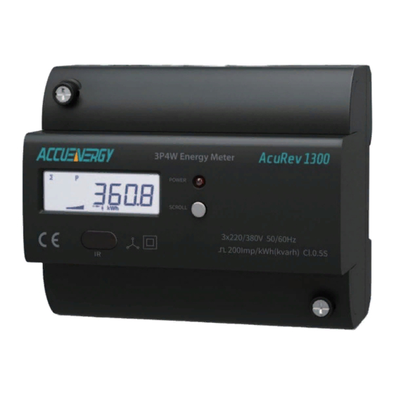
1.1 Meter Overview AcuRev 1300 series rail-mounted three phase energy Meters has a small size and high accuracy, it is ideal for use in distributor and tight spaces. The meter is equipped with an easy to read liquid crystal display (LCD) which displays all the important information. It is ideal for building energy management systems, energy monitoring and energy metering systems. -
Page 11: Areas Of Application
Energy saving system 1.3 Product Features Multifunction, high accuracy AcuRev 1300 series meter has data collection and management function, energy measurement and multi-parameters measurement function, and demand measurement, event logging. The measurement accuracy of energy, power, voltage, current is 0.5. - Page 12 AcuRev1300 series instrument.Almost all of the three-phase system application, and can be used for single phase system. Connection error automatic judgment AcuRev 1300 series instrument connection errors of judgment and help in the process of the project construction cost increase caused by the wrong wiring.
-
Page 13: Chapter 2 Installation
Chapter 2 Installation 2.1 Appearance and Dimensions 2.2 Installation Methods 2.3 Wiring... - Page 14 Before Installtion The installation must be perfomred by qualified, competent accredited professionals who have received formal training and have experience with high voltage and current devices. Appropriate safety wear (gloves, glasses, arc flush suit, etc.) is mandatory to ensure safe installation. ...
-
Page 15: Appearance And Dimensions
This chapter mainly described how to install an AcuRev 1300 series meter, which is a very important step of using the meter correctly. This chapter gives some pictures about how to install the meter and some notes. Before installing the meter, please read this fi rst. -
Page 16: Installation Methods
AcuRev 1300 operating temperature is -25~70°C. Exceeding this temperature range will cause damage to the meter. Please note that it can influence the meter life negatively if themeter operates in extremely high or extremely low temperatures. AcuRev 1300 storage temperature range is -40~85°C. - Page 17 2. Humidity 5% to 95% non-condensing. 3. Location AcuRev1300 series meter should be installed in a dry and dust free environment. Avoidexposing meter to excessive heat, radiation and high electrical noise sources. Installation Steps: This product is DIN railed mounted and fits on the standard 35mm rail. 1.
- Page 18 Figure 2-4 Step B 3. Before mentioning this step, the steps needed to remove the seal/cover need to be mentioned. I.E. Step 5 below should come first.To attach seal/cover back onto the meter place the left side of the cover down onto meter and press down on the right side. When installed correctly you will hear a clicking sound.The steps to attach the other cover is opposite to the above step.
- Page 19 4. After inserting the cover, tighten the sealing screws and lay the seal and tighten the sealing screws, lay the seal. Figure 2-6 Step D 5. To open the cover, remove the seal if applicable, unscrew the sealing screws and life the cover upwards to remove.
-
Page 20: Wiring
2.3 Wiring Terminals: This manual use L1 L2 L3 to represent three-phase current loop, which are the same as A, B, C in other manuals. Figure 2-8 The transformer AcuRev1300 terminal access type distribution A, B, S: communications terminal; P1, P2: pulse output; L, N: auxiliary power;... - Page 21 AcuRec1300 Choice of wire of power supply is AWG22-16 or 0.6-1.5mm2. A fuse (typical 1A/250Vac) or small air circuit breaker should be used in the auxillary power supply loop. Such as the use of small air circuit breaker, it is recommended to use IEC947 standards and through the CE certification of products.
- Page 22 Note: In no circumstance should the secondary of the PT be shorted. The secondary of the PT should be grounded at one end. Please refer to the wiring diagram section for further details. Current Input: Current Transformers (CTs) are required in most engineering applications. Typical current rating for the secondary side of the CT shall be 5A (standard) or 1A (Optional), please refer to the ordering information appendix for further details.
- Page 23 AcuRev1300 series instrument connection mode Settings and the corresponding practical application in engineering and correct, to ensure the measurement accuracy of instrument. 1). 3LN, 3CT; The connection mode set to 3LN LINE A B C N 1A FUSE Terminal Block V3 V2 V1 AcuRev 1300 LOAD...
- Page 24 2). 2LL,3CT (using 2CT); The connection mode is set to 2LL; Note: output transformer secondary side is 5A/1A LINE A B C 1A FUSE Terminal Block V3 V2 V1 AcuRev 1300 LOAD...
- Page 25 3). 2LL,2CT;The connection mode is set to 2LL; Note: mutual inductance type secondary side output for 5A/1A,Rogowski coil 333mV,200mA LINE A B C 1A FUSE Terminal Block V3 V2 V1 AcuRev 1300 LOAD...
- Page 26 4). 1LL , 2CT; the connection mode is set to 1LL. LINE A N B 1A FUSE Terminal Block V3 V2 V1 AcuRev 1300 LOAD...
- Page 27 5) 1LN, 1CT; connection mode is set to 1LN LINE 1A FUSE Terminal Block V3 V2 V1 AcuRev 1300 LOAD...
- Page 28 Relay output wiring diagram 220Vac Auxiliary Power Supply Relay Output...
- Page 29 AcuRev1300 communication utilizes RS485 port, via Modbus-RTU protocol. The wiringterminals are A, B, S. "A" is called differential signal " ", "B" is called differentialsignal"-", "S" is connected to the shielding of shielded twisted pair cable. The maximumdistance of Shielded Twisted Pair cable is 1200 m. The distance will be shorter if moredevices are on the same communication link or using a higher baud rate.
-
Page 31: Chapter 3 Operation And Application
Chapter 3 Operation and Application 3.1 Display Panel and Keys 3.2 Display Mode and Key Operations 3.3 Parameter Display and Key Operations 3.4 Settings and Operations... -
Page 32: Display Panel And Keys
In this chapter, you would see some details about human-computer interaction, including how to use the key to browse demanded information, and how to set the parameters correctly. 3.1 Display Panel and Keys Chapter 2.1 shows the dimensions of Display Module. It consists of one LCD screen and one key. -
Page 33: Display Mode And Key Operations
Four-quadrant reactive power To indicate the first to forth quadrant reactive power display Import icon on: display the Energy Import Export icon on: display the Energy Export Inductance icon on: inductive load Load character indicate Capacitor icon on: capacitive load unit Unit of the parameter in parameter display area 3.2 Display Mode and Key Operations... - Page 34 flag, the consequence would be added to the important parameter display area to cycle display. The corresponding flag would be cleared and expelled from important parameters. System default display data content cannot be deleted.Configuration 2: add or delete the corresponding number through pressing keys. AcuRev1300 instrument power value is positive.The number of significant digits when electricity data (including the number of decimal places) less than 7, normal display;...
- Page 35 All of the meter supported parameters display are in the table below: Table 3-2 Display coding table Setting flag Content Model Model Model Model Page Voltage wiring detection √ √ √ √ Current connection √ √ √ √ detection Instrument address √...
- Page 36 optional display flag word2 Meter run time √ √ √ √ - Bit3 optional display flag word2 Load running time √ √ √ √ - Bit4 3. Setting mode Short press the “set” key, we’ll go into the setting mode: password authentication. When it is succeed then go to the address setting page, or drop out of the setting mode and go to the important parameter setting mode;...
- Page 37 Display interface S-12 S-16 S-16 S-16 S-16 customization:increases Display interface S-13 S-17 S-17 S-17 S-17 customization: cut Incorrect connection S-14 S-18 S-18 S-18 S-18 detection enable Each mode display area distinction as follows: Important parameter mode: The first in the first row do not display s, at the same time, the mode setting position do not display in the last row.
-
Page 38: Parameter Display And Key Operations
B) Short time press (Sc) (the press time is shorter than 2 second) Display mode (including important parameter display mode and all parameter display mode): change pages. Setting mode: change pages and data. C) Long time press (LSc) (the press time is longer than 2 second) Display mode: change mode between important parameter display mode and all parameter display mode. -
Page 39: Settings And Operations
different parameters. The change sequence is from the 1-29 screen(If the chosen specification doesn't support the function , just skip it). When it comes to the last screen, press the same key another time, back to the 1 screen. 3.4 Settings and Operations Under the setting mode, the meter could complete most of the data setting. - Page 40 important parameter display mode. B) Data setting Operation description: No cursor flashing: press the “Sc” key to change pages. Cursor flashing: press the “Sc” key to change the number in the flashing position. “Set” key could change the cursor flashing state, cursor’s movement, confirm to the setting data.
-
Page 43: Chapter 4 Functions And Software
Chapter 4 Functions and Software 4.1 Parameter settings 4.2 Basic Measurement Functions 4.3 Measurement function 4.4 Demand 4.5 RO function 4.6 Event Logging 4.7 Alarm function 4.8 Incorrect connection detection 4.9 Instrument information 4.10 Seal function... -
Page 44: Parameter Settings
Take AcuRev 1304 for example. 4.1 Parameter settings AcuRev 1300 series meters need basic settings so that the meters can work in the scheduled way. The figure below is the display of basic parameters that set by PC tools software. - Page 45 1) Reactive power calculate pattern Real reactive: − − Generally reactive: − 2) Energy pulse output Used to choose the pulse type that represented by the pulse outputted through P1,P2 terminals. Active: P1,P2 terminals output pulse is active power pulse. Reactive: the output pulse is reactive power pulse.
- Page 46 of the thermal demand table. Set 1-30min as a calculate cycle. In the whole cycle, we just need to calculate the demand once. Which means the demand update time is equal to the demand calculate cycle. In this method, in the operation state demand calculation method is displayed to block.
- Page 47 7)Primary side/secondary side to choose Electricity and electric parameter data for one side or the secondary side of data 8) Connection mode According to the actual to select the correct connection mode, otherwise it will lead to the measurement data is not correct. 9) CT PT set According to the practical use of set, otherwise, can lead to inaccurate measurement.
-
Page 48: Basic Measurement Functions
4.2 Basic Measurement Functions AcuRev 1300 mainly measure the Voltage, Current, Power, Frequency, Power Factor, demand. Demand supports power demand,current demand and demand prediction function.Among them, the center line current support calculated value and measured value of two kinds of algorithms, AcuRev1303 and below model using calculated value;... - Page 49 include:Consumed Active Energy,Generated Active Energy,Total Active Energy,Net Active Energy,Consumed Apparent Energy ,Generated Apparent Energy,Four-quadrant Reactive Energy,Consumed Reactive Energy,Generated Reactive Energy,Total Reactive Energy,Net Reactive Energy.
- Page 50 Figure 4-3 Calculation and Measurement Parameter Display System power support time-sharing electricity function, split-phase power does not support this feature According to the demand of users, we can depart the time to several sequence time segments. Each segment can point to the same or different rate (at most 4 kinds of rates ). The meter decides to which rate the current time should belong to according to its inner clock or communication command.
- Page 51 TOU calculation can choose inner clock or communication command mode, which could make the application more flexible. Figure 4-4 TOU Energy Setting Display...
- Page 52 a) The currentrate ofvaluefrom theinternalclock TOU energy time segment setting: at most 14 time blocks.Each block corresponds one segment table (at most 8 time segment tables). Each segment can point to anyone of the 4 rates. User can use different time block, different time segment to fulfil personality demand. But to make sure the time is valid, the meter would examine the time setting strictly.
- Page 53 segment table. The rate parameter is one of 0,1,2,3(0:sharp; 1:peak; 2:valley; 3:even). 6. Holiday setting: the number of holiday is integer from 0-30, after finishing the setting, it would be holiday setting, which format is xx month-xx date. Note: User can customarize the factory settings of time zone segment. When no asking, the meter would be set as the default factory settings.
- Page 54 adjust time(unit: min), according to the above setting format, it would change the DST automatically. Through this function, we can achieve the meter’s DST change automatically. When the clock operates to the DST start setting time, the meter could adjust the clock to some certain time segment in advance.
-
Page 55: Demand
4.4 Demand Demand have four calculation methods: slipping block method, fixed block method, rolling block method, thermal demand method. Users can clear the demand.Support demand prediction, in each minute a demand forecast.Specific set set is introduced in the chapter 4.1. Figure 4-6 Demand Parameter Display... -
Page 56: Ro Function
4.5 RO function AcuRev1300 have relay output (RO), all the way to realize the remote control or alarm output. 4.6 Event Logging The meter supports the event logging of important operation. Including programmingevent, open meter cover event, demand clearevent, event clearance event, meter clearance event. - Page 57 Demand clearance event: clear the demand record, support 3 groups of demand clearance event. Event clearance event: clear the event record, support clear demand clearance event, open meter cover event, programming event, support 3 groups of open meter cover event. Support 3 groups of event clearance event.
-
Page 58: Alarm Functions
4.7 Alarm function AcuRev1300 series instrument event alarm function, which is of the definition of when a parameter changes make events inequality (or) equation was established, and the duration exceeds the preset time limit, the event alarm will be started at this moment, when the alarm parameters of serial number, number, alarm status and alarm occurs as the event was a record store at all times, there can be a maximum of 20 article such records stored in the event log buffer.And can be set as the limit of the RO as alarm output event alarm... - Page 59 1.Single event alarm Settings Table 4 -1 lists the content and address, and the parameters of the first set of set records recorded a total of 12 groups of such Settings, the format is the same. The Modbus Parametric Data type Read and write Numerical range Register...
- Page 60 Delay time: how long will the alarm conditions keep after that event is established.The setting range of 0 ~ 30000, the per unit time is 1 ms, set to zero without delay, immediately trigger the alarm events.1/10 of the communication value of the actual value. Output to the relay: set to 0, alarm occurs, the group is not output from RO.If set to 1, assuming the M11 module is connected, and M11 RO work mode setting of alarm mode in the module, alarm occurs, the group output to the RO1, namely RO1 closed, until all the...
- Page 61 3. Alarm record Available for event alarm record store data buffer can store 20 groups of alarm events, not guarantee a set a record, but with the method of circulation records, the events of the new record will cover the earliest records.When the limit of alarm parameter back to normal, normal value and events also referred to as the event log, user access to the limit of time and return to normal time, you can get the limit the duration of the event.
-
Page 62: Incorrect Connection Detection
4.8 Incorrect connection detection AcuRev1300 series instrument has the function of connection detection, Can be set in the interface to the function that can, in the case of function can make can automatically detect instrument according to the instrument connection mode of connection is correct,its principle is as follows: 1. - Page 63 Bit15 Bit14 Bit13 Bit12 Bit11 Bit10 Bit9 Bit8 Reserve Phase Phase Phase Reserve Phase Phase Phase Voltage A Voltage B Voltage C Voltage Voltage Voltage Missing Missing Missing A wrong B wrong C wrong Connecting Connecting Connecting Bit7 Bit6 Bit5 Bit4 Bit3 Bit2...
-
Page 64: Sealing Function
4.9 Meter Information Available meter type, hardware version, software version, release date, serial number and other basic informationas well as real-time clock ,load, connection test results and seal condition, etc through the meter’s information interface Figure 4-10 Meter Information Display 4.10 Sealing function AcuRev1300 series meters support sealing function. - Page 65 From 101H, we can see if the sealing state is valid. When the sealing key is invalid, the address displays open sealing state. When the sealing is valid, the address displays closed sealing state, and the corresponding content would be shield. Bit0: TOU setting sealing or not Other bits are reserved 209H...
- Page 66 224H The pulse constant √ √ 225H The pulse width √ √ 226H Electricity show decimal digits √ √ Energy : Modbus address (HEX) Parameter description Communication 900H-901H Total Active Energy √ 902H-903H Total Active Energy tariff 1 √ 904H-905H Total Active Energy tariff 2 √...
- Page 67 934H-935H Net Reactive Energy tariff 1 √ 936H-937H Net Reactive Energy tariff 2 √ 938H-939H Net Reactive Energy tariff 3 √ 93AH-93BH Net Reactive Energy tariff 4 √ 93CH-93DH Import Reactive Energy √ 93EH-93FH Import Reactive Energy tariff 1 √ 940H-941H Import Reactive Energy tariff 2 √...
- Page 68 Address Parametric description Communication TOU related parameters 402H-40EH Time-division energy setting parameter 1 √ 420H-5F3H Time-division energy setting parameter 2 √ Daylight Saving Time related parameters 350H-367H Daylight Saving Time related parameters √...
-
Page 69: Chapter 5 Communication
Chapter 5 Communication 5.1 Modbus Protocol Introduction 5.2 Communication Format 5.3 Application Details... -
Page 70: Modbus Protocol Introduction
The chapter’s contents include MODBUS protocol, communication format, application details of AcuRev 1300 series meter. 5.1 Modbus Protocol Introduction 1. Transmission mode The mode of transmission defines the data structure within a frame and the rules used to transmit data. - Page 71 2.1 Frame Format Address Function Data Check 8-Bits 8-Bits N x 8-Bits 16-Bits Table 5-1 Data Frame Format 2.2 Address Field The address field is at the start of the frame. It is composed of 1 byte (8 bits), its decimalvalue range is 0-247.
- Page 72 data that terminals respond to the request. This data may be a numerical value, address or setting. For example, Function Code tells the terminal to read one register, Data Field needs to specify reading from which register and how many registers to read. 2.5 Error Check Field The field allows the error check by master and slave devices.
-
Page 73: Communication Format
intothe most signifcant bit (MSB) position. The LSB is extracted and examined, if the LSB equals to 1, the register is exclusive ORed with a preset, fixed value; if the LSB equals to 0, noaction will be taken. This process is repeated until eight shifts have been performed. Afterthe last (eighth) shift, the next 8-bit byte is exclusive ORed with the register’s current value, and the process repeats for eight more shifts as described above. - Page 74 17th slave device. The data type of energy is dward. Each parameter takes 2 bits, and each bit takes 2 bytes. AcuRev 1300 series meters’ total active energy address are 900H, 901H. Total Active Energy tariff 1 address is 902H, 903H.
- Page 75 2. Preset/Reset Multi-Register (Function Code 10H) Set: Function code 10H allows users to change multiple registers’ content, including system parameter, time-division energy parameter, initialization energy. Table 5-6 is an example of It's Total Active Energy is 0.20KWh,Total Active Energy tariff 1 is 0.12KWh,Total Active Energy tariff 2 is 0.08KWh 17th slave device.
- Page 76 The response data frames: Response data frames, respond to the host data from the machine frame. Include address, function code, the amount of data from the machine and CRC error checking, and packet in each relay occupy a (1 = ON, 0 = OFF), the first byte of the lowest for addressing to relay value, the rest in the back.As shown in table 5-5 for instance relay output state response.
- Page 77 Table 5-9 Independent Control Relay Query DO addr DO addr Value Value CRC16 CRC16 Addr The response data frames: Is a normal response to this command request after the relay state changes back to receive data. Table 5-10 Independent Relay Control Response Response DO addr DO addr Value...
-
Page 78: Application Details
5.3 Application Details 1. Data Type "Bit"is binary value; "Word" is 16-bit unsigned integer, using one register address, 2 bytes. The data range is0-65535. "int16"is 16-bit signed integer, using one register address, 2 bytes. The data range is -32768-32767. "dword"is 32-bit unsigned integer, using two register addresses, high bytes followed by low bytes, using 4 bytes in total. - Page 79 Parameter Relationship Unit System Parameter, Status, The communication value equals No Unit Parameter the real value Real-time Clock, Timestamp The communication value equals No Unit the real value Electrical measurement Used with the scaling factor f of Electrical measurement parameters the measurement parameters parameters' unit PT1, PT2...
- Page 80 System parameter district System parameter decides the device’s working mode. 10H- read command 03H- write command Table 5-13 System Parameters address table MODBUS Parameter Data Access Default Register address Range Model description type Property value number HEX Decimal 200H Meter Address word 1-247 1200;...
- Page 81 Bit0:TOUSet is Sealed or Not Bit1-Bit5: 0 1: valid of Sealed Parameters 209H word corresponding Selection Selection; 0: invalid of corresponding selection 0x02: Meter Reset, Event Reset, write Energy Data 0x04: write Communication Data(except Energy 20AH Revise Operation word Data), Demand Peak Authority reset Note: Register...
- Page 82 Bit0: Reset Demand Record; Bit1: Reset Event Record; Bit2: Reset System Event Record; Bit3: Reset Meter Opening Record; Bit4: Reset Demand Event; Bit5: Reset Alarm Event; Bit6: Reset Meter Operation Time; 20DH Meter Data Reset word Bit 7: Reset Time of Meter Operation with Load Bit8: Reset Meter...
- Page 83 According 212H CT2 Value word 1; 5; 100; 200; 333 to the order 213H CT1 Value word 1~50000/5~50000 214H CTN Value word 1~50000/5~50000 50.0~400.0 (Communication value 215H PT2 Value word 220.0 is 10 times of the real value) 50.0~999999.9 216H- 534- (Communication value PT1 Value...
- Page 84 RS485 communication way √ √ √ of checking Hardware version √ √ √ √ Software version √ √ √ √ The release date √ √ √ √ specifications √ √ √ √ The input active power √ √ √ √ optional display flag The input active power (A - 11-13...
- Page 85 301H clock: month word 1-12 302H clock: date word 1-31 303H clock: hour word 0-23 304H clock: minute word 0-59 305H clock: second word 0-59 306H Week word 0: Sunday 1~6 Monday- Saturday 310H- 784-785 Run_tim Uint32 0-999999999 311H (Communication value is 100 times o0f the real value) 312H-...
- Page 86 355H DST Start Min Word 0-59 356H DST Start Adjust time Word 1-120 (Unit: Minute) 357H DST Ending Month Word 1-12 358H DST Ending Date Word 1-31 359H DST Ending Hour Word 0-23 35AH DST Ending Minute Word 0-59 35BH DST Ending Adjust Word 1-120...
- Page 87 Time of use(TOU) energy Table 5-17 TOU Energy Address Modbus address Data Register Parameter description Data range Default Model type number Decimal TOU Parameter See Appendix “Tariff Wrong Parameter 400H 1024 Parameter Setting 1 Wrong Information 1” See Appendix “Tariff Wrong Parameter 401H 1025...
- Page 88 TOU auto reset fixed 40AH 1034 date: hour (default is Word R/W 0-23 0: disable; 1: 40BH 1035 TOU Enable Word R/W enable 0: System Setting 40CH 1036 TOU Settings Number Word R/W Communication Only can change Current number of when TPU 40DH 1037...
- Page 89 Time Zone 7: starting 432H- 1074- Month, Day, schedule 00-00 00 434H 1076 Table number Time Zone 8: starting 435H- 1077- Month, Day, schedule 00-00 00 437H 1079 Table number Time Zone 9: starting 438H- 1080- Month, Day, schedule 00-00 00 43AH 1082 Table number...
- Page 90 Schedule Table 453H- 1107- 1, 4th segment 00:00 00 455H 1109 (Hour, Minute, Tariff Number) Schedule Table 456H- 1110- 1, 5th segment 00:00 00 458H 1112 (Hour, Minute, Tariff Number) Schedule Table 459H- 1113- 1, 6th segment 00:00 00 45BH 1115 (Hour, Minute, Tariff Number)
- Page 91 Schedule Table 46EH- 1134- 1, 13th segment 00:00 00 470H 1136 (Hour, Minute, Tariff Number) Schedule Table 471H- 1137- 1, 14th segment 00:00 00 473H 1139 (Hour, Minute, Tariff Number) Schedule Table 2, 474H- 1140- 1st -14th segment 00:00:00 49DH 1181 (Hour, Minute, Tariff Number)
- Page 92 The 1st special day( 59AH- 1434- Month, Day, schedule 03-12 01 59CH 1436 Table number) The 2nd special day( 59DH- 1437- Month, Day, schedule 09-10 02 59FH 1439 Table number) The 3rd special day( 5A0H- 1440- Month, Day, schedule 05-02 03 5A2H 1442 Table number)
- Page 93 Rate parameter error information word 1(basic parameter) Table 5-18 Rate parameter error information word 1 Bit7 Bit6 Bit5 Bit4 Bit3 Bit2 Bit1 Bit0 Weekend Holiday set Holiday no. Time zone Time zone Time seg Time seg no. Rate no. seg set error error over set error...
- Page 94 Uint16 0x53756e53 1001H 4097 1002H 4098 Uint16 1003H 4099 Lenth Uint16 Well known 1004H- 4100- value registered Manufacturer string Accuenergy 1~4 1013H 4115 with SunSpec for compliance Manufacturer 1014H- 4116- Model string specific value (32 AcuRev1300 1~4 1023H 4131 chars)
- Page 95 (abc) meter --204 1046H 4166 Lenth Uint16 Amps (total): Sunspec; 1047H 4167 int16 0~9999 A Total Current: Acurev 1300 Amps Phase A: Sunspec; 1048H 4168 int16 0~9999 A Phase A Current: Acurev 1300 Amps Phase B: Sunspec; 1049H 4169...
- Page 96 Amps Phase C: Sunspec; 104AH 4170 int16 0~9999 A Phase C Current: Acurev 1300 Current scale -3~+5 (used as factor: Sunspec; 104BH 4171 sunssf exponent of a CT Ratio: Acurev power of 10) 1300 Voltage LN (average): Sunspec; 104CH 4172...
- Page 97 Phase Voltage BC: Sunspec; 1052H 4178 int16 0~9999 V Line BC Voltage: Acurev 1300 Phase Voltage CA: Sunspec; 1053H 4179 int16 0~9999 V Line CA Voltage: Acurev 1300 Voltage scale 1054H 4180 sunssf -2~2 factor: Sunspec; 1055H 4181 Frequency int16 45Hz—65Hz...
- Page 98 Watts phase C: Sunspec; 105AH 4186 Phase C Active int16 0~9999 W Power: Acurev 1300 Real Power scale 105BH 4187 sunssf 0 ~ 4 factor: Sunspec; AC Apparent Power VA: Sunspec; 105CH 4188 int16 0~9999 VA Total Apparent Power: Acurev 1300 VA phase A: Sunspec;...
- Page 99 Total Real Energy Exported: 106BH- 4203- Sunspec acc32 0-999999999 Wh 106CH 4204 Total Active Energy Exported: Acurev 1300 Total Watt-hours Exported in phase A: Sunspec; 106DH- 4205- Total Active acc32 0-999999999 Wh 106EH 4206 Energy Exported in Phase A: Acurev...
- Page 100 1300 Total Real Energy Imported: 1073H- 4211- Sunspec; acc32 0-999999999 Wh 1074H 4212 Total Active Energy Imported: Acurev 1300 Total Watt-hours Imported phase A: Sunspec; 1075H- 4213- Total Active acc32 0-999999999 Wh 1076H 4214 Energy Imported in Phase A: Acurev...
- Page 101 107AH 4218 Energy Imported in Phase C: Acurev 1300 TotWh_SF: Sunspec; 107B 4219 sunssf -3 ~ 0 CT ratio X PT ratio: Acurev 1300 Total VA-hours Exported: 107CH- 4220- Sunspec; acc32 0-999999999 VAh 107DH 4221 Total Apparent Power Exported: Acurev 1300...
- Page 102 Total VA-hours Imported: 1084H- 4228- Sunspec; acc32 0-999999999 VAh 1085H 4229 Total Apparent Power Imported: Acurev 1300 Total VA-hours Imported phase A: Sunspec; 1086H- 4230- Total Apparent acc32 0-999999999 VAh 1087H 4231 Power Imported in Phase A: Acurev 1300 Total VA-hours Imported phase B: Sunspec;...
- Page 103 Total VAR-hours 1091H- 4241- Imported Q1 acc32 0-999999999 varh 1092H 4242 phase B Total VAR-hours 1093H- 4243- Imported Q1 acc32 0-999999999 varh 1094H 4244 phase C 1095H- 4245- Total VAR-hours acc32 0-999999999 varh 1096H 4246 Imported Q2 Total VAR-hours 1097H- 4247- Imported Q2 acc32...
- Page 104 0-999999999 varh 10ACH 4268 phase C TotVArh_SF: Sunspec; All the energy use 10ADH 4269 sunssf CT ratio X PT ratio: the same SF Acurev 1300 10AEH- 4270- Meter Event Flags bitfield32 10AFH 4271 SunSpec_end_ID: 10B0H 4272 Uint16 0xFFFF Sunspec; SunSpec_end_...
- Page 105 Maximum demand and time of occurrence(03H:read) Table 5-22 Maximum demand and time of occurrence address M o d b u s Data Register Parameter description R/W Data range Default Model address(HEX) type number Currentmaximum demand and time of occurrence data 1600H-1601H Input active power’s total Float...
- Page 106 1632H-1633H Input reactive power’s Float Xx.xxxx kvar 1634H-1636H total max demand and Dword YYMMDDhhmmss occur time 1637H-1638H Input reactive power rate1 Float Xx.xxxx kvar 1639H-163BH max demand and occur Dword YYMMDDhhmmss time 163CH-163DH Input reactive power rate2 Float Xx.xxxx kvar 163EH-1640H max demand and occur Dword...
- Page 107 1673H-1674H C phase current max Float Xx.xxxx kvar 1675H-1677H demand and occur time Dword YYMMDDhhmmss 1678H-1690H reserved Event logging (03H:read) Table 5-23 Event logging Modbus address Parameter Data Register Data range Default Model description type number Decimal Total times of Event Reset 1 D 0 0 H - (Total Reset...
- Page 108 Programming record Table 5-24 Programming record address Modbus address Parameter Data Register Data range Default Model description type number Decimal 1A00H- 6656- total Dword 0-999999 1A01H 6657 programming time last time programming record 1A02H- 6658- occur time word YYMMDDhhmmss 1A04H 6660 1A05H 6661...
- Page 109 1B02H- 6914-6916 occur time word YYMMDDhhmmss 1B04H last 2 time 1B05H- 6917-6922 1B0AH Open cover record Table 5-26 Open cover record address Modbus address Parameter Register Data type R/W Data range Default Model description number Decimal 1C00H- 7168- total open word 0-999999 1C01H...
- Page 110 1 : c l e a r t h e p r o g r a m m i n g records event clearance data 1D05H 7429 word 2: clear demand flag records 3: clear open cover records last 2 time 1D06H- 7430-...
- Page 111 RO control(05H) Table 5-30 RO control function-05H Write Modbus Parameter Register Data type R/W Data range Default Model address(HEX) description number FF00: ON 0000H RO control word 0000: OFF...
-
Page 113: Appendix
Appendix Appendix A Function List Appendix B Technical Data and Specification Appendix C Ordering Information Appendix D Revision History... -
Page 114: Appendix A Function List
Appendix A Function List Function AcuRev 1301 AcuRev 1302 AcuRev 1303 AcuRev 1304 Bi-directional Energy Measurements Active Energy Reactive Energy Apparent Energy Power Demand ... - Page 115 Appendix B Technical Specifications and Parameters The transformer connected to the measurement Parameter Accuracy Resolution Range Active energy 0.5% 0.1kWh 0-999999.9 Reactive energy 0.5% 0.1kvar 0-999999.9 Apparent energy 0.5% 0.1kVAh 0-999999.9 Voltage 0.5% 0.1V 175.0V-265.0V Current 0.5% 0.001A 100mA-80A Active power 0.5% 0.1W -80-80kW...
- Page 116 Relay Outpur Load Voltage 250Vac30Vdc Max Load current 5A(Resistant Load) Isolation voltage 2000Vac(1min) Action Time 10ms Mechanical Life 20million times Electrical Life Above 50,000Times(5A,250Vac, Resistant Load Communication RS485Baud Rate 1200-38400 Communication protocol Modbus-RTU Infrared Communication Non- contact infrared Infrared Baud Rate 1200 Environment Working temperature...
-
Page 117: Appendix C Ordering Information
Appendix C Ordering Information Ordering description AcuRev A3: 5A/1A Current A4: 333mV A5: 200mA/100mA/80mA A6: Rogowski coil AcuRev 1301 Model AcuRev 1302 AcuRev 1303 AcuRev 1304... -
Page 118: Appendix D Revision History
Appendix D Revision History Version Date Description V2.01 20141021 First version V2.02 20150923... - Page 120 Your Power and Automation Partner! Accuenergy Corporation Toronto - Los Angeles - Beijing North American Toll Free: 1-877-721-8908 Email: support@accuenergy.com Web: www.accuenergy.com...
Need help?
Do you have a question about the AcuRev 1300 and is the answer not in the manual?
Questions and answers